Computer-controlled cutting

week 4
February 6, 2019
This week we need to explore different kinds of computer-controlled cutting. I will make a sticker with the vinyl cutter and an assembly with pieces of wood that I cut with the laser cutter.
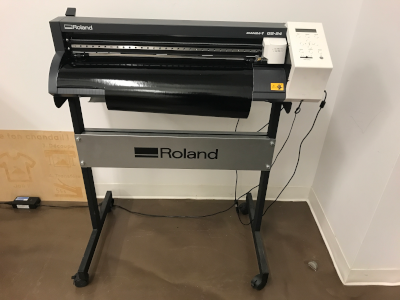
Explore vinyl cutter Roland GS-24
Installation of softwares
To be able to use the Roland vinyl cutter, you need to install some softwares. I found the list directly in the manual in section "Simple! Basic Cutting". You also just click on this link to start your first download.
For windows installation:
1-Install the Roland driver
2-Install Roland OnSupport
3-Install CutStudio
4-Install the Inkscape plug-in for CutStudio
You can find the plug-in right here and you need to put the .py and the .inx file directly in your extension folder.
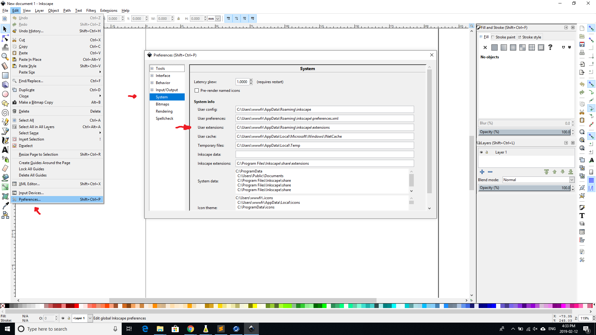
You can find your extension folder like this.
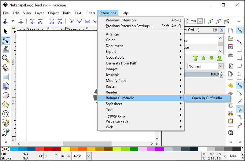
When you want to send your image from InkScape to CutStudio, You need to go on extensions tab and select Roland CutStudio.
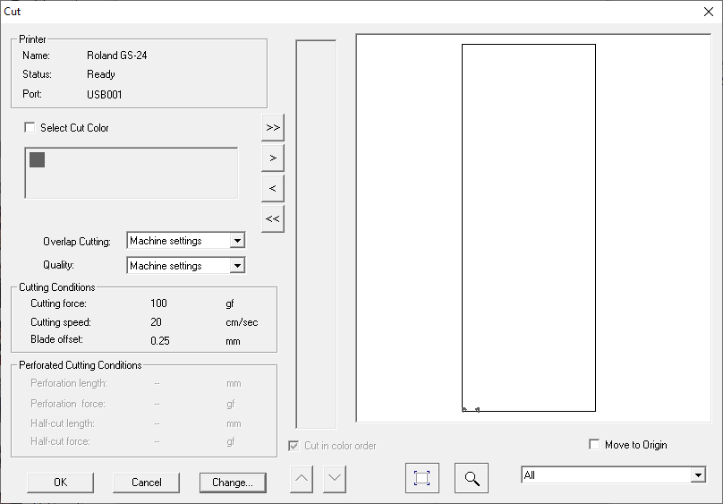
Here are the parameters for the material that I want to cut.
Machine Setup
After you power on the vinyl cutter, you need to insert your vinyl into the machine. It's really important that the little wheels that holds the vinyl are into the white space.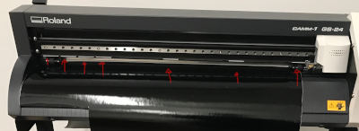
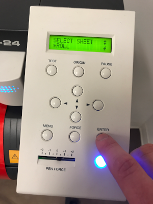
The next step is to choose the type of paper. In this case we select Roll and press enter. After that, we need to place the origin. Position the head where you want your drawings to start with the arrows on the control panel.
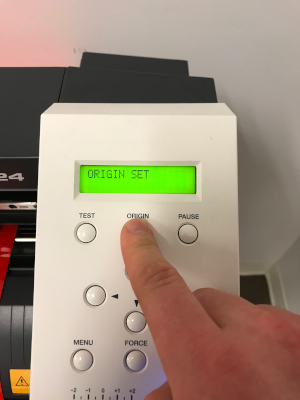
When the origin is chosen, press the button origin for a few seconds to fix the origin.
Project
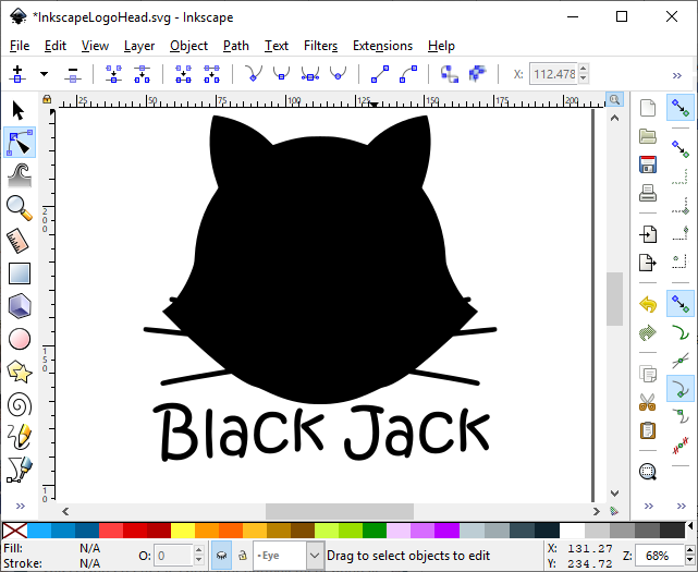
I chose to make my logo that I made last week on vinyl cutting.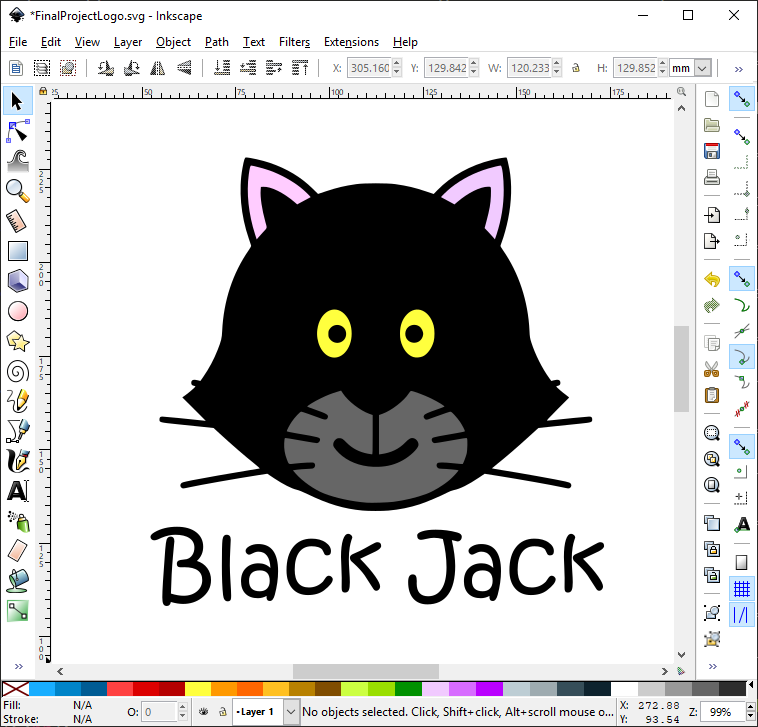
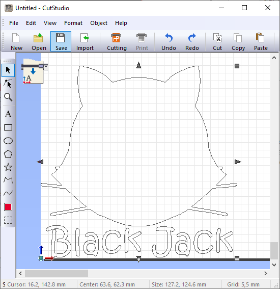
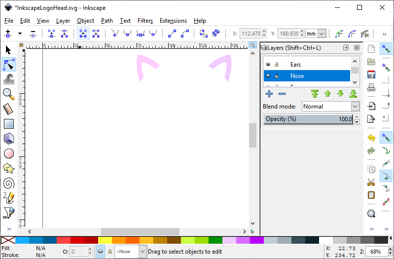
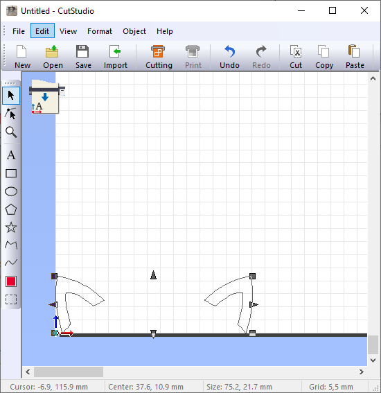
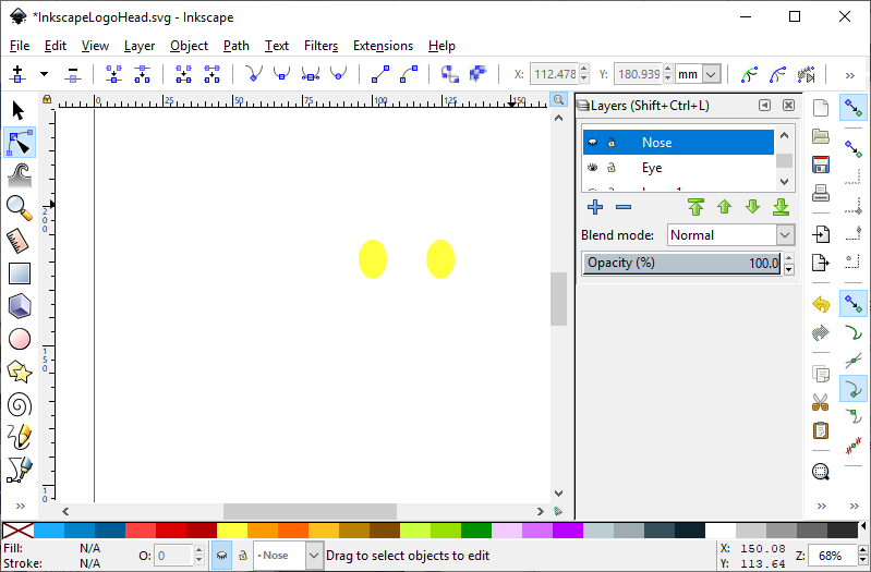
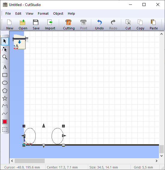
With this type of vinyl cutting, one must cut one color at a time and then assemble them at the end. So in InkScape, I separated each color into a different image and then was able to cut it with the machine.
The head of the cat and letters
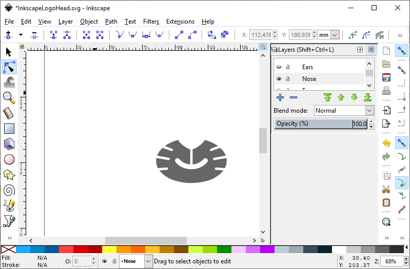
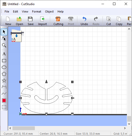
The nose of the cat.
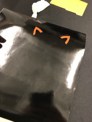
The ears of the cat.
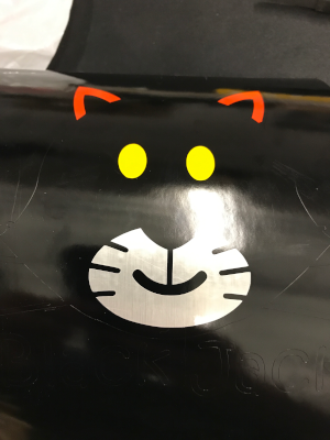
The eyes of the cat.
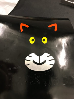
Now is the time to stick all part together.

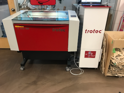
Explore Trotect Speedy 300 laser cutter
Installation of softwares
You have to install the software that comes with laser cutting. Normally it installs with a CD that came with Trotec. You can find the manual right here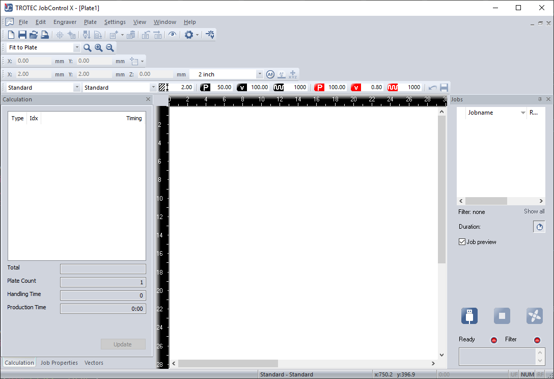
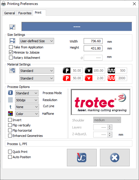
After the installation, you need to set your preferences.
Machine Setup
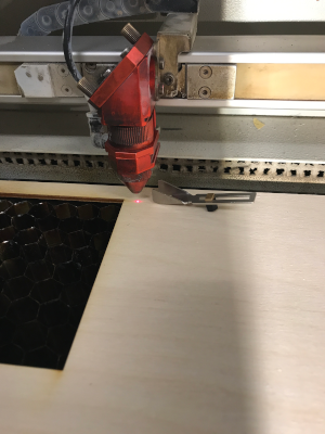
The first step is to power on the laser machine and the air filter. After that, you need to focus the laser. You move the head of the laser with the arrows on the control panel and you position it over the material to be cut.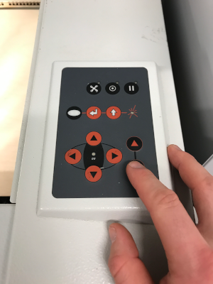
The next step is to put the rule that comes with laser cutting to be able to adjust the height of the laser to have the best focus.
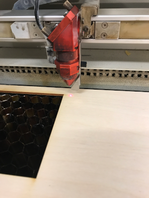
The next step is to move the board very slowly up until the ruler falls.
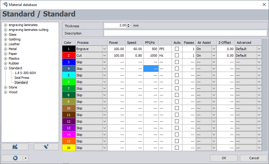
Now it's time to check the setting for the laser cutter in the program JobControl.
Group assignment
The person who documents the group assignment this week is Annie Ferlatte but this week I also did my own little test.For the group project, we had to characterize our laser cutter. So we decided to make a small test board with different parameters.
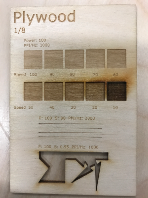
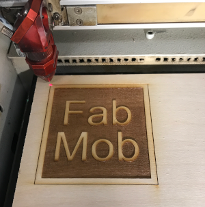
I decided to test the parameters of this test. So I made a small sign to try engraving and cutting at the same time.
Project
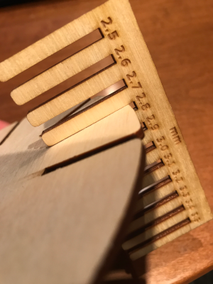
This week we had to do two projects. The first project is a rule to determine the thickness of our material. It is important to be very precise so that our press fit project is well done. Also, both projects are a parametric design so that it is easier to make adjustments.I decided to make the rule of 25 mm up to 35 mm because the material should have a thickness of 30 mm.
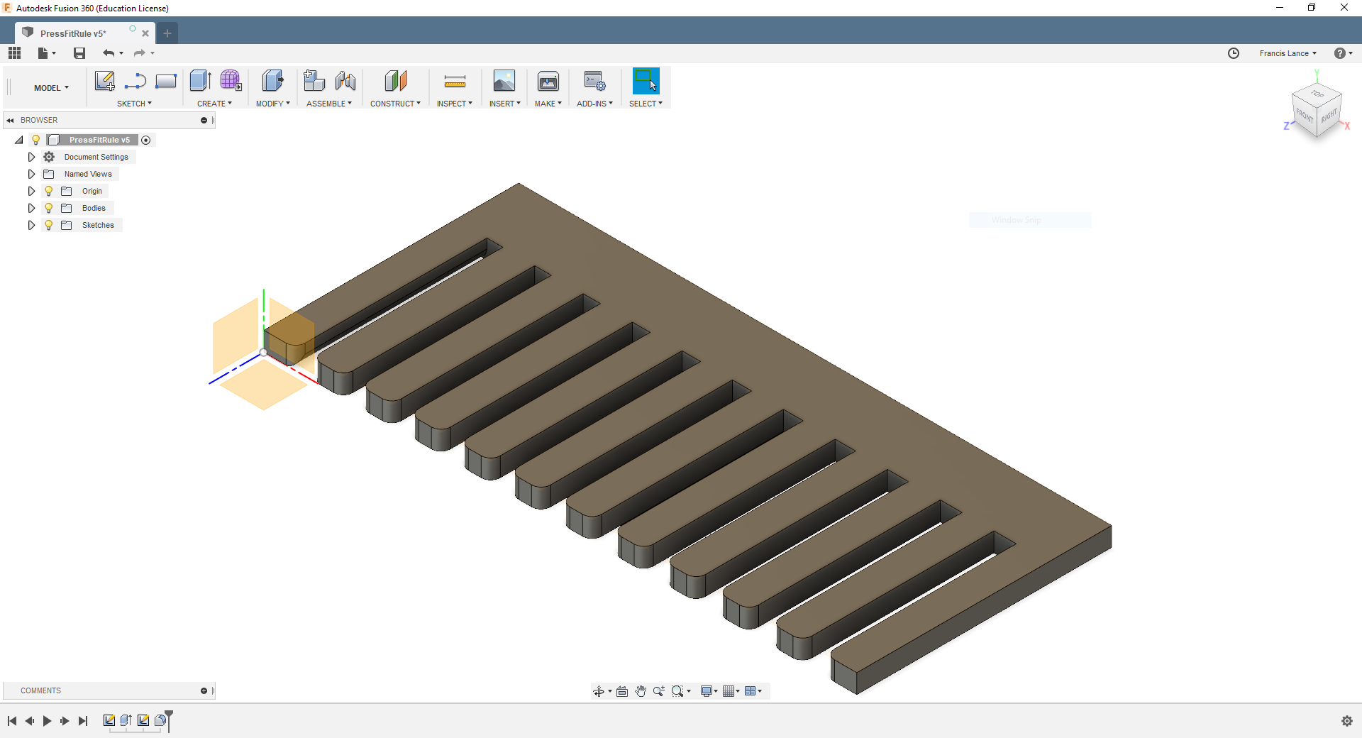
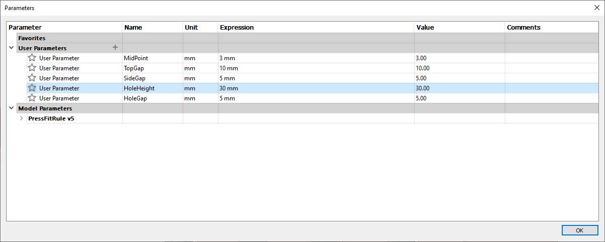
This is my parameters used in my design.
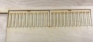
This is my rule after being laser cut.
Here is the final result.
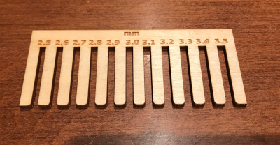
As you can see, the true thickness of the material to be press fit is 2.8 mm.
Press fit project
For my pressfit project, I decided to make five pieces of simple shape with holes to insert them into each other. I decided to do my design in the Fusion 360 software. The idea of doing a project like that came to mind when I saw someone playing with legos. I thought I would make my own pieces to assemble as desired.
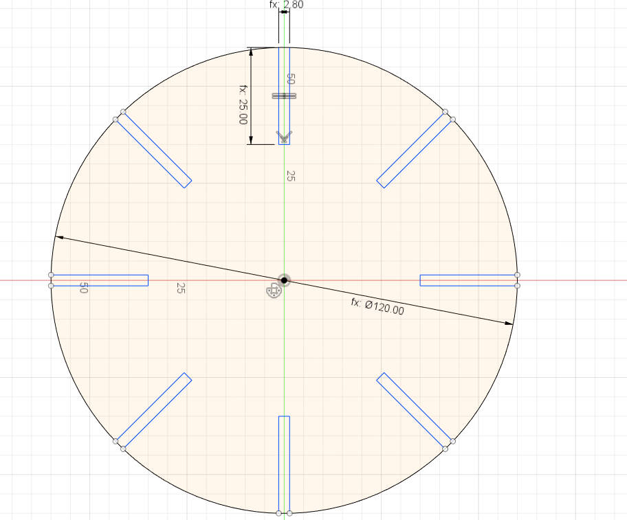
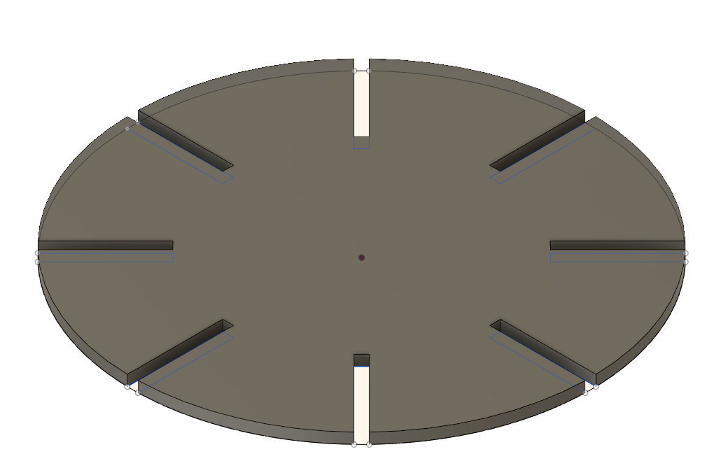
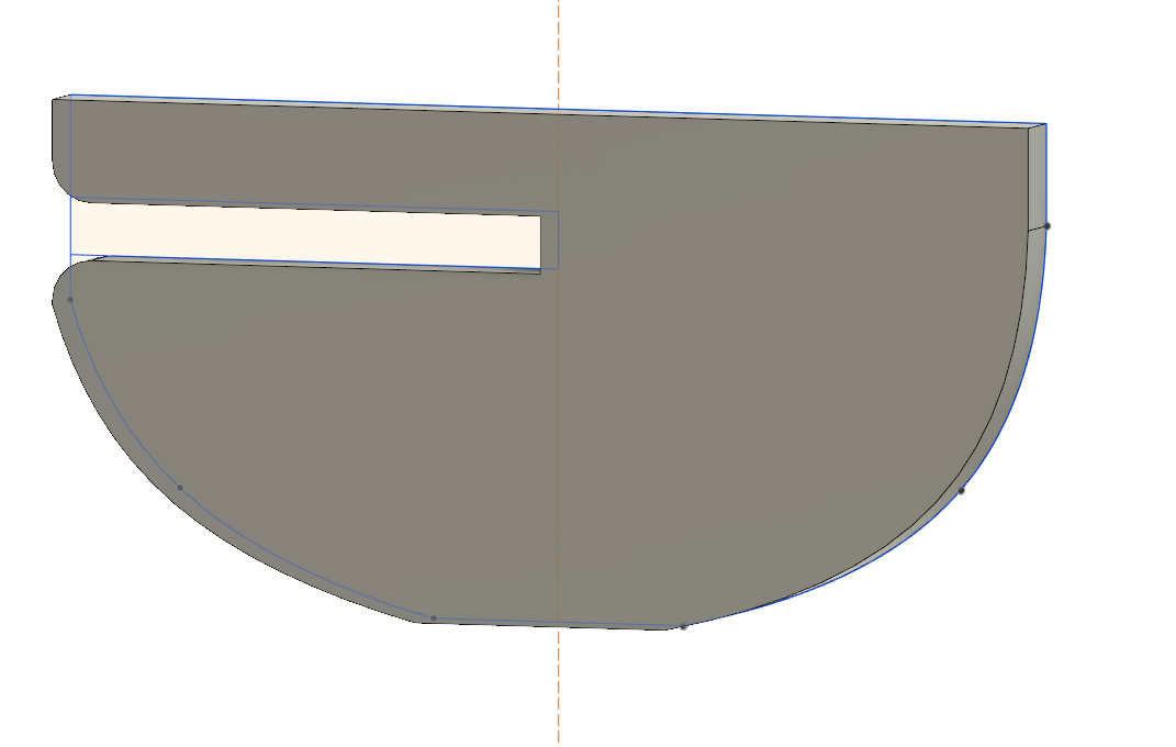
I decided to start by making a piece that would be my base for connecting the other pieces. So I decided to make a pretty big and round pieces. Here is the sketch of my play. I made a circle and a first hole. Later, I used the circle pattern tools to repeat the hole around the circle. The size of the hole is 2.8 mm wide to go with the thickness of the material chosen with our rule made above.
After that, I put the same thickness to the room as the actual thickness of the board we are cutting.
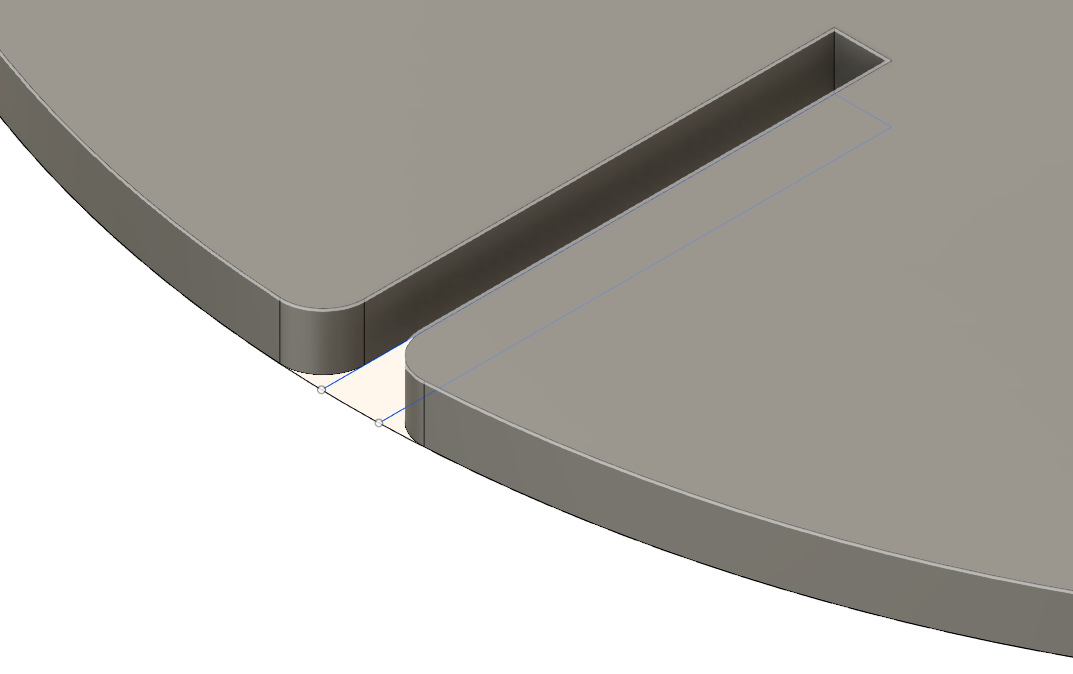
Finally, the most important thing is to put filets on each side of the hole to facilitate insertion between parts.
To be able to deposit my design on a surface, I design a piece serving as foot of my design with the same hole width that is 2.8 mm.
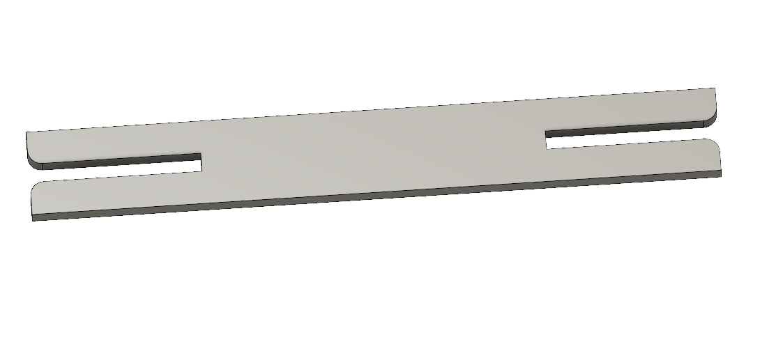
To be able to connect two pieces without having space between the two pieces to connect, I designed a small connector to be able to connect them.
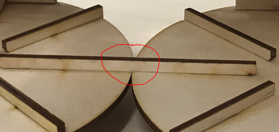
This photo shows that there is no gap between the two parts that have been connected with the small connector.
I now needed a piece that would serve as a wall in my designs. So I decided to design a connector much wider and higher than the first one.

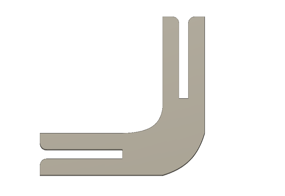
For not having a flat design, I needed a last piece that was to make a 3D assembly. This piece is a connector but with a 90 degree angle.
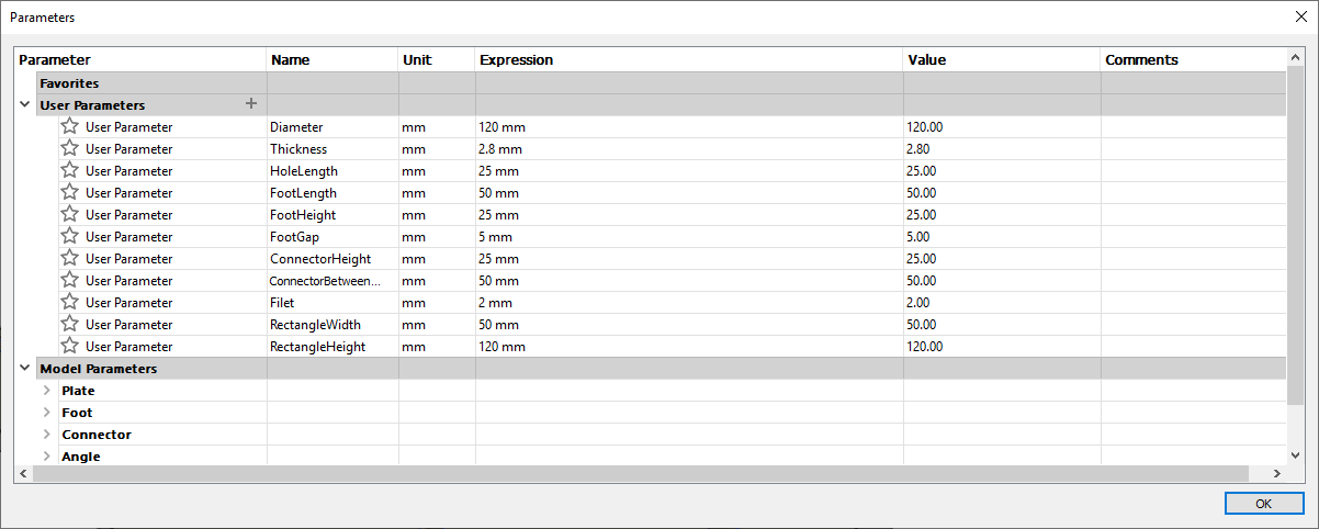
This is my parameters used in my design. The three parameters that I changed after trying to insert my parts are the thickness during my test, the length of the holes (HoeLenght) to improve the insertion of the parts and the length of the small connector (ConnectorBetweenGap) to have no space between the pieces when they are connected.
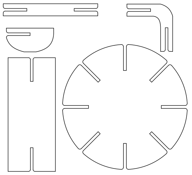
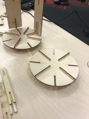
Here are the five pieces drawn in my press fit design.
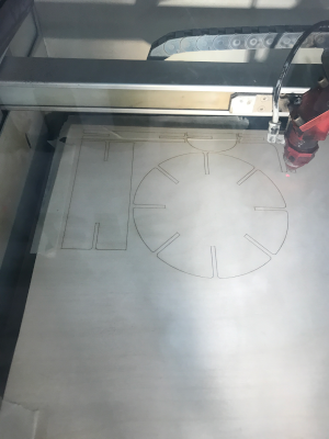
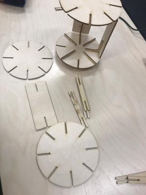
Here are some pictures during laser cutting and during the assembly.
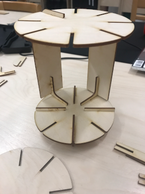
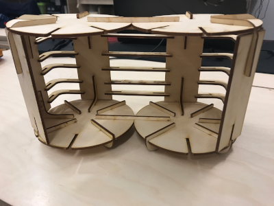
Here is the final result seen from the front. I use it as a thing holder on my desk.
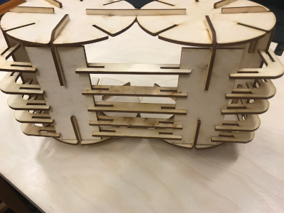
Here is the final result seen from the back.
You can download all the files of this week right here.