
For this week. We need to Design a machine (mechanism + actuation + automation), Build the mechanical parts and automate it. We didn't want to do a project with no purpose, so we decided to look for an opportunity to build something useful. In our company, we have a project for the Ministry of Education to Develop, equip and support the technical and digital workshops for the High schools for males and females in the Kingdom of Saudi Arabia. The aim is to provide standards, competency-based education and performance indicators and educational and training curriculum for the high schools technical and vocational workshops including curriculum tools (printed, digital and interactive)
Saudi Vision is a national vision for the present and future of the Kingdom of Saudi Arabia. It is set to express the aspirations of the Kingdom towards success and excellence, which depends on human resources. Therefore, the Ministry of Education adopted a series of projects to support the National Transformation Program, including “Develop, equip and support the technical and digital workshops for the High School Workshops: First Phase”. The aim of these projects is to promote students basic vocational and technical skills they need in their daily life, to prepare them to the job market and to train them on these skills through delivering technical and vocational programs in workshops in high schools that students can choose from.
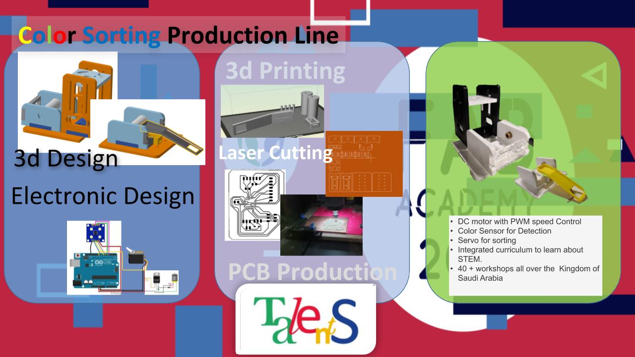
They requested us a hands-on workshop in which students learn from a real-life industrial application, and we decided to create a scale conveyor which is flexible to add on different curriculum, and the student will learn about many different topics.
To develop this idea, we created as a team a brainstorming session in which we draw all the possibilities, and we split the work between the team. To start, we will have to do the following
The first interaction of our work we used Onshape as an online CAD platform to design. We focused on the conveyor design. The two bases on the corners are for the conveyor. And the platform in the center is for the sensors.
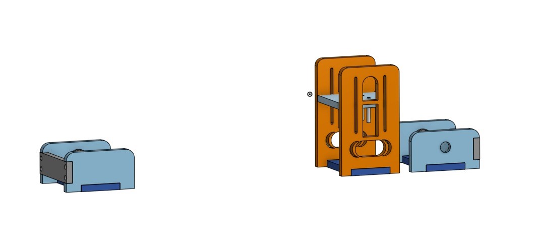
Then, we did a brainstorming sesion for the actuators, and decided we wanted a moving slide at the end for the conveyor to color sort the items.
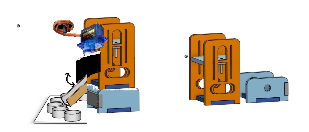
After some interactions, we arrived to a design that looks like this:
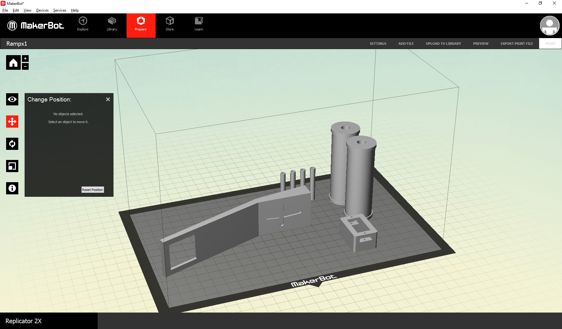
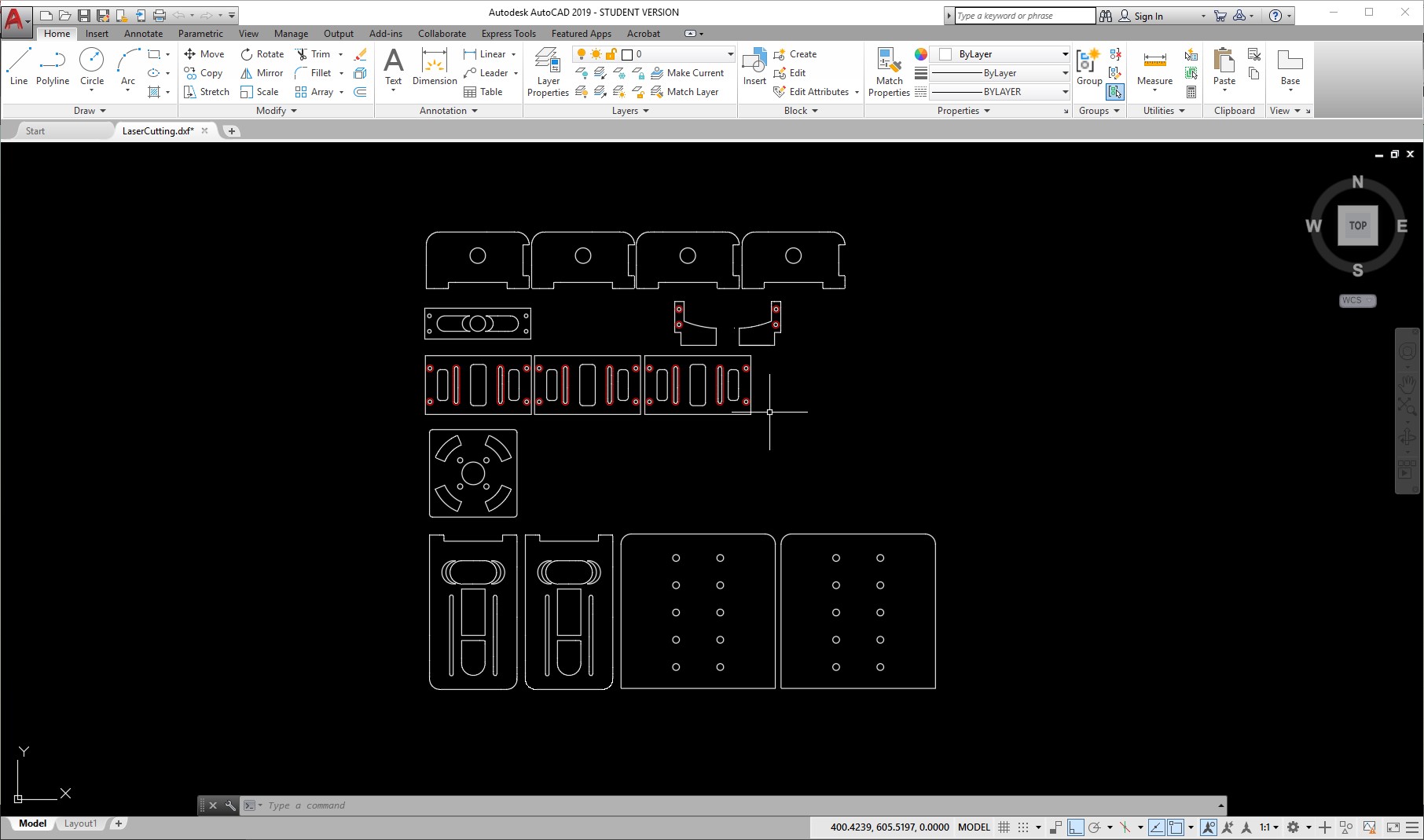
Then, we created planned the manufacturing using laser cutters and 3d printers. For this, we separated the parts and exported stls for the files that need to be 3d printed:
And then created 2d blueprints of the parts that need to be laser cut.
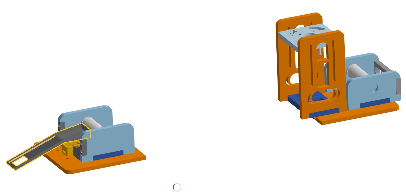
After this, we started the production using the machines in our lab.
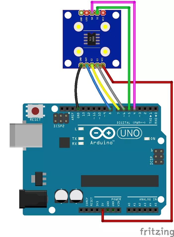
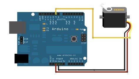
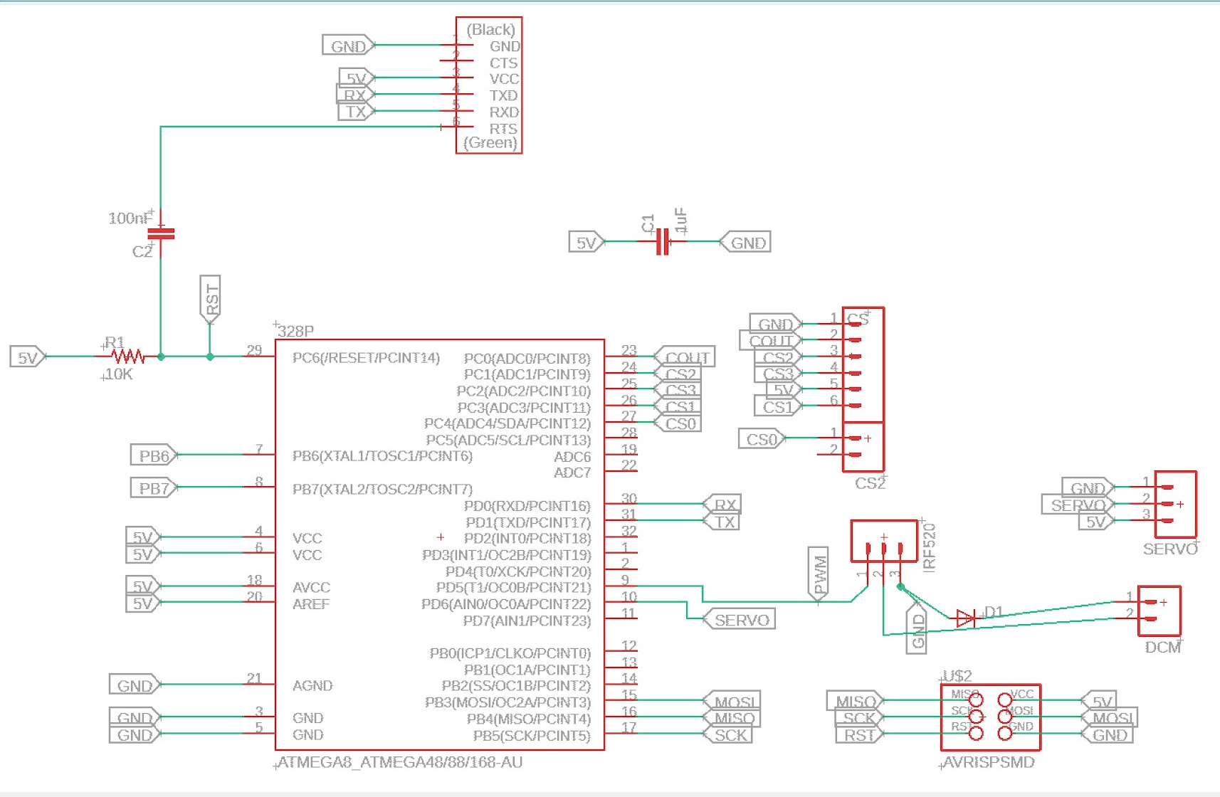
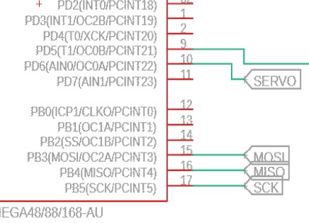
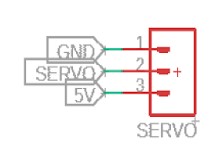
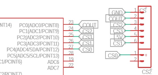
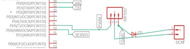
At the same time, we decided to create a PCB with input for the color sensor as input and a servo for sorting and a dc motor for movement as an output. For this, we modified our generic satcha kit board and added the necessary components for this to work.
The circuits needed are the following:
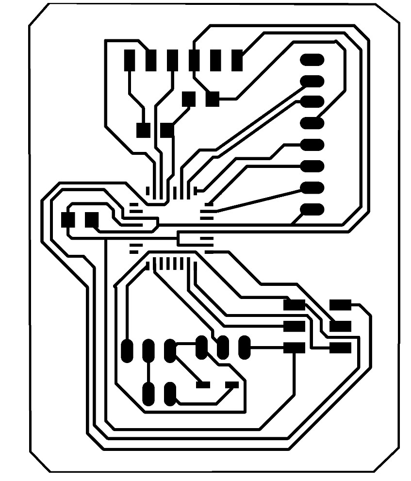
After integrating, optimizing and testing our circuits, we arrived to the following design

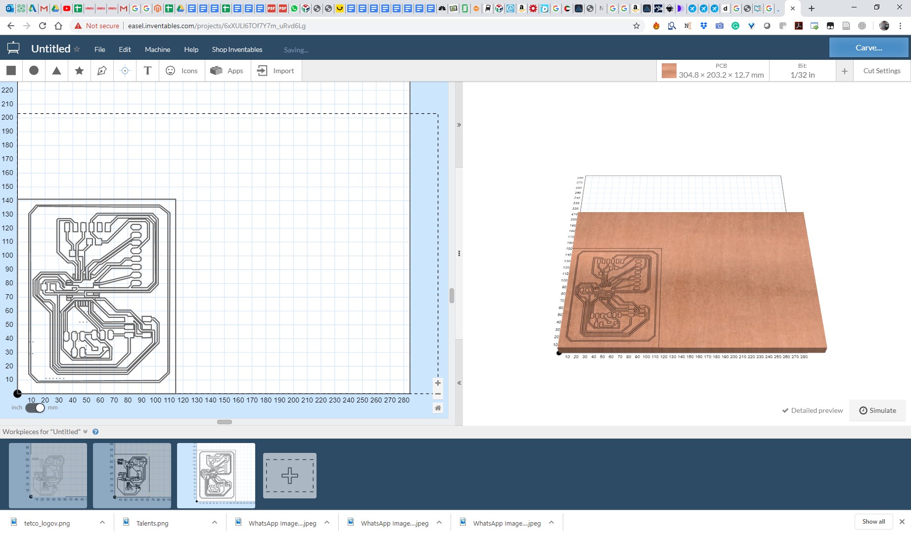
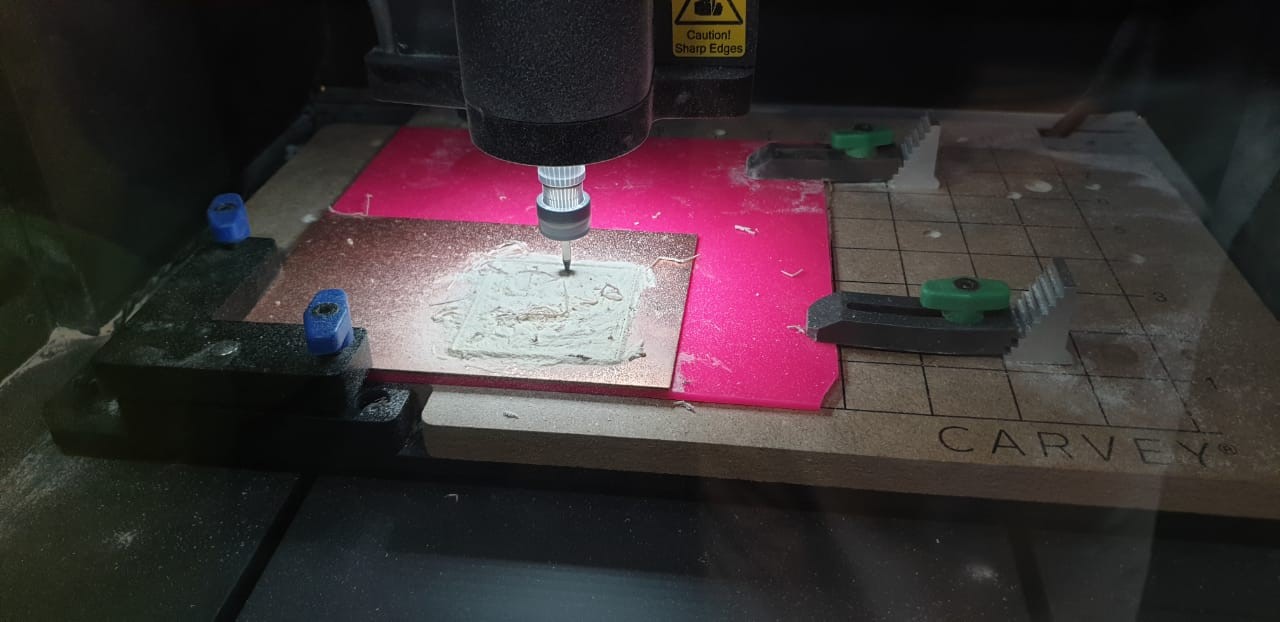
Which now are going to fabricate using a Carvey machine.
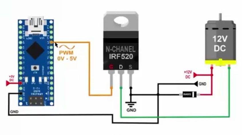
For testing, we tried a simpler design with an Arduino, while we solder the components and finalize the fabrication of our parts.
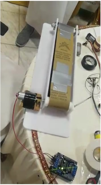
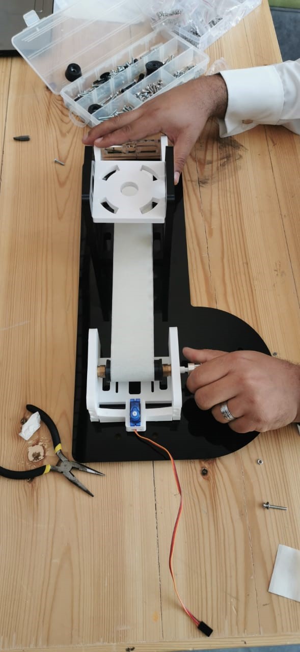
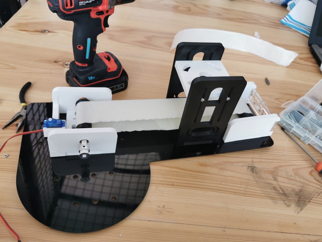
Now, after printing the parts, and my group assembled it, this is how it look:
The Poster for this project
Video
MANUAL MOVING.mp4
Downloads:
Download File: Conveyor.step
Download File: LaserCutting.dxf
Download File: Layout1
Download File: Layout2
For this week. We need to automate the machine we built in mechanical design last week. For this, I will explain the board I design for this, and then show how our group integrates all the parts to have this machine working. As explained last week, the circuits we needed for functionality are a component for dc motor control, the component for the color sensor, and the component for a servo.
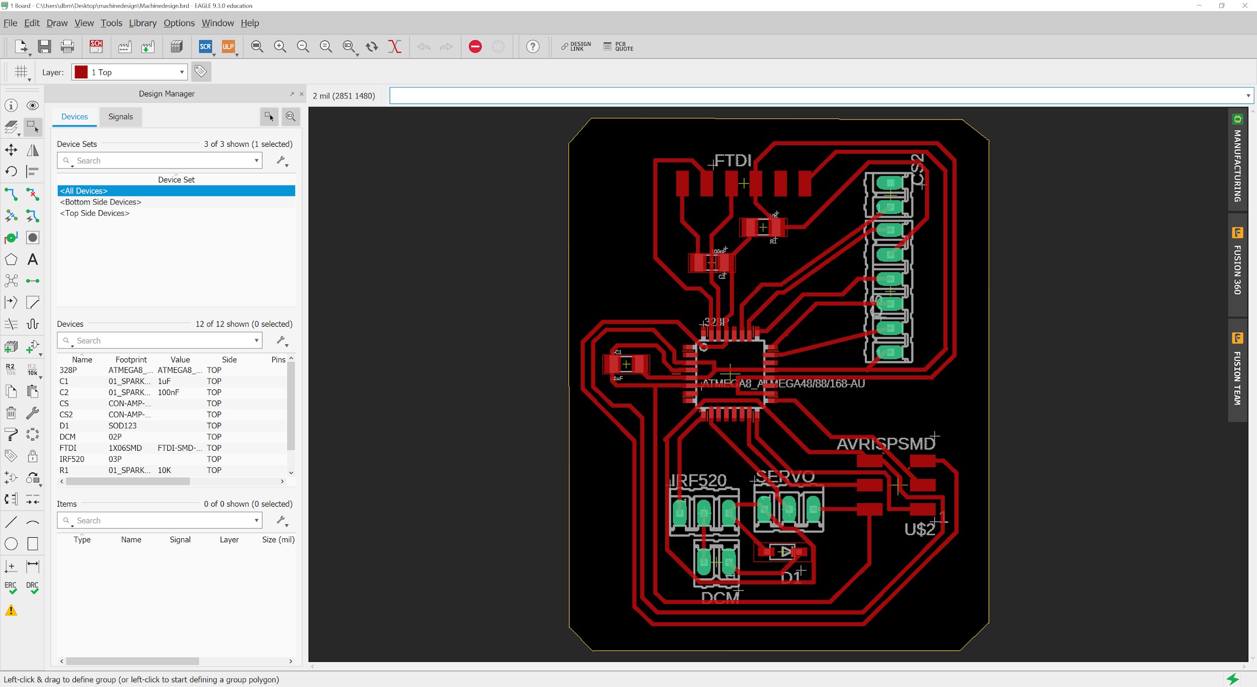
After integrating, optimizing and testing our circuits, we arrived to the following design

Based on the satcha design, I did the following modifications to include the circuits needed:
This is the final layout of the board,

And as explained last week, it was fabricated using a Carvey machine.


Now, we are ready for soldering.
My friends Hussain Alhudhud worked on the soldering and he documented it in his page http://fabacademy.org/2019/labs/dhahran/students/hussain-alhudhud/machine.html
My friend Yousef ALsenwar worked on the programming and he documented on his page http://fabacademy.org/2019/labs/dhahran/students/yousef-alsenwar/week17.html
The final video