-
Assignment
Machine DesignMachine Design
This week assignment, I should actuate and automate the model that we have done in Mechanical Design Week
The conveyor that we built was good and easy to move as I did the movement manually. What we need to do this week is to make the functionality to do what we planned before which is sorting the colors and keeping them in different containers
We are planning to design and build microcontroller board that controls the DC motor (moving the belt) and servo motor (guiding different colors to different containers) based on the color that detected by color sensor
We held the first meeting between us to decide which is the suitable chip and what are the exact parts that we are going to use. The group is the same group for Mechanical design week ( Mass, Hussain, and I)
The microcontroller chip that we’ve decided to use is Atmega328P, because it has enough I/O pins that we can use. And the components that we are planning to use are: DC motor to move the belt, Servo motor to select the right container, and color sensor to detect the color so that the servo select accordingly
So, we started doing the work, each one of us is responsible for set of tasks, however, we will keep holding meetings to check the progress and make sure to integrate the work to get the project done
I will be responsible for designing the shaft and preparing the code for the microcontroller board to get the colors sorted
The parts that were printed during the mechanical design week are ready, so, all I need is to measure the roll that hold the belt, because the shat will be fixed inside it. The shaft should be tight enough to make sure that the belt moves when the motor moves. I used digital caliper to take the measurements and I checked the design file using onshape as well
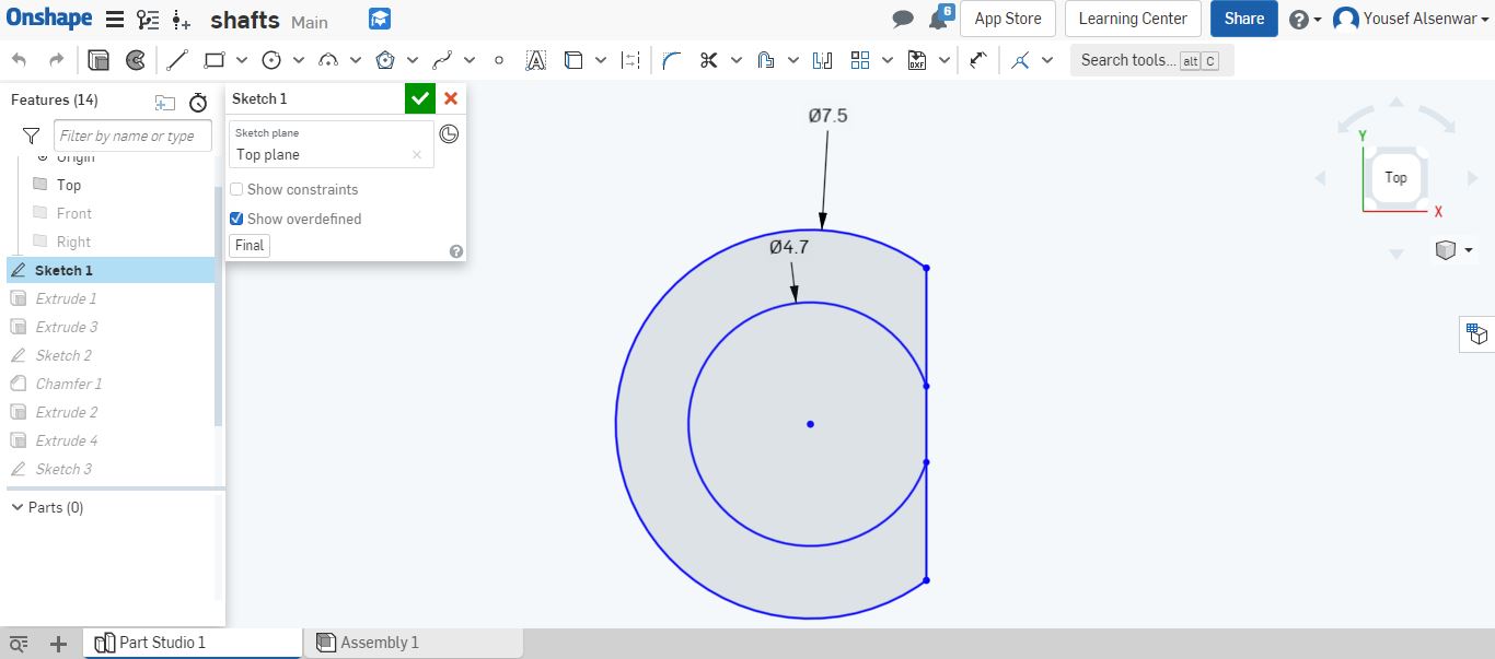
By creating new document in onshape, I started the designing process using sketch tool to do the circle and then extrude it. But I need two circles as the diameter will not be the same for all the length, I had to consider the motor side to ue the coupler. Also, as I’m planning to print the part using 3D printer, it’s difficult to print it like this and without support (the diameter is small as well), therefore, I cut a small part to be printed and strong enough to move
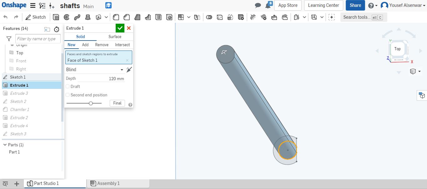
Now, I checked the length of the roll with the side edges to decide the depth of the extrude. Then I clicked on extrude to do the inner circle
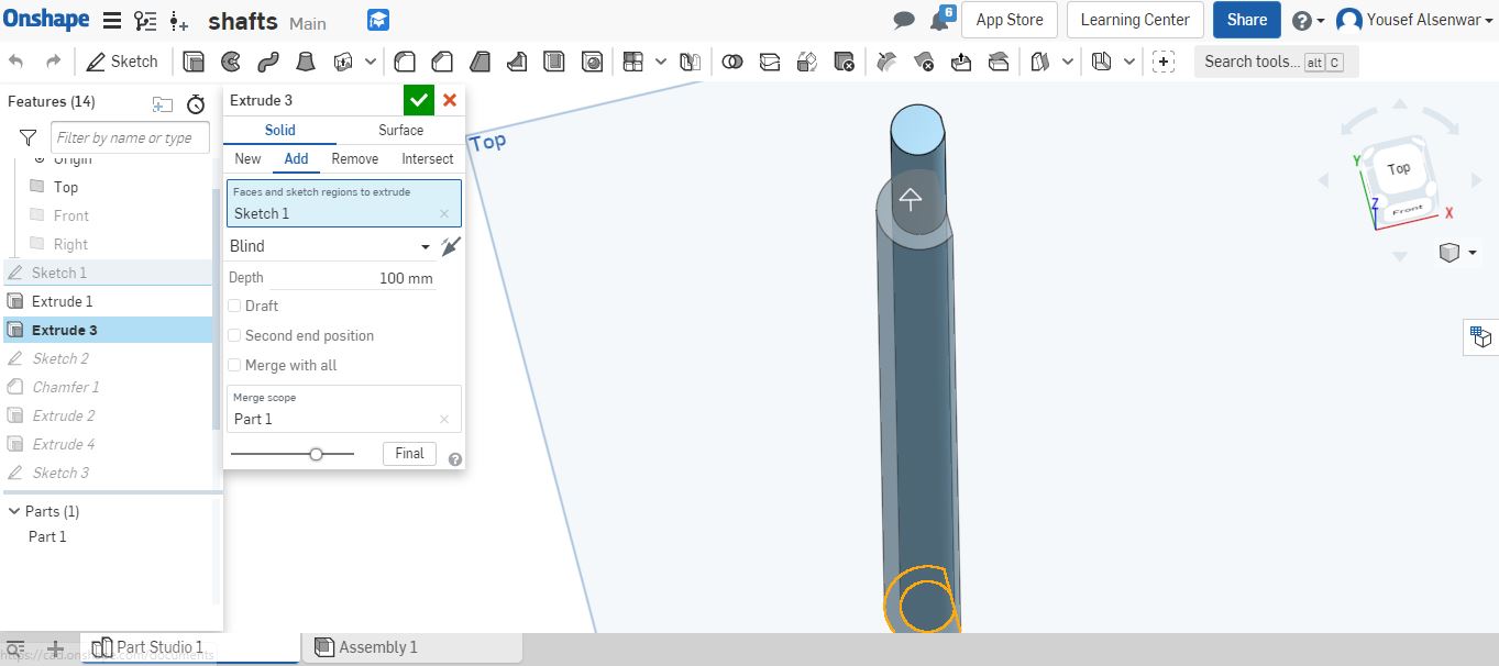
The outer circle should be extruded the same amount of the roll length in addition to the sides
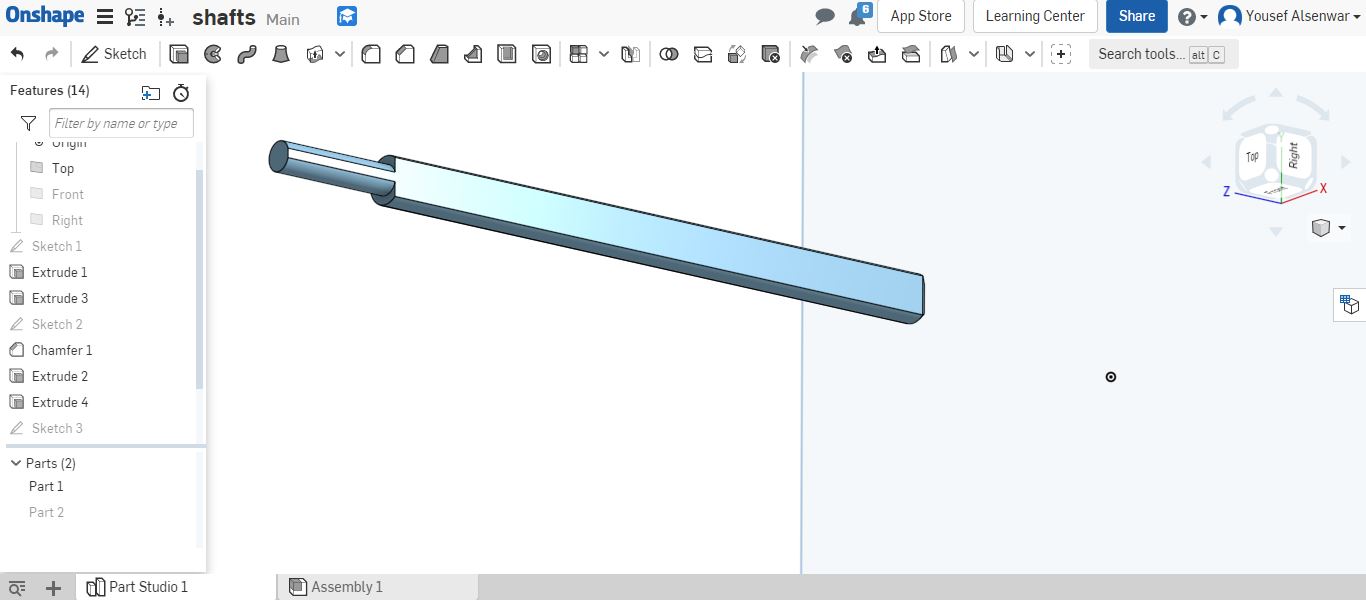
The shaft is ready to export
By exporting the file as stl, I dropped the exported file in PrusaSlicer to get the Gcode and start printing using Prusa 3D printer. I started printing the shaft
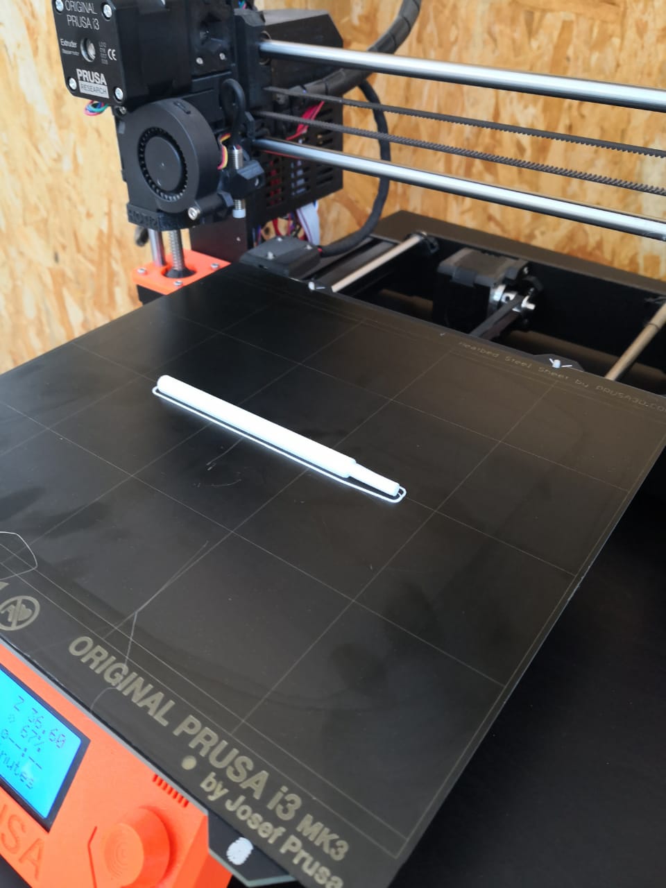
I got the part, the printing is very good and strong enough
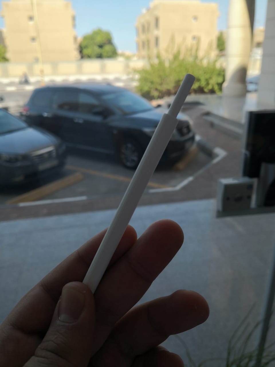
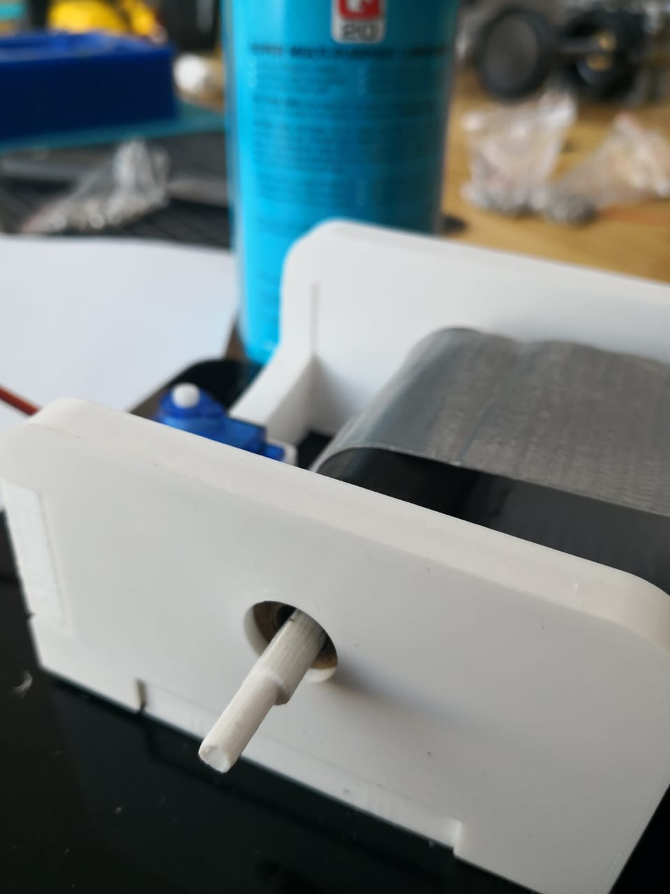
I inserted the part, it was tight enough to move the roll so we can move the belt
Moving into the code side, what I have here is the microcontroller board and 3 main components, which are: Servo motor, DC motor (the driver is power mosfet IRF520), and color sensor
Since the microcontroller bard is not ready, I’m planning to test the code and parts using Arduino at first to make sure that everything is going to be okay. I started testing the DC motor at first, it can be controlled easily using power mosfet driver with protection diode
I used a very useful tutorial that guided me how I should connect the motor using IRF520 transistor. I did connect the circuit
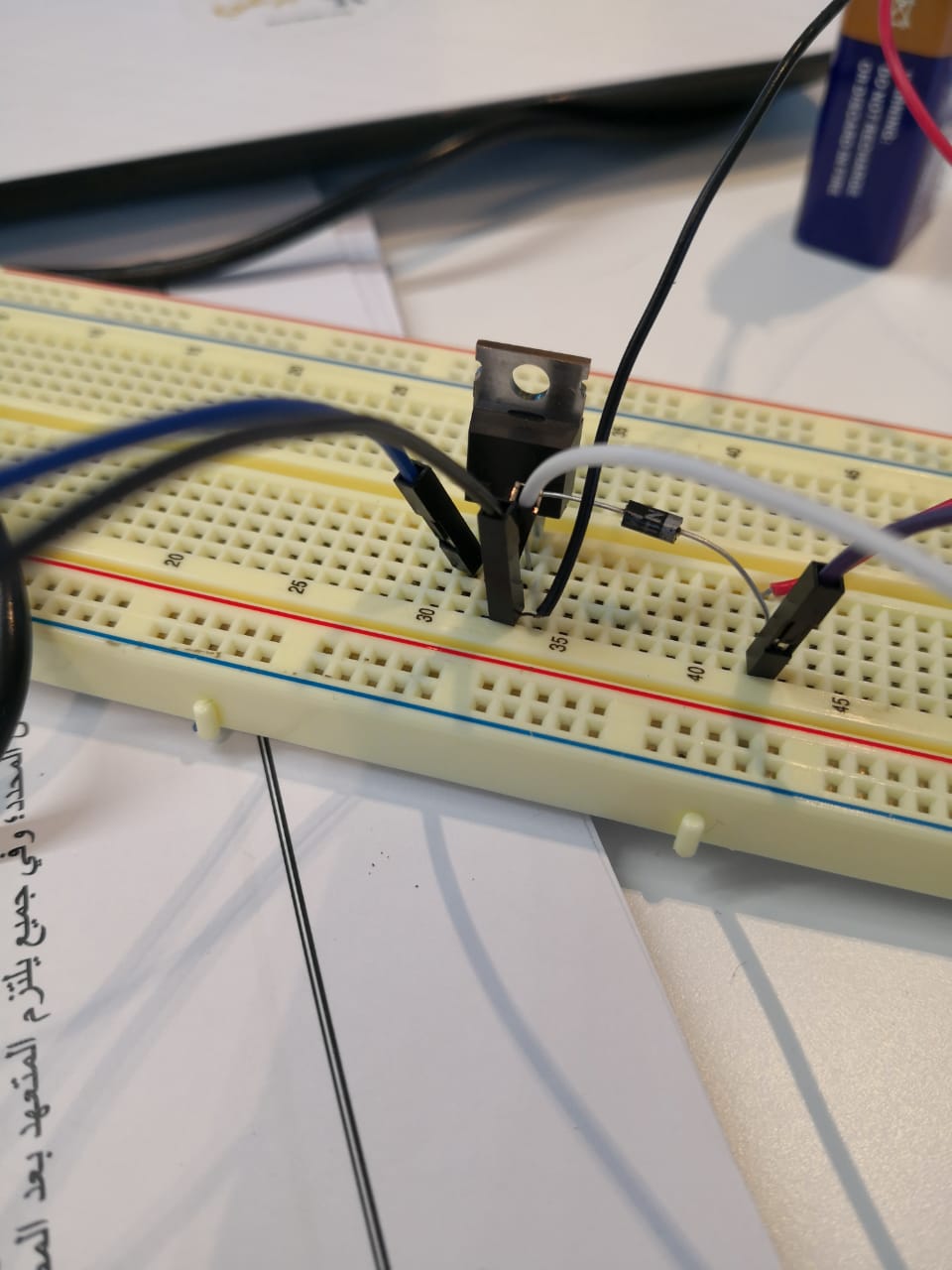
I prepared a very simple code, to check the motor movement, the code is basically sending an analog signal to the transistor, the transistor run the motor accordingly (I used a wall power supply, 5v 3A, as external power supply to run the motor) because the arduino can not provide the current needed, as it can draw 40mA max from I/O pins
void setup() {
  //Selecting PWM pin
pinMode(6, OUTPUT);
}

void loop() {
//the speed can be set from 0 to 255 as max. speed
analogWrite(6, 150);
}
I plugged the usb cable and uploaded the code. The motor moved at speed of 150. It can be max if I changed the value to 255
As the motor worked with the driver (IRF520), I moved to the next step, component which is color sensor. The color sensor that I have is called TCS3200, it has 10 pins, I will use 7 pins
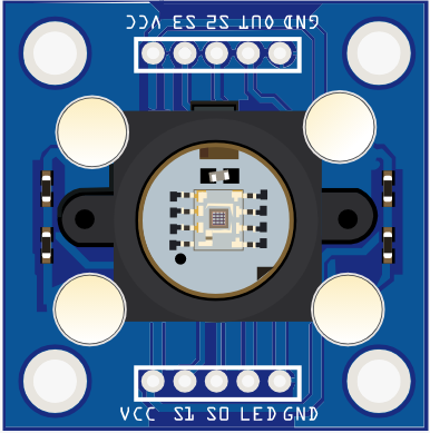
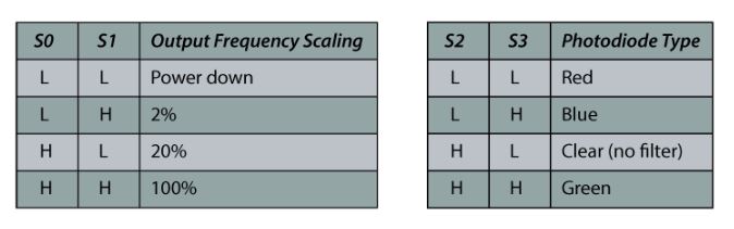
Vcc, GND, S0, S1, S2, S3, and OUT. This sensor contains 8 x 8 array of photodiodes. It has 3 main filters, 16 of photodiodes have red filter, 16 of photodiodes have green filter, 16 of photodiodes have blue filter, and the last 16 have no filter (clear). By using the two control pins S2 and S3 we can select which of them will be capturing the color. And S0, S1 are used for scaling the output frequency. To set the sensor to detect red or green or blue I should follow the following table
I connected the circuit as the following:
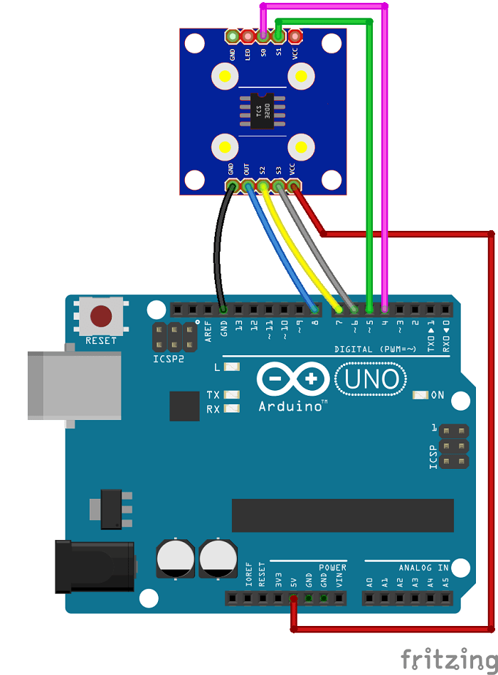
After connecting the circuit, I start preparing the code to read the values of red, green, and blue. So I can know the values for each color I want to detect. In this case, I can use conditions to do something when the specific color is detected. Also, I should set the control pins (S2, S3) for each color I want to detect (red, green, blue) levels
#define S0 4
#define S1 5
#define S2 6
#define S3 7
#define sensorOut 8
int frequency = 0;
int Red=0;
void setup() {
  pinMode(S0, OUTPUT);
  pinMode(S1, OUTPUT);
  pinMode(S2, OUTPUT);
  pinMode(S3, OUTPUT);
  pinMode(sensorOut, INPUT);
  pinMode(6,OUTPUT);

  // Setting frequency-scaling to 20%
  digitalWrite(S0,HIGH);
  digitalWrite(S1,LOW);

  Serial.begin(9600);
}
void loop() {
  // Setting red filtered photodiodes to be read
  digitalWrite(S2,LOW);
  digitalWrite(S3,LOW);
  // Reading the output frequency
  frequency = pulseIn(sensorOut, LOW);
  Red=frequency;
  // Printing the value on the serial monitor
  Serial.print("R= ");//printing name
  Serial.print(frequency);//printing RED color frequency
  Serial.print("  ");
  delay(100);
  // Setting Green filtered photodiodes to be read
  digitalWrite(S2,HIGH);
  digitalWrite(S3,HIGH);
  // Reading the output frequency
  frequency = pulseIn(sensorOut, LOW);
  // Printing the value on the serial monitor
  Serial.print("G= ");//printing name
  Serial.print(frequency);//printing RED color frequency
  Serial.print("  ");
  delay(100);
  // Setting Blue filtered photodiodes to be read
  digitalWrite(S2,LOW);
  digitalWrite(S3,HIGH);
  // Reading the output frequency
  frequency = pulseIn(sensorOut, LOW);
  // Printing the value on the serial monitor
  Serial.print("B= ");//printing name
  Serial.print(frequency);//printing RED color frequency
  Serial.println("  ");
  delay(100);


}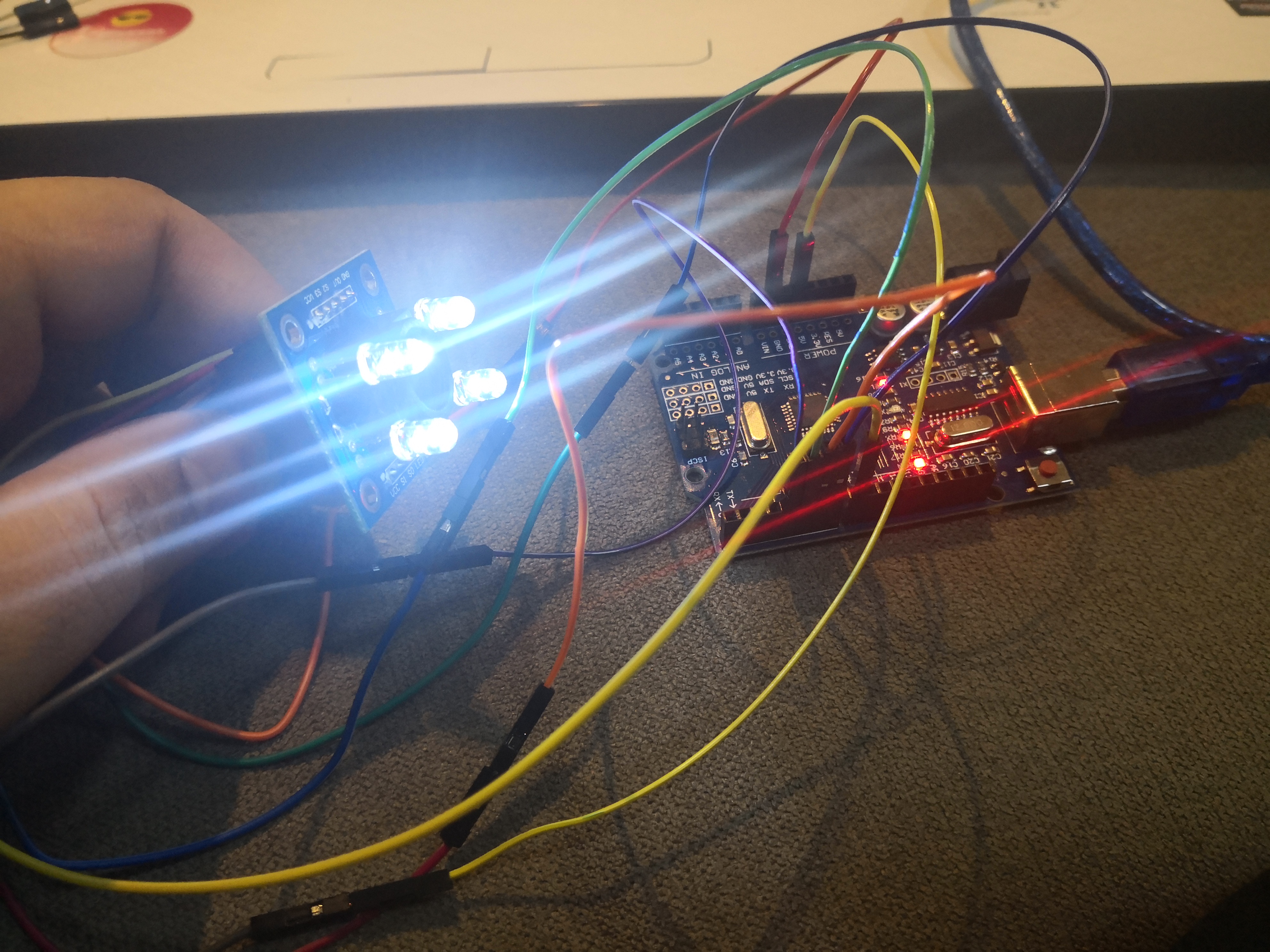
I uploaded the code and tested 3 colors that I have to get the results through serial monitor and keep them up to the next code
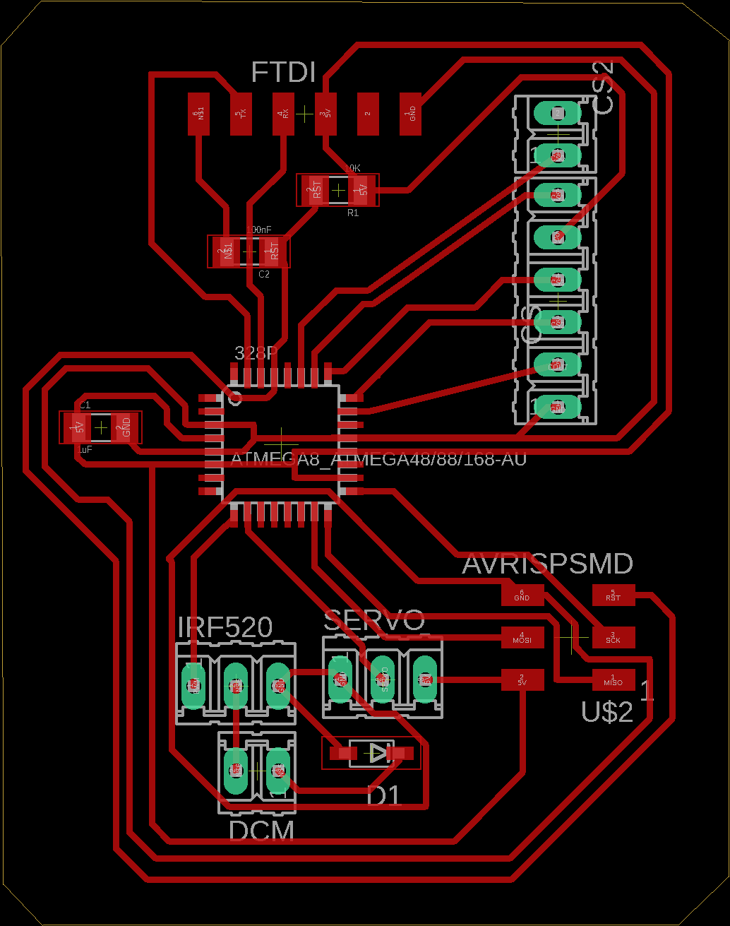
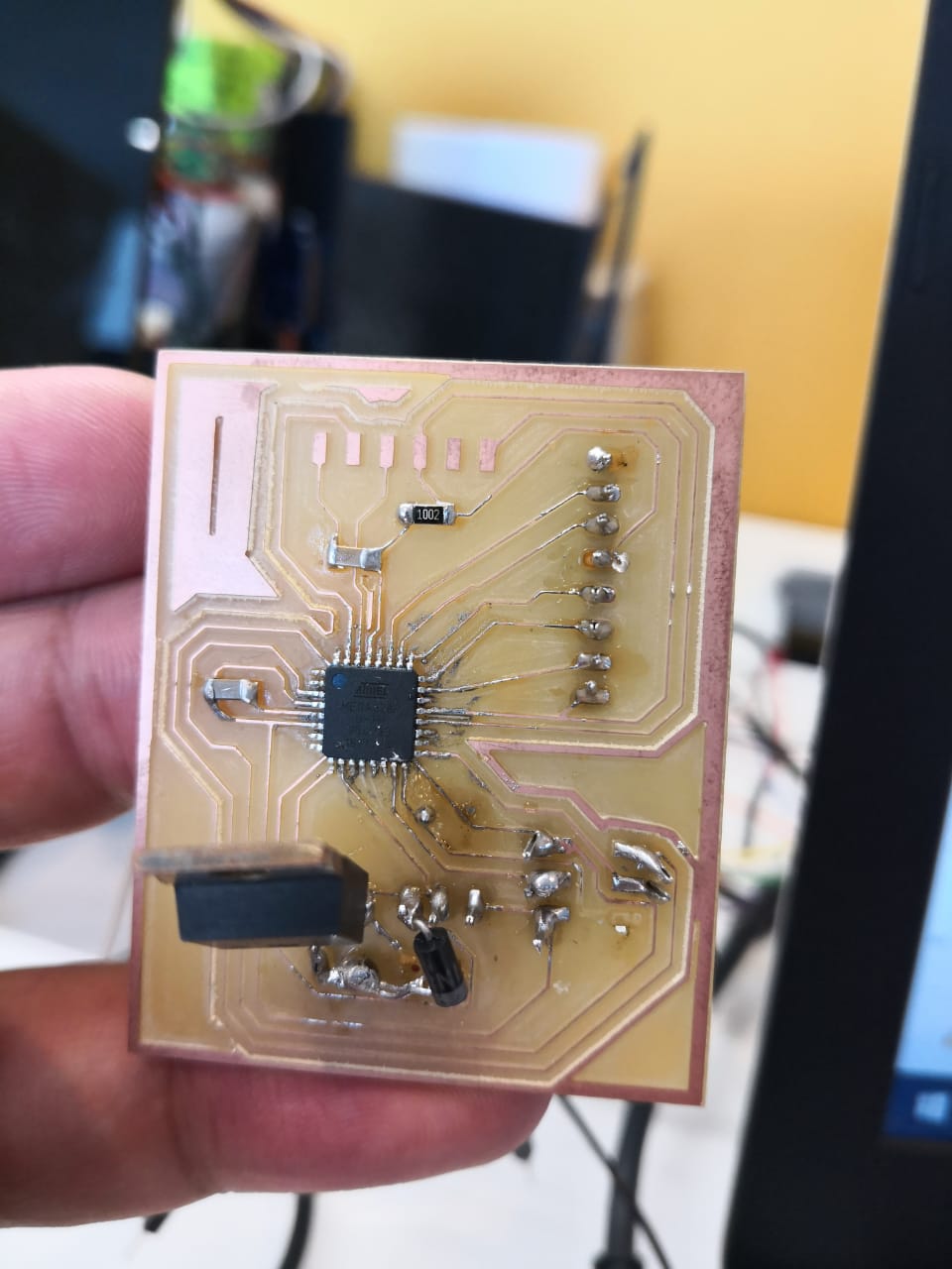
The PCB, microcontroller board is ready. Mass was working on the design
He started milling it using Carvey machine
So, I have to test the components using it. After milling the board, Hussain started soldering it
List of components:
- Atmega328p
- 100 nF capacitor
- 1 uF capacitor
- 10 kohm resistor
- IRF520 power mosfet
- 1N4007 diode
- Headers or cables
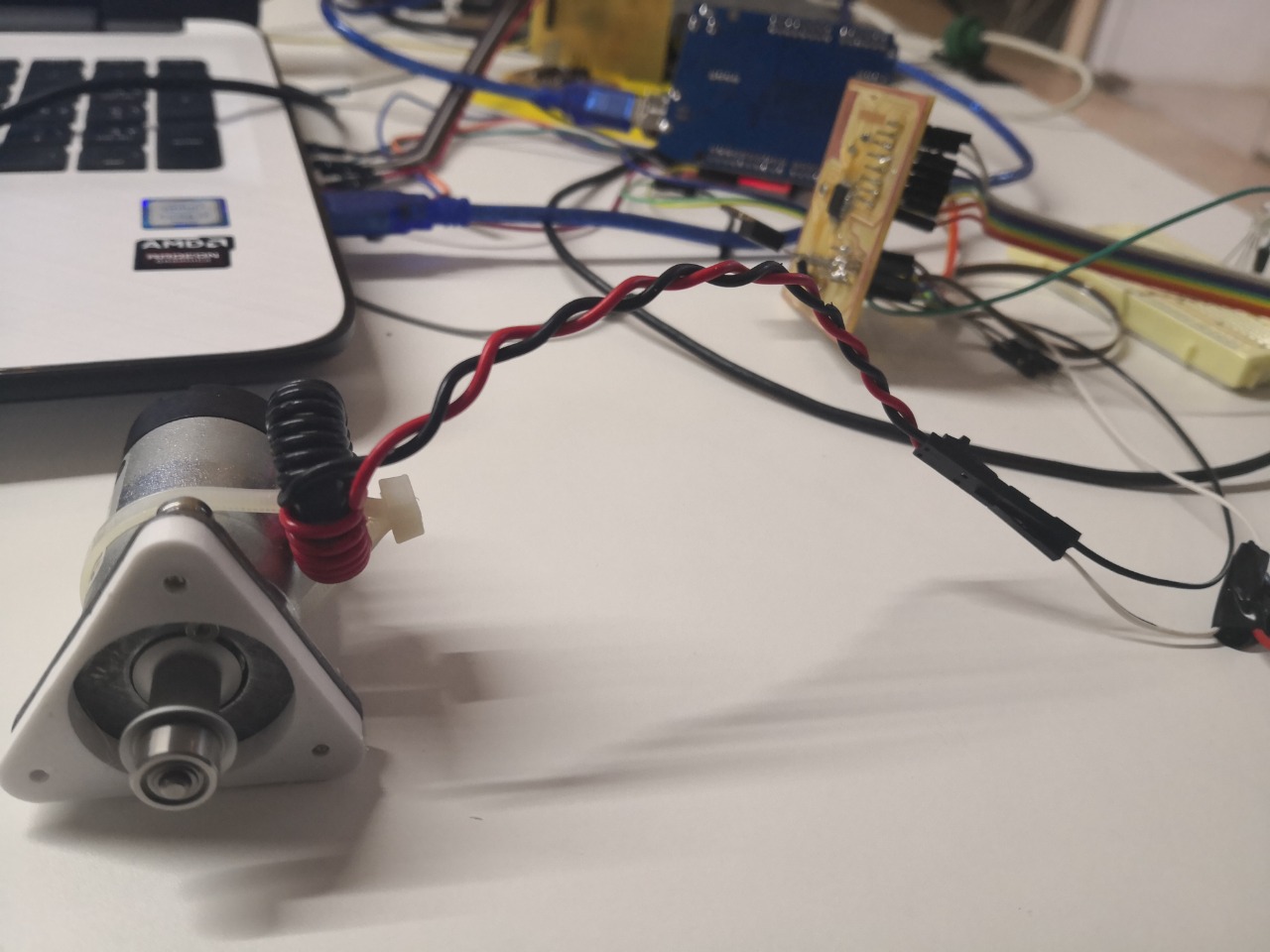
I started testing the DC motor that I’m planning to use in the project. I connected the motor with cables the same place where Mass considered in the board, which is pin # 5. I can get PWM (pulse width modulation) to control the output voltage, therefore, to control the speed of the DC motor
I used the same code that I tested using Arduino before, I changed the pin only, pin 5. I uploaded the code and the motor starts moving
Then I tested the color sensor using the same pins that were considered in the design, I added a simple condition to the code that I used above, which is the RGB LED will turn on if the color sensor detects red color, the code becomes as the following:
#define S0 A4
#define S1 A3
#define S2 A1
#define S3 A2
#define sensorOut A0
int frequency = 0;
int Red=0;
void setup() {
  pinMode(S0, OUTPUT);
  pinMode(S1, OUTPUT);
  pinMode(S2, OUTPUT);
  pinMode(S3, OUTPUT);
  pinMode(sensorOut, INPUT);
  pinMode(6,OUTPUT);
  pinMode(5, OUTPUT);

  // Setting frequency-scaling to 20%
  digitalWrite(S0,HIGH);
  digitalWrite(S1,LOW);

  Serial.begin(9600);
}
void loop() {
  // Setting red filtered photodiodes to be read
  digitalWrite(S2,LOW);
  digitalWrite(S3,LOW);
  // Reading the output frequency
  frequency = pulseIn(sensorOut, LOW);
  Red=frequency;
  // Printing the value on the serial monitor
  Serial.print("R= ");//printing name
  Serial.print(frequency);//printing RED color frequency
  Serial.print("  ");
  delay(30);
  // Setting Green filtered photodiodes to be read
  digitalWrite(S2,HIGH);
  digitalWrite(S3,HIGH);
  // Reading the output frequency
  frequency = pulseIn(sensorOut, LOW);
  // Printing the value on the serial monitor
  Serial.print("G= ");//printing name
  Serial.print(frequency);//printing RED color frequency
  Serial.print("  ");
  delay(30);
  // Setting Blue filtered photodiodes to be read
  digitalWrite(S2,LOW);
  digitalWrite(S3,HIGH);
  // Reading the output frequency
  frequency = pulseIn(sensorOut, LOW);
  // Printing the value on the serial monitor
  Serial.print("B= ");//printing name
  Serial.print(frequency);//printing RED color frequency
  Serial.println("  ");
  delay(30);

  if (Red < 60){
    digitalWrite(6, HIGH);
    analogWrite(5,255);
  }

  else{
    digitalWrite(6, LOW);
    analogWrite(5,0);
  }
}
The RGB LED was connected with pin 6. The test was perfect and the system runs accordingly
We have attached the motor and test the whole system in terms of mechanical movement
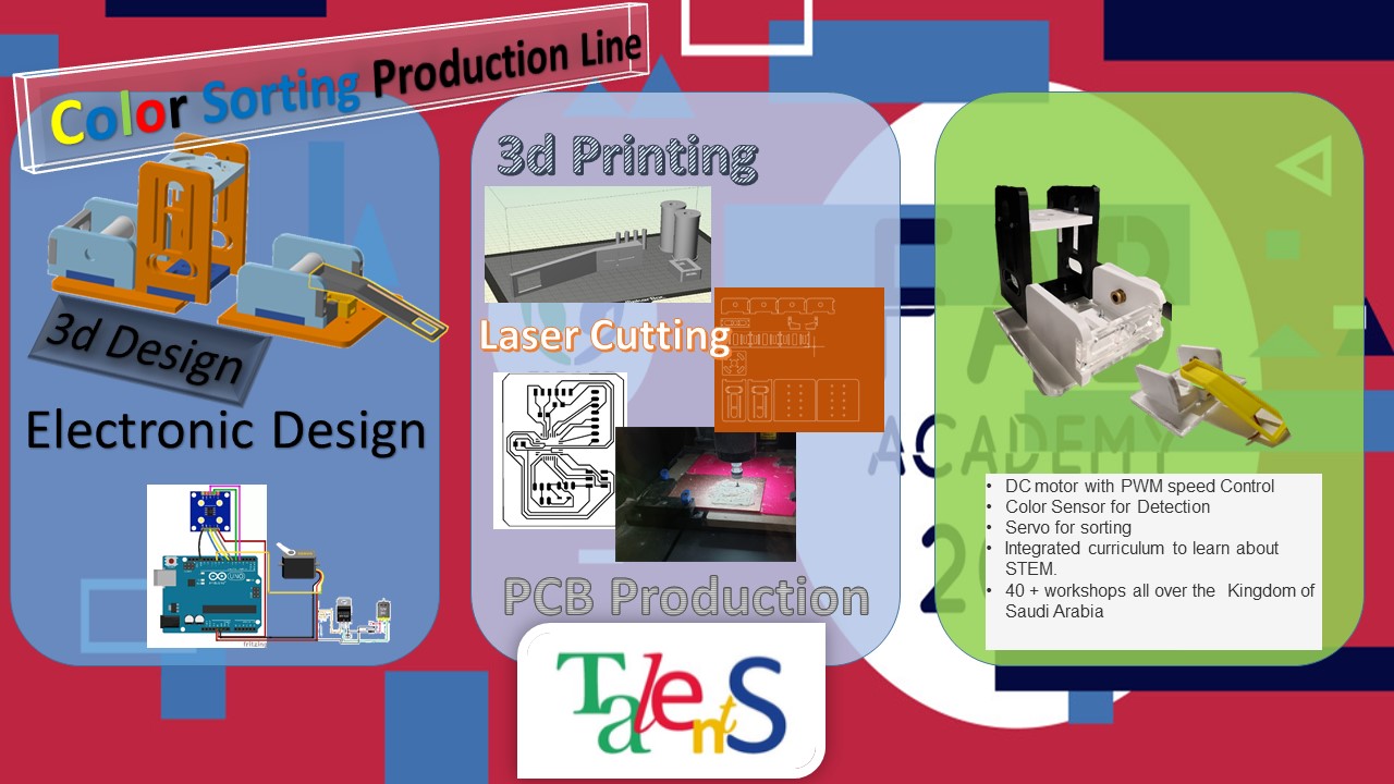
We prepared the poster and video for the presentation
Download Files' Links:
Color sensor with DC motor code