Week 15: Mechanical Design
Individual assignment
This week we will work on a team plan to make a CNC machine. We need to analyze and solve technical problems, also recognize opportunities for design improvements.
CNC Machine
The mechanical part of a CNC machine will be designed and assembled, with the help of the CIT director, the essential parts were obtained to be able to make the machine.
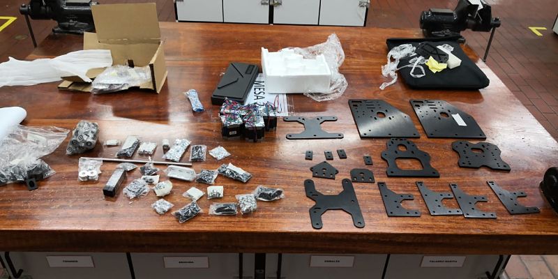 Fig.01 - CNC Components
 The pieces that can be modified easily are the plates to obtain a greater height in the CNC machine and the length of the V-SLOT that will reach a meter and a half.
The pieces that we will use without modifying will be the hardware, spacers and motion components.
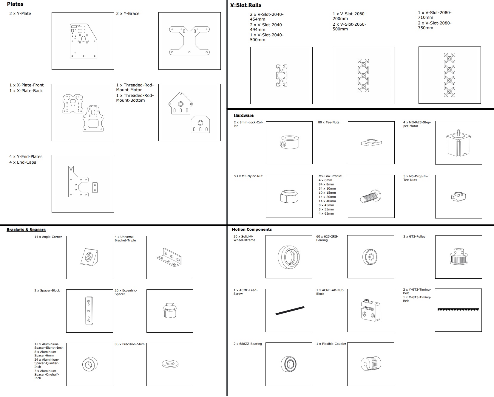 Download CNC Pieces
 Fig.02 - CNC Components
CNC Design
Once agreed the measures with the members of the CIT, I designed the 3D model of the CNC that we are going to build to obtain referential measures and observe possible problems that we will have in the future during the assembly.
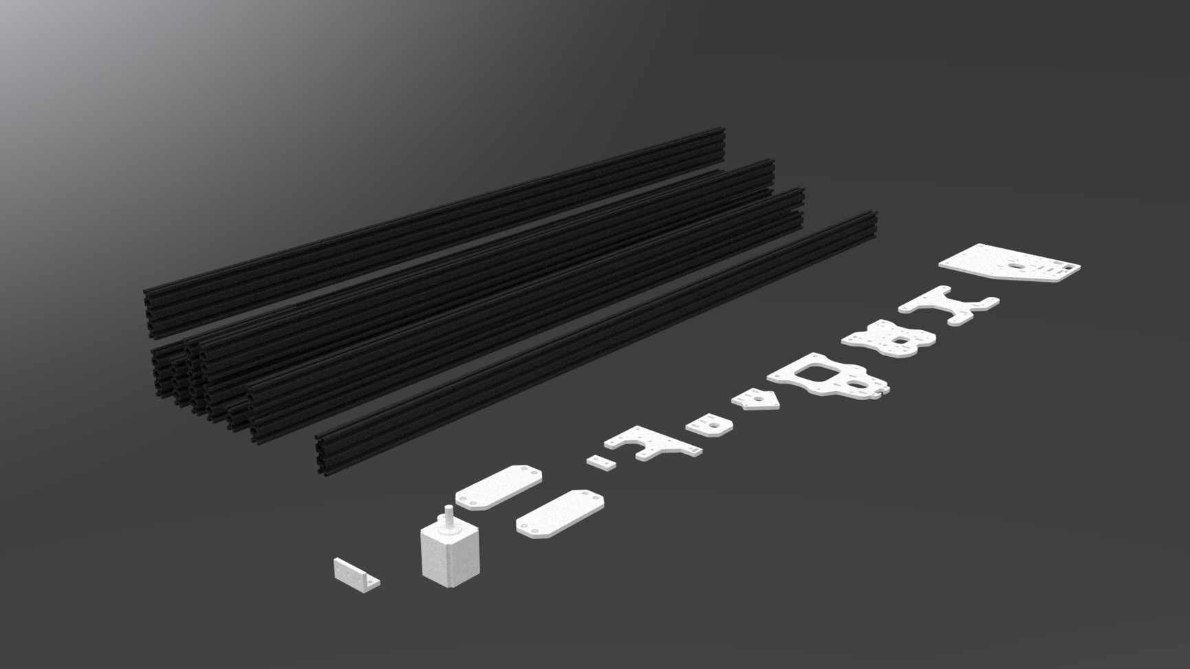 Fig.03 - CNC 3D Components
 Once the pieces were assembled, this would be the possible result of the machine that we are going to build in the CIT.
The stand of the machine was designed in rhino, it used two times that were fastened on the Z axis. This is a machine that has the function of subtracting material. Observe the 3D printing in the Makerbot + printer, the parameters that were increased were the following: Support (20%), filling (75%) and balsa (10 mm).
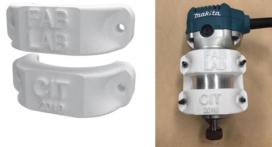 Download Makita STL file
 Fig.05 - Makita
In order to cut some pieces in 5mm stainless steel, the CIT plasma CNC machine was used. It has a control panel that allows to modify the parameters.
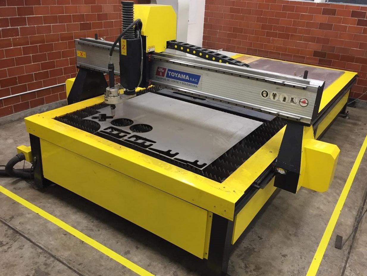 Fig.06 - CNC Plasma
 The software of the CNC plasma cutting machine is Libellula Wizard, it is very easy to use, unlike the other software that took me time to learn like the multicam or the roland model.
As you can see in the image, we generate a new file and insert the file dxf. Then, add the address where the file will be saved and click on the "next" option, this will create the g-code, which will open in the control panel of the plasma CNC.
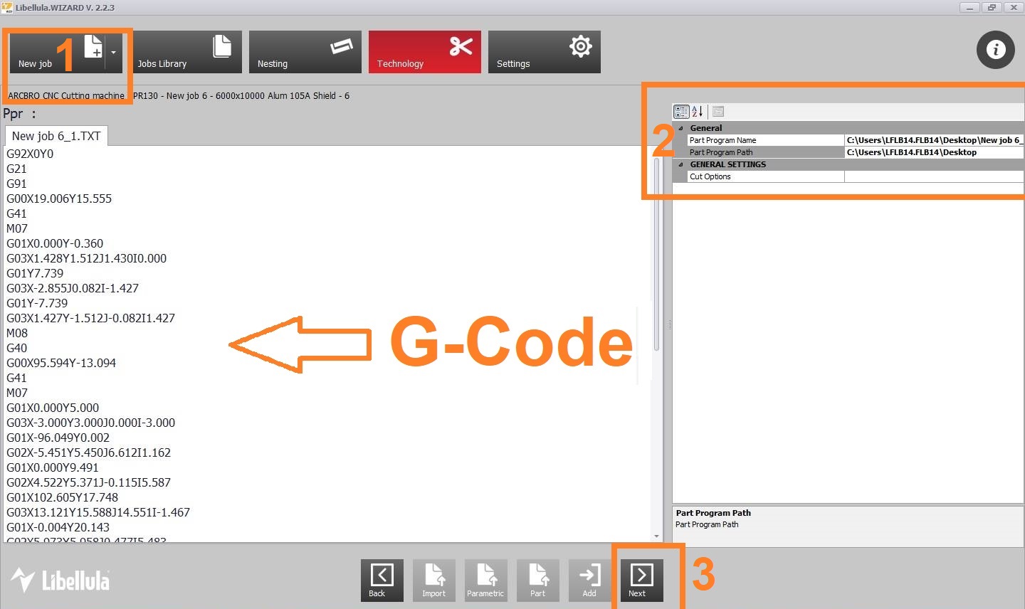 Fig.07 - Libellula Wizard
 The following parameters were set in the control panel: speed (2500 mm / min), amperage (80A) and air pressure (70 PSI)
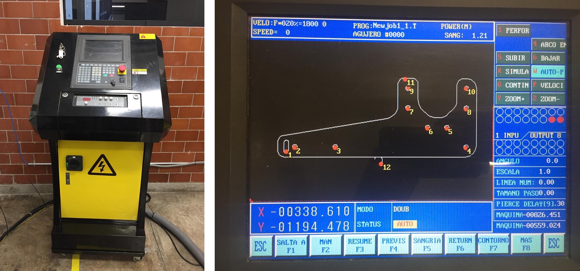 Fig.08 - Control Panel
 If the code-g was successfully exported, the machine will be able to cut the piece in a few seconds. The use of dark glasses and the use of gloves is recommended.
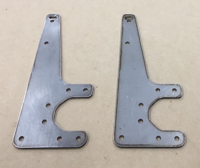
The result is a 4xY End Plate pieces modified in height, in this way it would be possible to cut future materials with greater height and thickness in the Z axis.
 Download STL file
 Fig.10 - 4xY End Plate
In the armed group, with the members of the CIT: Italo Pratolongo and Edwin Alvarez the X-Y-Z axes of the CNC were assembled, the MDF base and the electronic part.
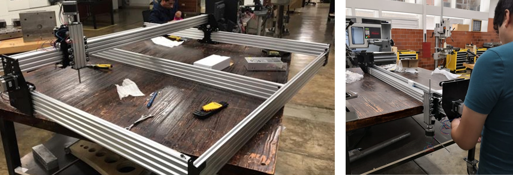 Fig.11 - Assembly of CNC parts
 To see all the documentation of the group work, you can visit the CIT page.