Week 11: Input Devices
Individual assignment
This week we had to design, make and schedule a board that allows us to use an input to read something. I will control the closing of my coverage through light sensors, which are applied in my final project.
Data Sheet
Sensors are devices that interact with mechanical, electrical, magnetic and thermal variables. It is a device that detects external stimuli and transforms them into electrical signals that are received by the microcontroller.
In the FabLab CIT we will find some analog type signal sensors like the following: Acceletometer ADXL 343B that reads acceleration and vibration, Microphone that captures sounds, LM35 that reads temperature, Thermistor 10k that reads temperature using a resistor, Hall sensor that captures the position, LDR that captures the amount of light and finally, the Ultrasonic sensor that reads the distance using the sound.
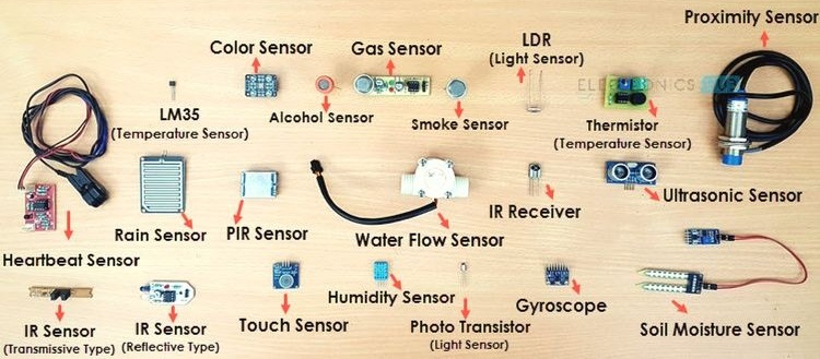 Fig.01 - Sensors
 I will use a light sensor, which I will adapt in the coverage of my final project. This will control the closing of some materials that allow the entry of light into the pavilion. For this, it was necessary to know the data sheet . The sensor has some analog, digital and electrical characteristics. It was necessary to know the operation and the quantities of the LDR voltage to make programming work.
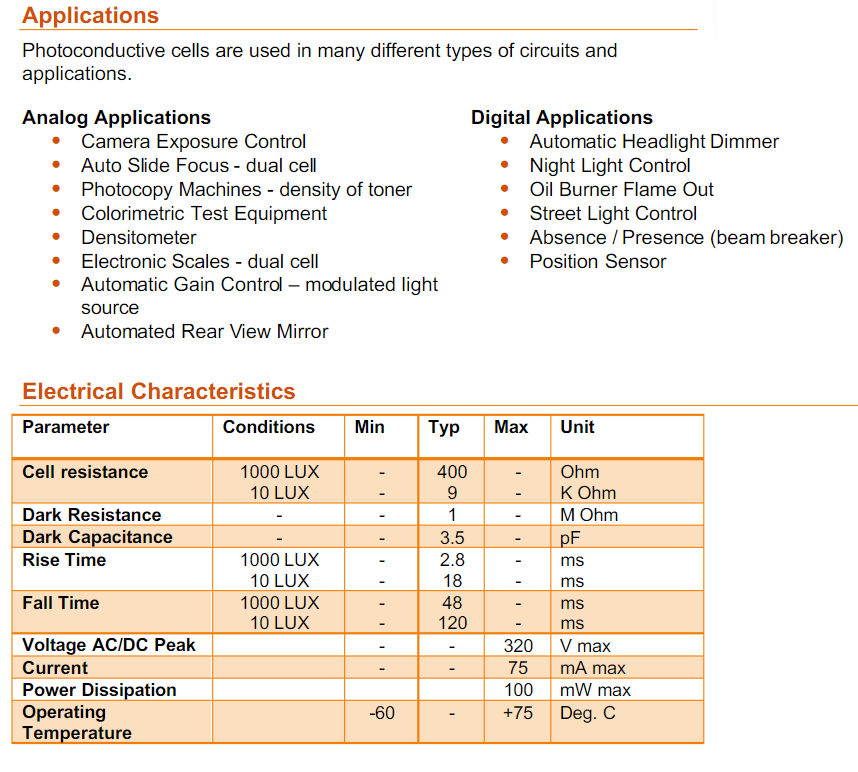 Fig.02 - Data Sheet LDR
 Analog Digital Converter (ADC)
The ADC contains a Sample and Hold circuit which ensures that the input voltage to the ADC is held at a constant level during conversion.
The ADC converts an analog input voltage to a 10-bit digital value through successive approximation. The minimum value represents GND and the maximum value represents the reference voltage. These values are within the microcontroller ranging from 0 to 1023, representing 0V and 5V respectively.
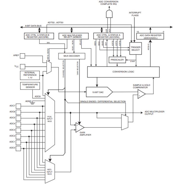 Fig.03 - ADC
 PCB Design
I will continue using the Attiny44 for the assigment development, since I got a little more familiar with the digital and analog pins.
I added the light sensor with an LED to see if it was turned on or off when programming it.
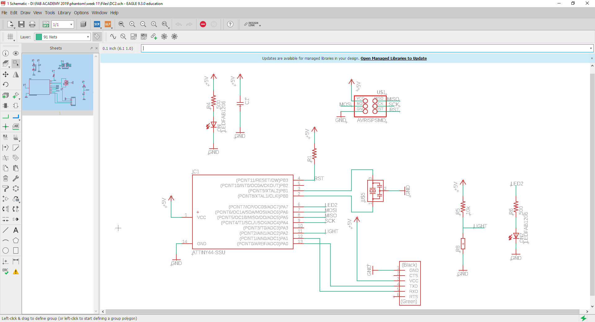 Fig.03 - LDR Sensor Schematic
 Once I finished my scheme I started with the design of my board, since I did not have a SMD photoresistor in the laboratory I will use a conventional one. You can appreciate the symbology on the board.
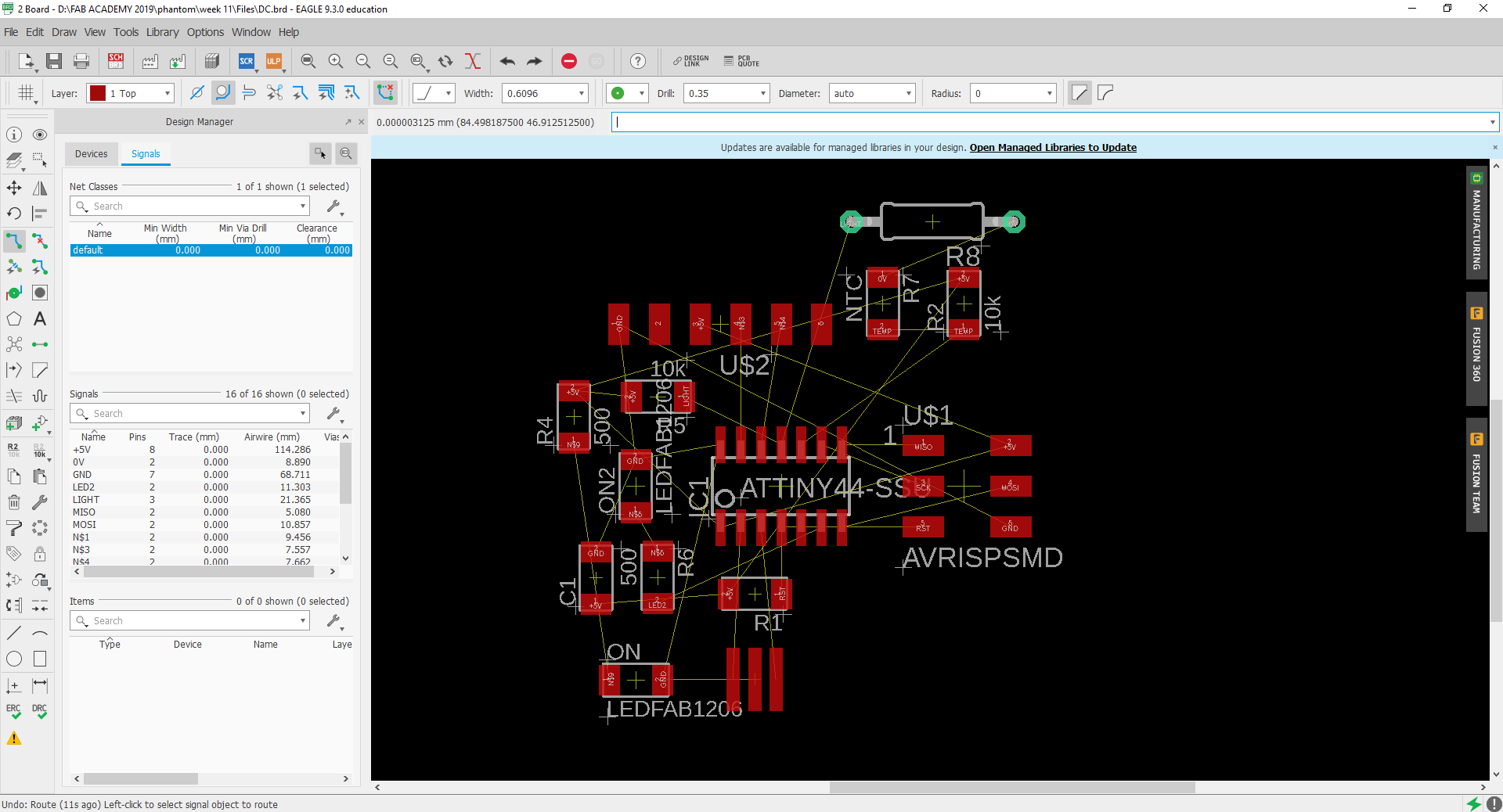 Fig.04 - Board
 It took me a little time, but I managed to connect all the routes.
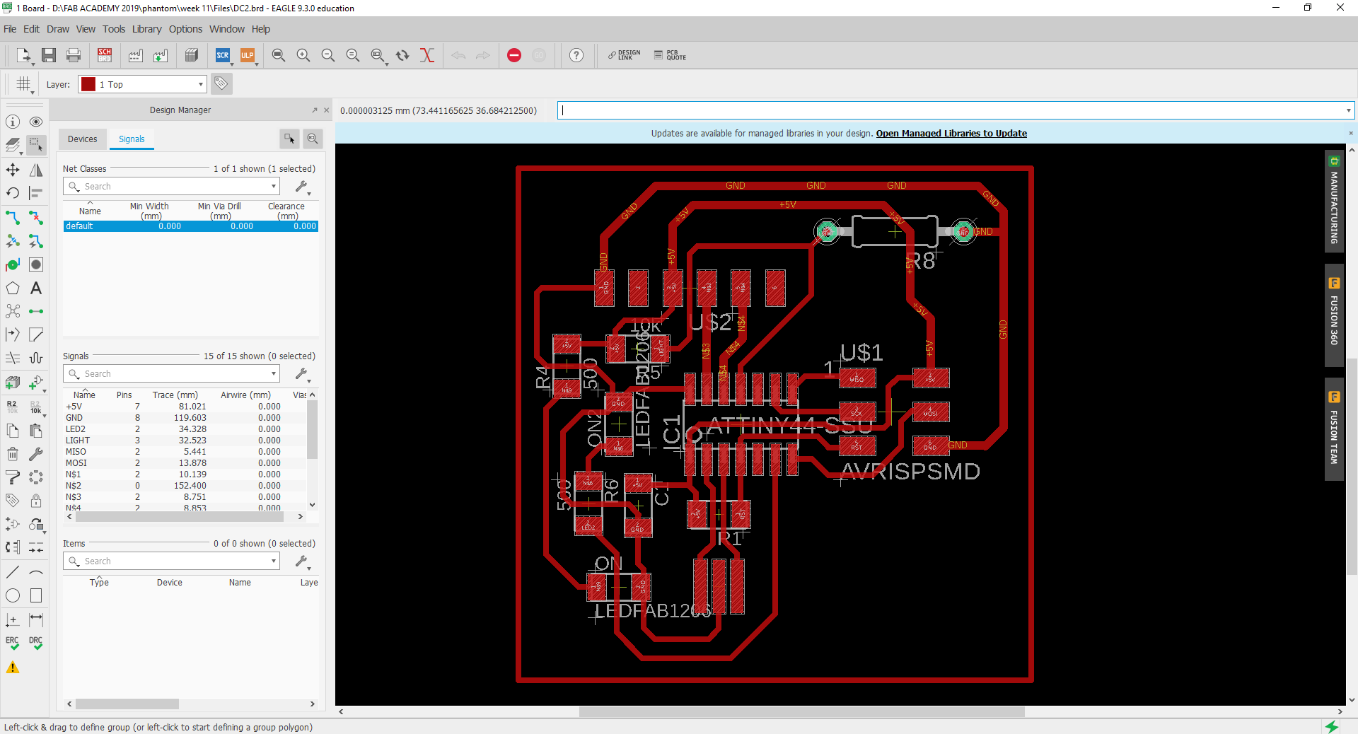 Fig.05 - Route connection
 I exported the image in PNG, I was very careful when creating an intermediate route in the AVRISPSMD pins.
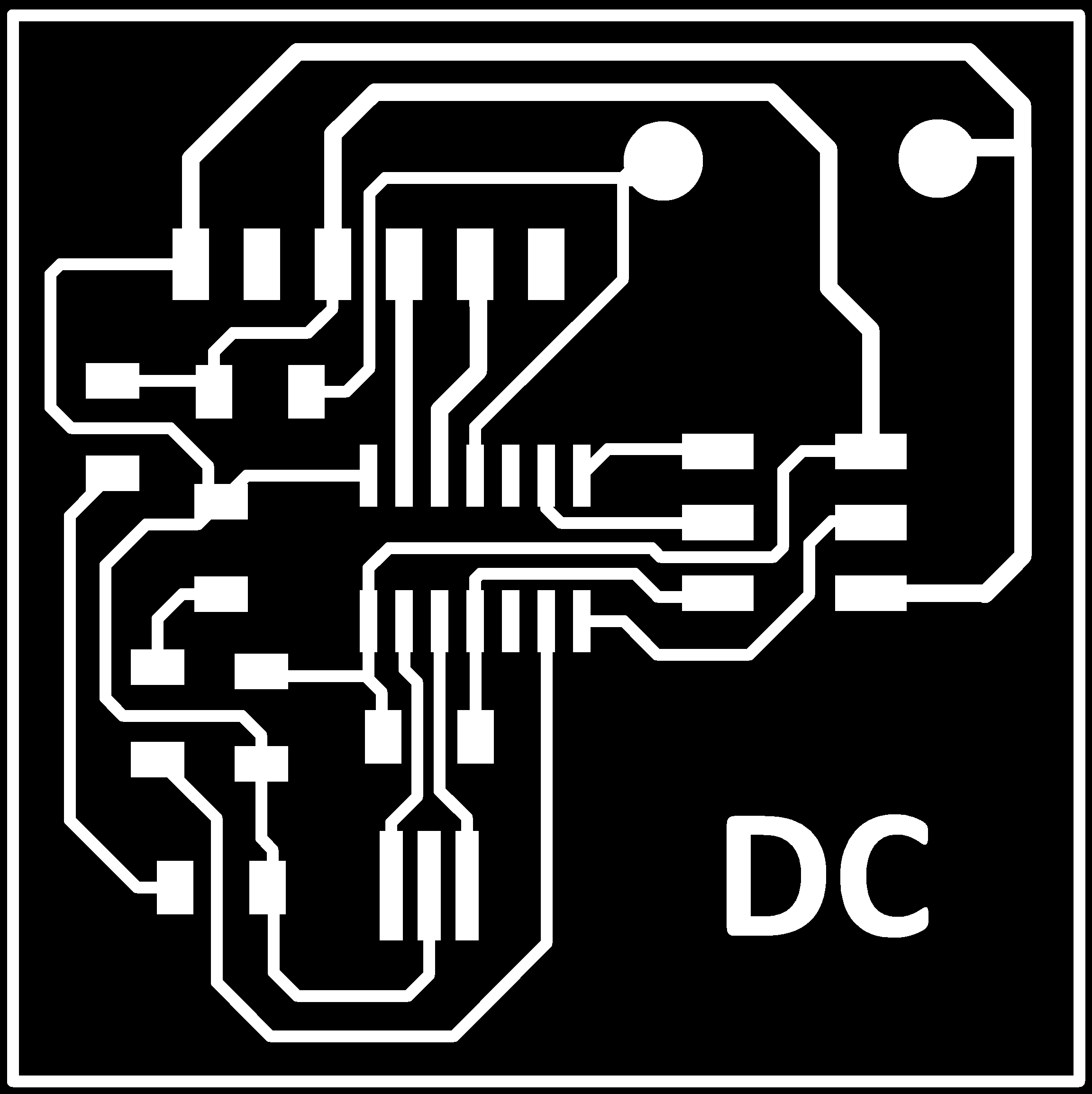 Fig.06 - PNG
 In the Web page Fab Modules I will generate the code g, this time I will increase the number of offsets to 15 to have a greater separation between routes, this way I will have a better work area when using the flux.
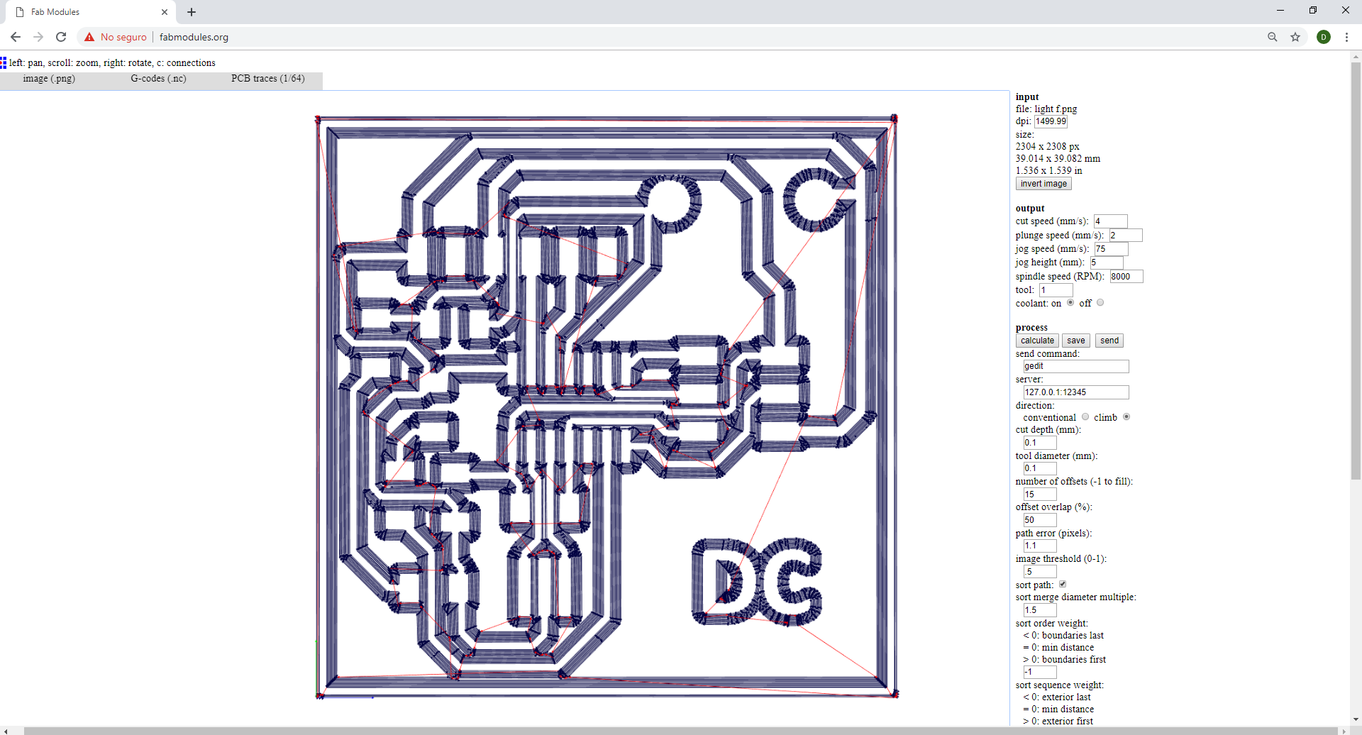 Fig.07 - Code G
 After cutting it at the CNC, I verify that the routes are complete. This process I carry out with the multimeter. However, I have generated holes in the location of the LDR, this will allow me a better stability when using the flux.
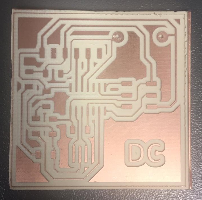 Fig.08 - DC Inputs Board
 After soldering the components, the final result is observed in the image. I tried continuity with the multimeter and we are ready to program it.
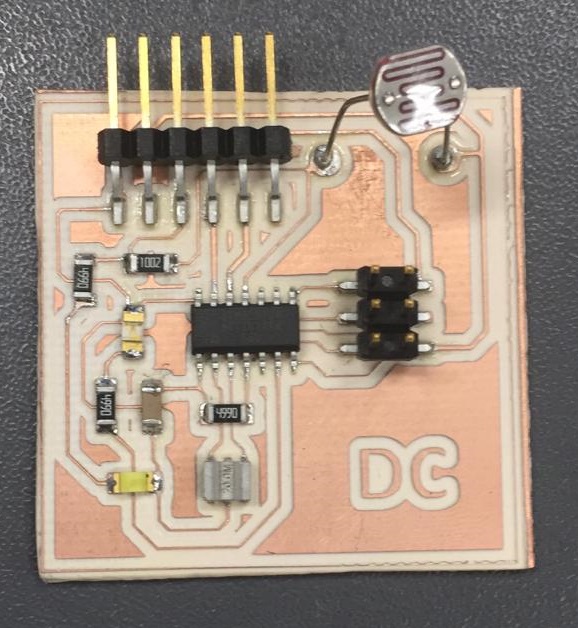 Fig.09 - DC Inputs Board
 Programming
I used my ISP board to record the boot manager, it worked the first time, it did not generate any errors. I declared my variables and according to the data sheet I tried to define LED the turn on with a voltage lower than 90 and the LED to turn off with a voltage greater than 150. Finally, the programming was uploaded.
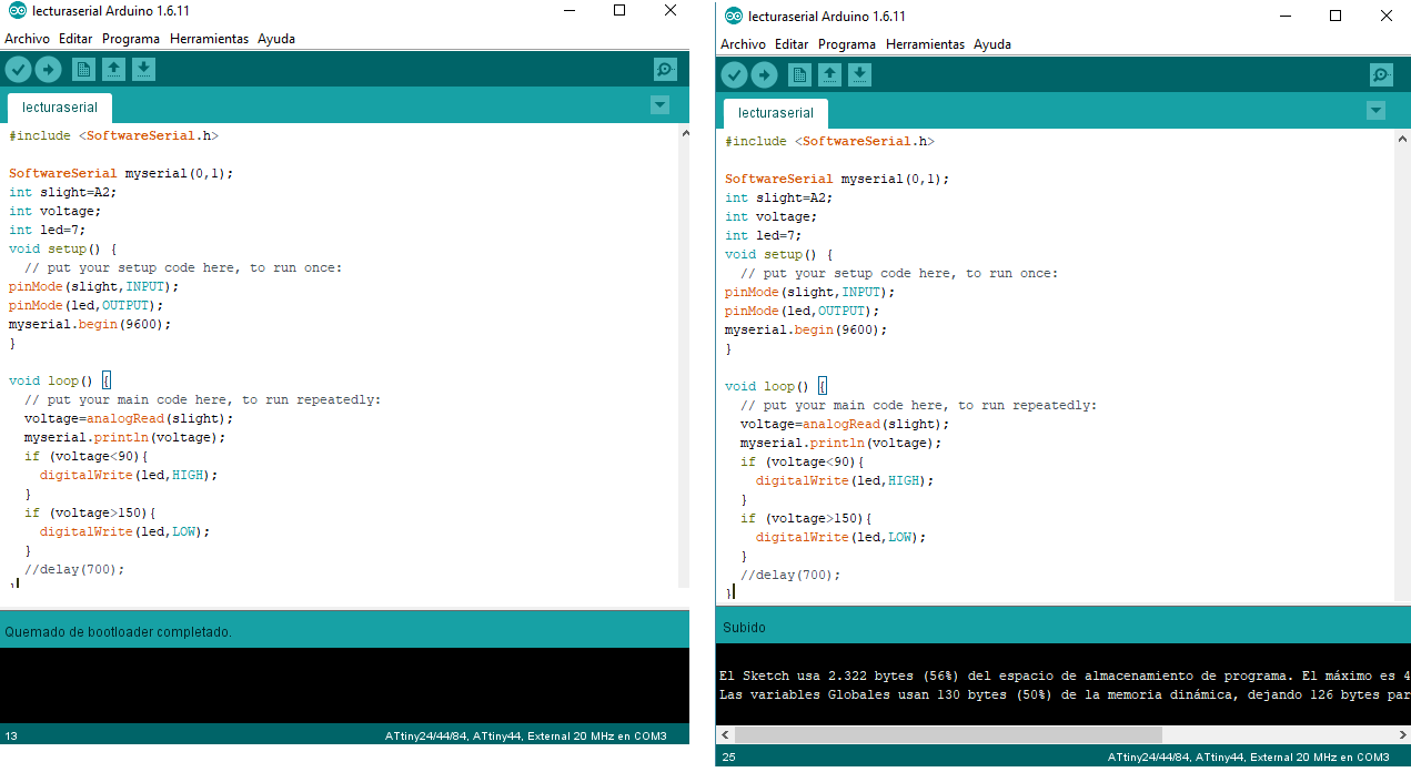 Fig.10 - Programming uploaded
 In the gift, we can observe the connection of the programming components and how to cover with a finger the LED of the sensor goes off and when it is removed it is turned on again.
Files
You can download group files here.
Arduino CodeSchematic & Board
PNG
Group assignment
A input board was created with two inputs, one of the analog type and another of the digital type.
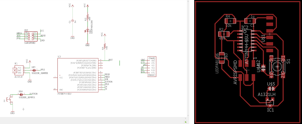 Fig.12 - Sch & Board
 Programming and measurement Button
The first example we are going to use is the pushbutton, as shown in the schematic, we do not use a resistor to create the pull_up configuration, but we will use the internal configuration of the pinMode directly with the following simple code.
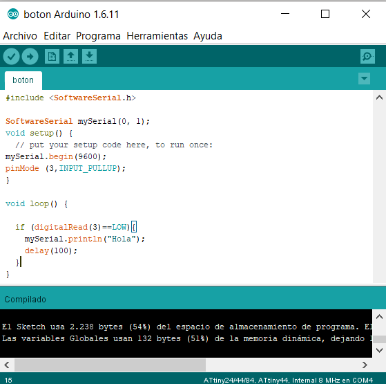 Fig.13 - Sch & Board
 Taking advantage of the welding bridge created near the button, we proceed to connect the multimer to measure voltage and current according to the following scheme .
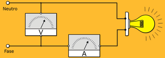 Fig.14 - Scheme
 Proceed to perform the measurements as they are seen in the images: Voltage (When pressing the button, we have a voltage of 4.95V and if we do not keep it pressed it gives us a voltage of 0V) and Current (In this case the measurement always gives 0A since, having only the button and with the internal configuration as pull_up, there is no opposition of electric current as could be caused by an electrical resistance, for this case the current will be measured by an analog sensor).
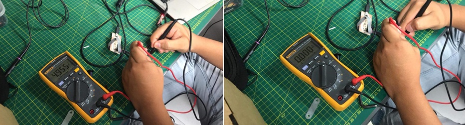 Fig.15 - Voltage & Current
 To perform a new current test, i will use the LDR input sensor, the measured current values are as follows: LED OFF (28mA), LED ON (46mA).
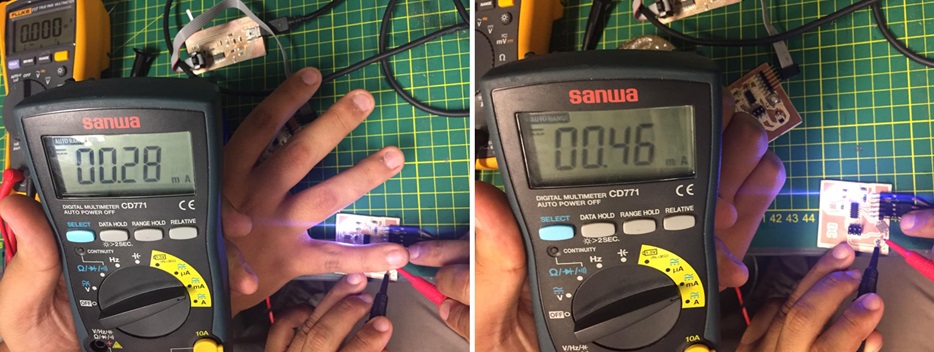 Fig.16 - LDR Current Test
 To see all the documentation of the group work, you can visit the CIT page.
Group Files
You can download group files here.
BoardButton