Week 4: Computer - Controlled Cutting
This week I learned how the use of computer-controlled cutting machinery, more specificly laser cutter and vinyl cutter machines.
Individual assignments
Pametric press-fit construction design
For the Pametric press-fit construction I will use the Rhinoceros program with the Grasshopper pluggin. In this opportunity I will create a geometry based on polygons with lace slots that fit with the main design. For the development of the design it is necessary to have installed the pluggin grasshopper, which is downloaded from the web page grasshopper3d.com Once the interface is installed when the pluggin is run from the toolbar, an external screen will appear. (Fig.1)
 Fig.01 - Rhinoceros & Grasshopper Interface
 I elaborate the construction diagram that is based on the number of sides of a polygon and the size of the slot. To explain it use name instead of icons in the domain entries, group and color the diagram.
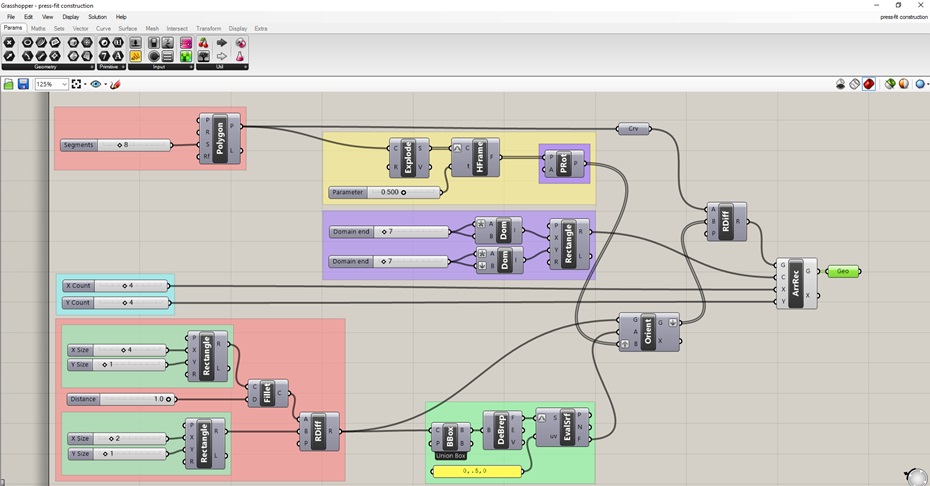 Fig.02 - First Design
 I generate inputs as the parameter of creation of a polygon, for this it is necessary to create a number slicer that controls the quantity of sides
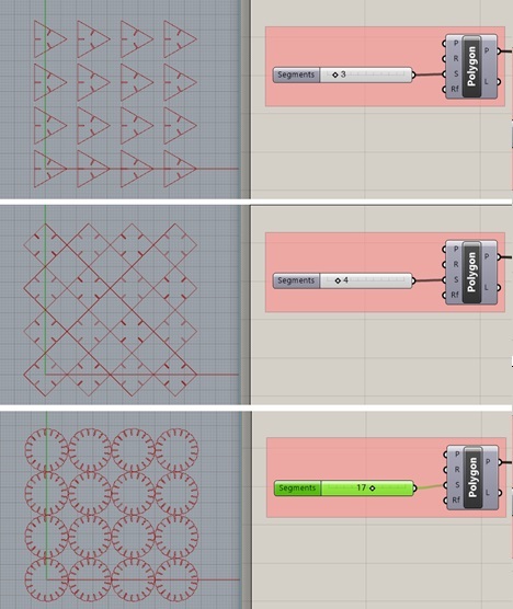 Fig.03 - Sides of a Polygon
 In this geometry, I want the slots to be rectangular. For this, I generate a parameter of length by width in a rectangle, which will be the measure that the material to be used will have.
Try to create slots with chamfer, but create an algorithm that adapts to the different geometries defined in the file, I still can not find the way to generate it. However, it occurred to me to create something similar, with a "Filet" type slot controlled by a slicer. To do this, I use the Region Difference command and I generate a slot controlled by width (x axis) and height (y axis)
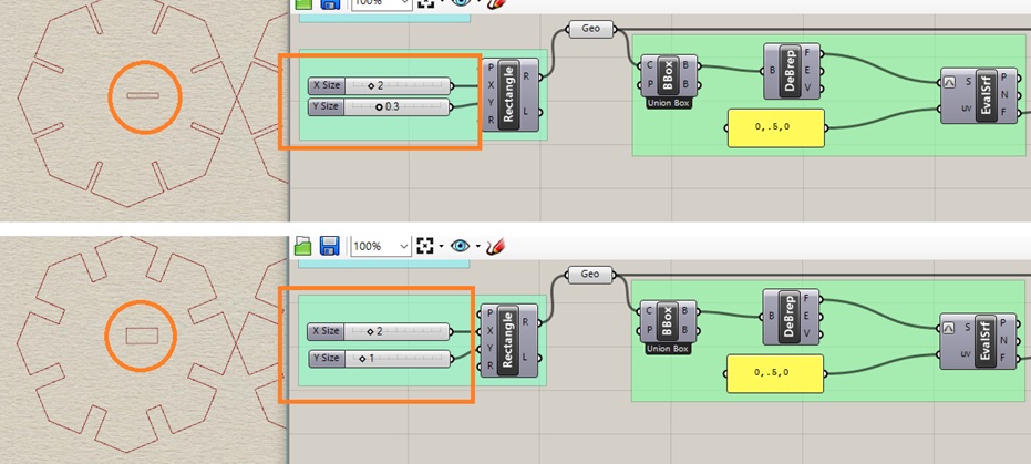 Fig.04 - Slot Size
 To generate a rectangular array that has objects in rows and columns that form a rectangle. I need to create a control cell, which allows to locate the elements to cut them to laser.
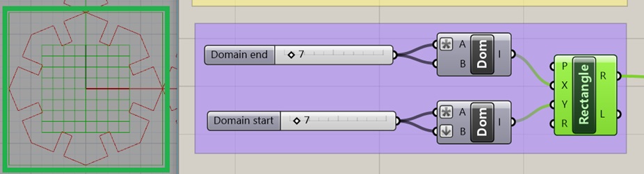
Fig.05 - Rectangular Array Cell Control
For the Array domain and the layout of pieces to cut, it is enough to create an X - Y counter. Finally, attach the design to a geometry box to export without difficulty
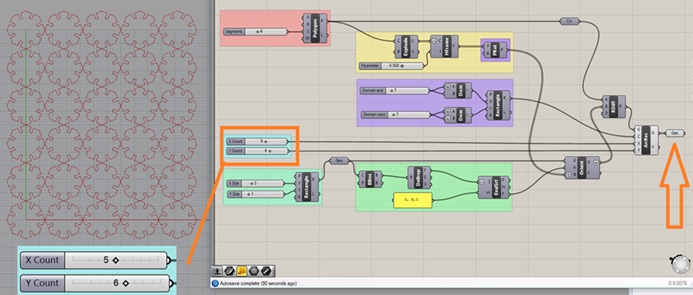 Fig.06 - Count Slicer
 To have the geometry in rhinoceros, you need to right click and look for the "Bake" command.
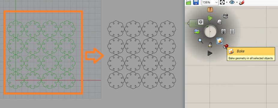 Fig.07 - Bake Tool
 I realized that there were still pieces to be made with Chamfer's pattern. Eliminate the fillet patterns and reduce the slider for better control. It took me some time, what I did was join two geometric subtractions, in this case a square and a triangle.
To do this, I direct the evaluation of the geometrical surfaces in the directions of the segments of the original polygon. Subsequently, subtract the regions to generate the final result.
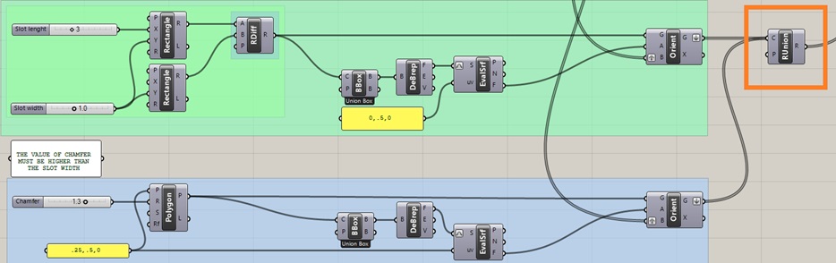 Fig.08 - Parametric Chamfer
 The final result is presented in the following organization of parametric elements. It controls, the amount of distribution by X, Y axes.
In addition, the length of the slot and the width to build it in any material. The angle control of the chamfer must be greater than the width of the slot so that the figure to be extracted is formed.
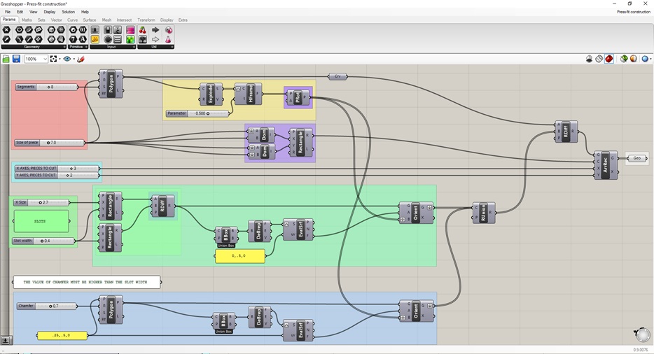 Fig.09 - Final Design Grasshopper
 With these parameters we control the thickness of the material. To build it, click on bake and is ready to laser cut. In this case, I chose the material thickness of 0.4mm corresponding to the corrugated cardboard and a height of 7cm.
Finally, do not forget in what steps you work if it is inches, millimeters, etc. and to open the design with .gh extension it is enough to drag the file to the grashhopper pluggin window.
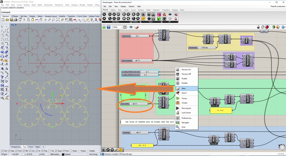 Fig.10 - Thickness of the material
 Download GH Files
Lasercut
The Epilog Fusion M2 32 Laser has a table of 812 x 508 mm and the great quality of engraving that is maintained throughout the table is the result of its components of the highest quality, high speed servomotors and the exciting optional features of double source and camera to read registration points
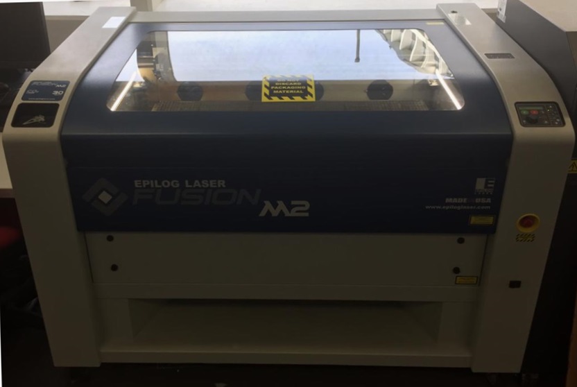 Fig.11 - The Epilog Fusion M2
 The CO2 valve opens, to work in a comfortable environment and to prevent the material from generating fire
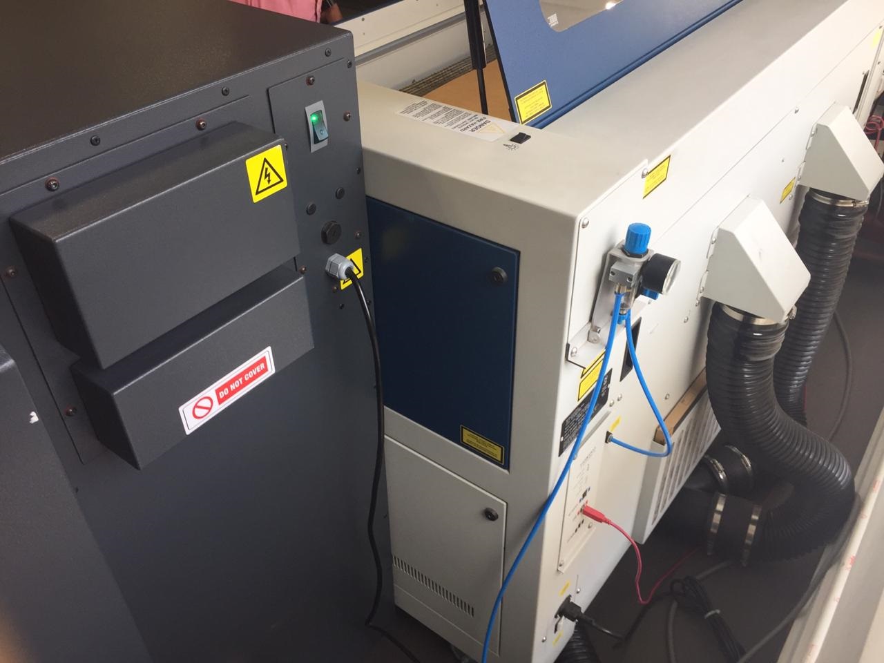 Fig.12 - CO2 valve
 Set the zero point as seen in the picture. When engraving irregularly-shaped objects, Epilog's moveable home position feature will quickly become one of your favorites!
At the push of a button on the control panel you can disable the X and Y motors. With the Red Dot Pointer turned on, move the carriage by hand so that it is placed at you new home position. Press the "Set Home" button and you're done!
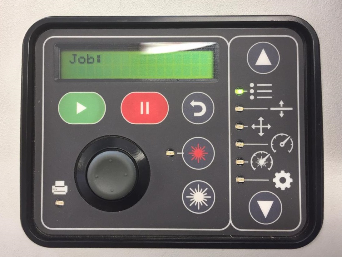 Fig.13 - Control panel
 With this tool we make sure to calibrate correctly
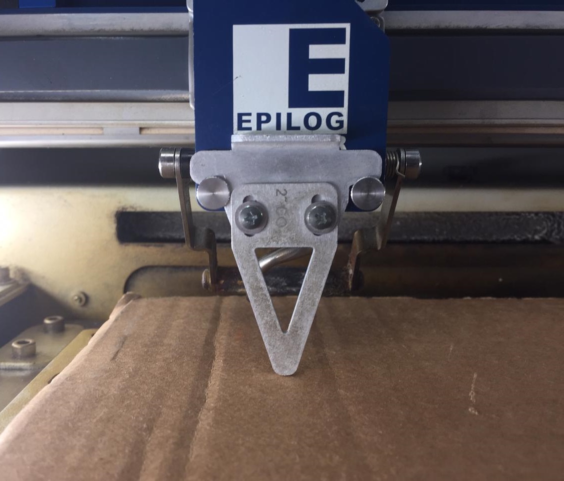 Fig.14 - Calibrate Tool
 Then we export our file designed in the .dxf format
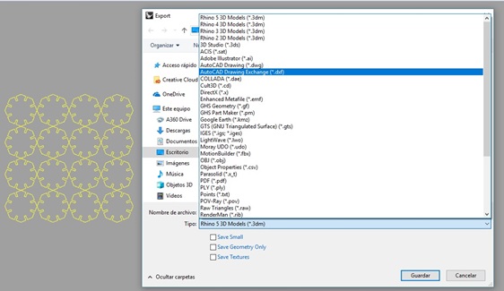 Fig.15 - Export File
 Open the illustrator and place the image, then use the ctrl + P commands to print and select the correct laser cutter
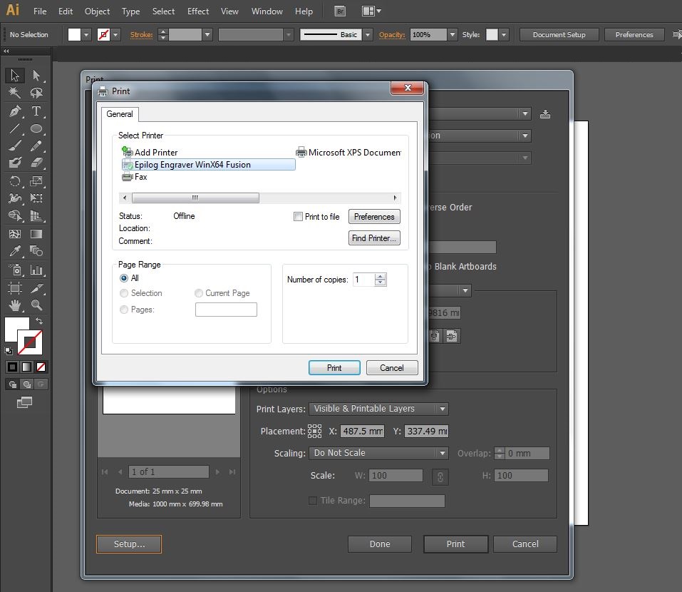 Fig.16 - Select Printer
 We set the printing preferences, in this case we will choose vector setting and we will use 20 speed and 100 power
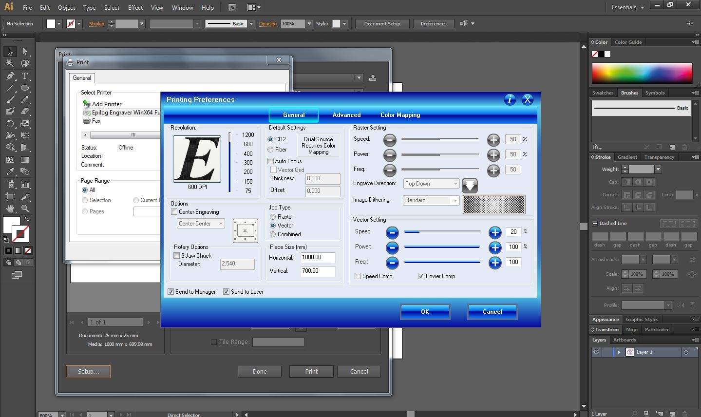 Fig.17 - Printing Preferences
 Now, the laser cut the work
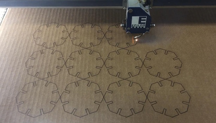 Fig.18 - Pieces
 The project can be assembled in multiple ways.
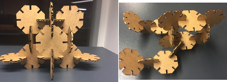 Fig.19 - Pametric press-fit construction
 Lasercut Grasshopper Image sampler
Work in a raster design by parameters, in this case the domains will be the pixels of an image.
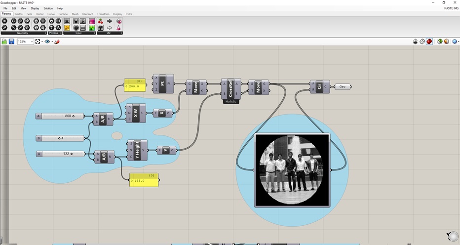 Fig.20 - Grasshopper Image sampler
 We give right click to image sampler, we configure the range of data that would be the divisions between the cross references
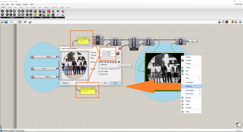 Fig.21 - Image sampler setting
 To generate the design, use the "bake" command and as a result it will appear in the established layer.
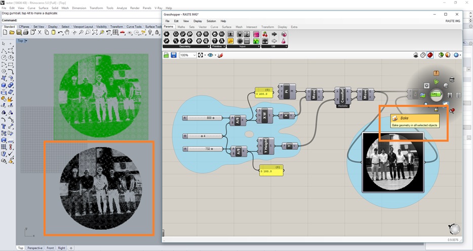 Fig.22 - Bake Tool
 Download GH Rastering Image Files
Once created the file to be cut, we configure the raster option and the dithering image would be "Stucky" to generate gray scale.
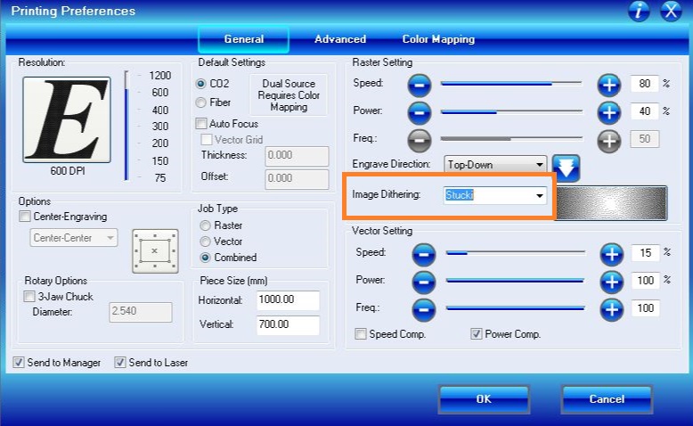 Fig.23 - Printing Preferences
 This is how an image created from parameters that generate circles and form the design
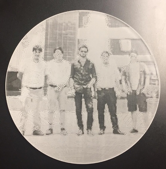 Fig.24 - FAB LAB CIT Image sampler
 Lasercut Raster Illustrator
Insert an image to generate grayscale
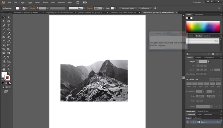 Fig.25 - Place Image
 For my first cut use 5MM MDF
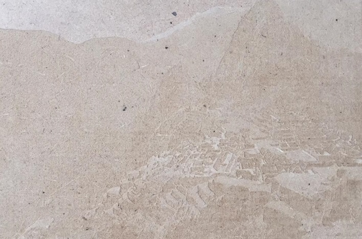 Fig.26 - Lasercut MDF
 When seeing the first result, my tutor recommended me to cut in plywood and the result was amazing
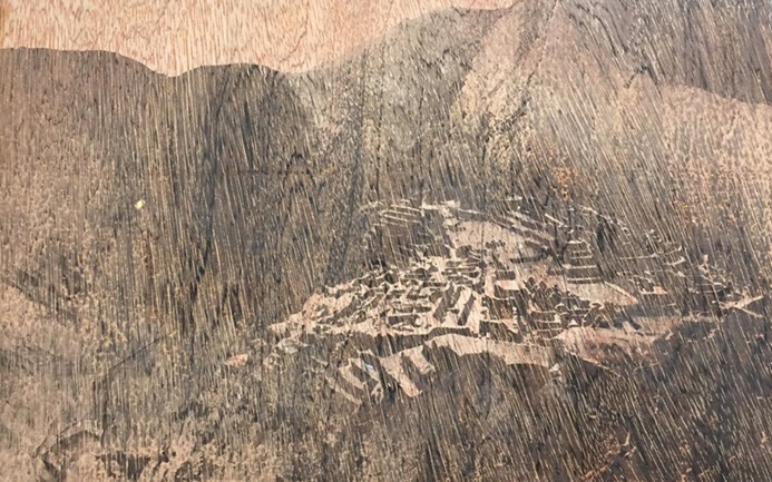 Fig.27 - Lasercut plywood
 Download Lasercut plywood Image Files
Lasercut Raster Rhinoceros
The rhinoceros program was used, in this case we use the picture frame command to send the cut, we designed the letters of FAB ACADEMY ULIMA 2019. Through the design it could be affirmed that it generates a greater quantity of grays and they are evident in the final design.
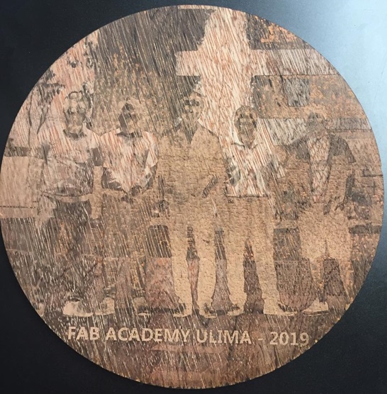 Fig.28 - Picture Frame Image sampler
 Download Picture Frame Files
Vinylcutter
In the laboratory of FabLab CIT we have the Cameo vinyl cutter, for the test of the machine I will cut a logo of a game.
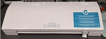 Fig.29 - Vinilo Cameo
 As the first objective was to recognize all the components of the machine, we will find as extra components an electricity cable, a usb cable, a cutting blade cross, a cutting map, knife and a tool removal.
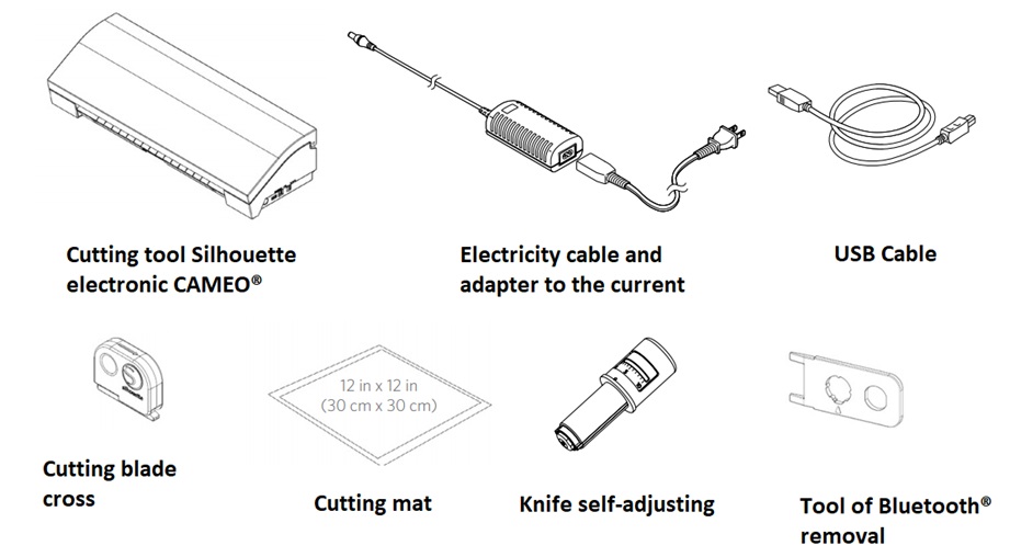 Fig.30 - Cameo Components
 The advantage is the connection and the portable size of the machine, it can be moved from one environment to another and interact with laptop or CPU. The interface does not have a big difference between the operating systems of windows or mac.
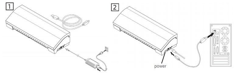 Fig.31 - Connection
 Once the machine is connected, we must remove the non-adhesive paper from the cutting mat and arrange it so that it enters the machine. We have fine materials like vinyl, medium weight materials such as paper and cardboard.
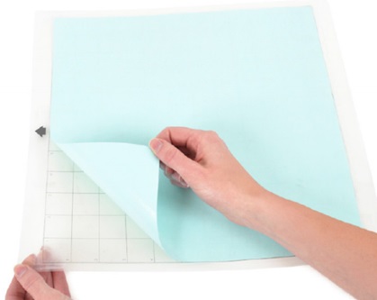 Fig.32 - Cutting mat
 If the template is worn or you want to ensure that the vinyl or other material such as cardboards, corks, etc. do not move in the template, you could use an adhesive spray
I placed the template, press the option to load on the screen of the cutter and secured it with an element similar to a handle
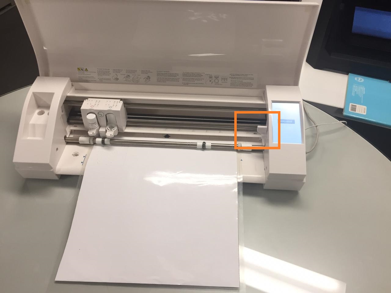 Fig.34 - Place of vinyl
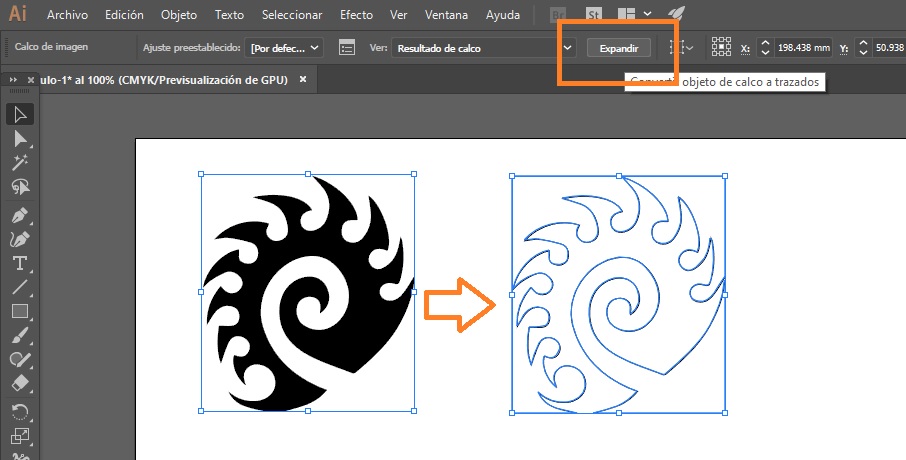
 Download the Logo of a video game and vectorized with the expand tool of the illustrator program. Later it was saved in the extension .dxf to open it in the software of the Cameo.
 Download Vinil Logo (.dxf)
 Fig.35 - Image to Vector
The program interface allows you to add some internal changes such as lines, enclosures and text. We must insert the file and click on the "send" option to proceed to change the parameters.
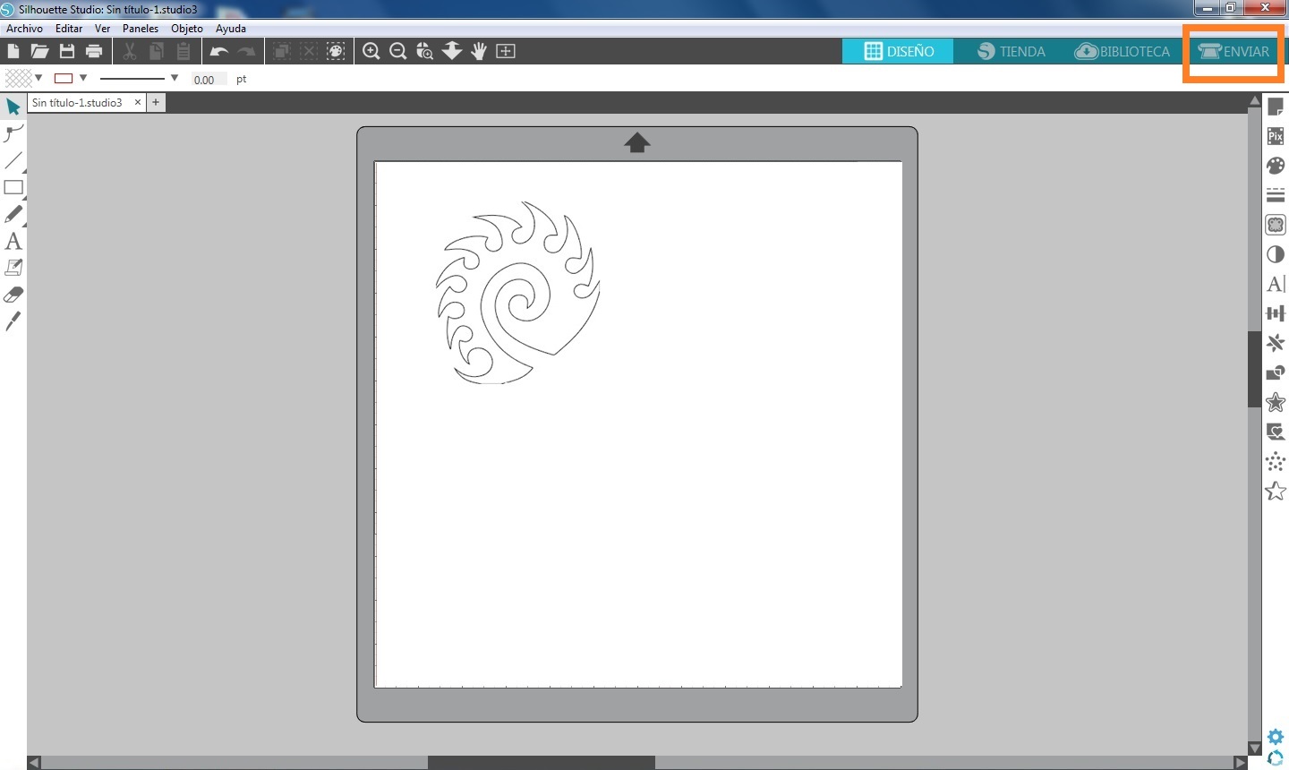 Fig.36 - Interface Silhouette
 To achieve the goal of cutting a silhouette, it is necessary to work with a vectorized image.
In the window, I inserted the vectorized image and I was able to configure the image size, orientation and cutting speed.
The parameters are the following: depth 1, speed 6, pressure 1 and passes 1. However the software of the silhoutte has some extra parameters such as material selection, the action of the machine and the type of tool that will be used.
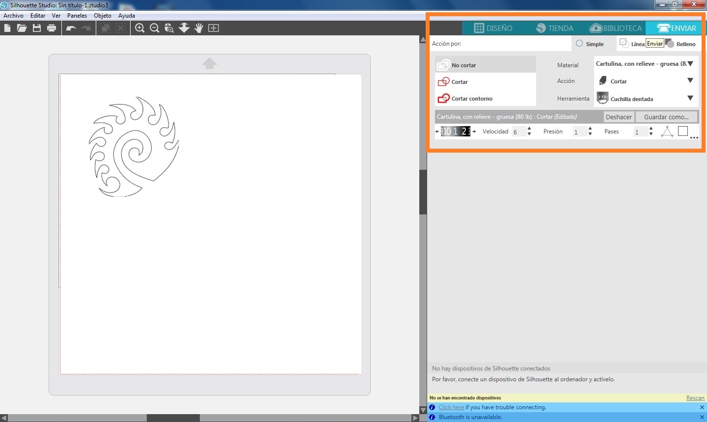 Fig.37 - Parameters
 The first movement of the machine is a vertical test of the blade, this way it is ready to cut.
This is how you cut the Cameo vinyl cutter
As you can see the pattern of curves was done perfectly, to remove the cut vinyl is enough to make pressure and bend the vinyl to allow us to hold a corner.
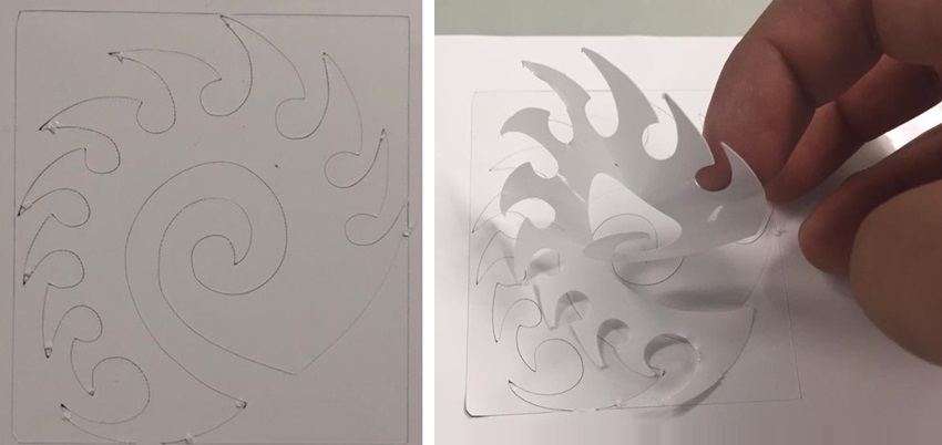 Fig.40 - Cut
 This is the final result of the vinyl cut
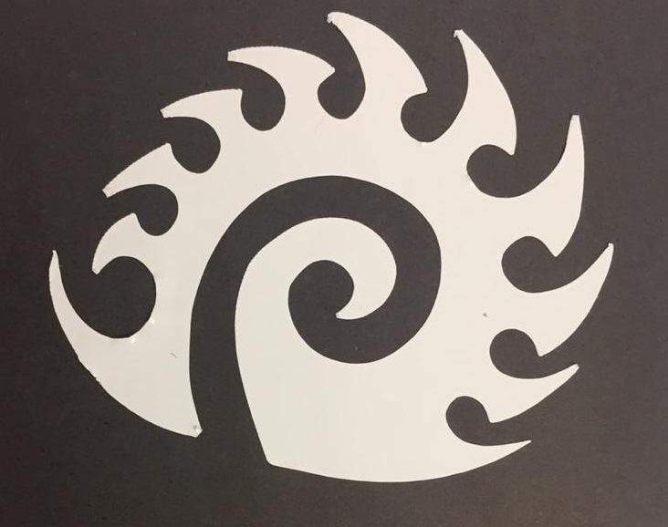 Fig.41 - Example
 Group assignment
In the group work, we decided to test the laser cutter making engravings to various types of stones that we got in the university, in this way we test the parameters and how well it records in this material. The picture shows all the stones that we used.
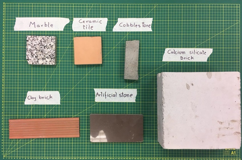 Fig.42 - Stone Example
 We tested the cobblestone as the first material, it was rasterized with a speed of 15% and a power of 100%. Being a material with a hardness superior to brick we can see that a clean finish is not achieved. The parameters are the following Speed: 40%, Power: 100%, Frequency: 50%
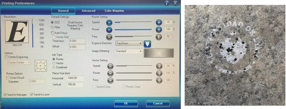 Fig.43 - Cobblestone
 The second material to be rasterized was an artificial stone, in the image we can see that there was no need to increase speed or power. The parameters are the following: Speed: 15%, Power: 100%, Frequency: 50%
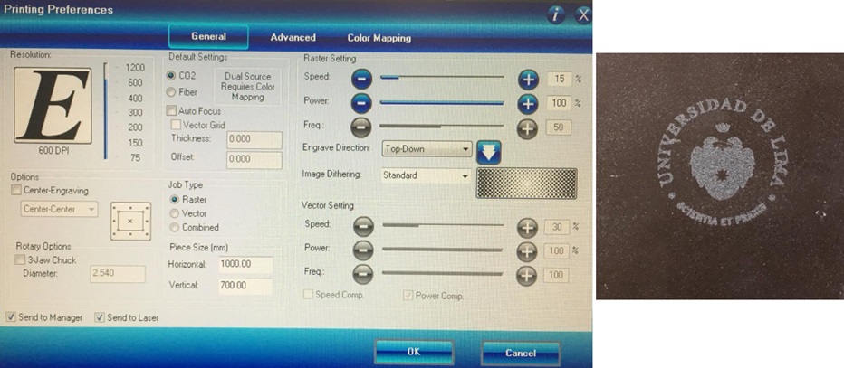 Fig.44 - Artificial Stone
 For our third test, in the claybrick, speed was taken into consideration since having granulated components, they are detached from the material. In this way, we realized the color of the engraving was controlled by increasing and decreasing the speed of the machine. We wanted to have an intense engraving so we used a speed of 10%. The parameters are the following: Speed: 10%, Power: 100%, Frequency: 50%
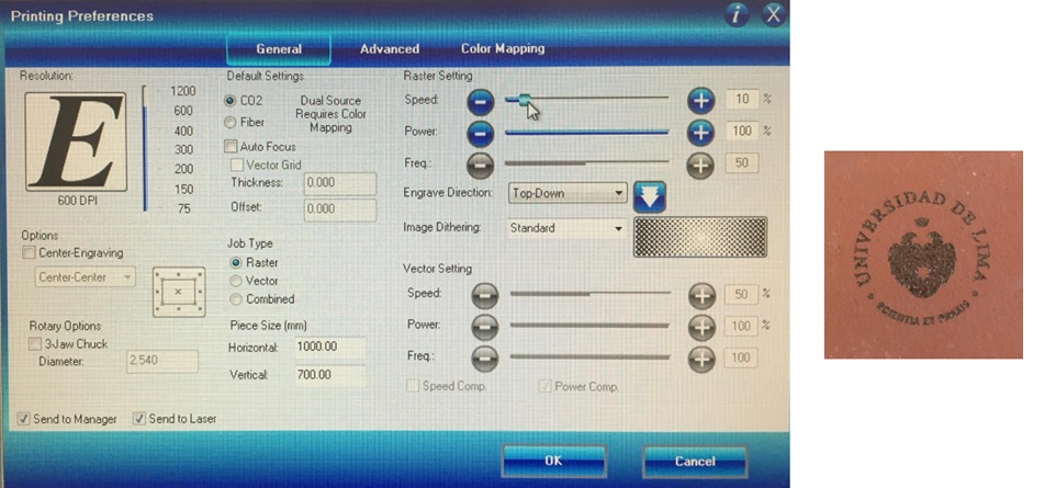 Fig.45 - Clay brick
 The ceramic has a varnished surface, which is why we increase the speed of rasterized so as not to burn the surface, we wanted to preserve the natural color of the material. The parameters are the following: Speed: 45%, Power: 100%, Frequency: 50%
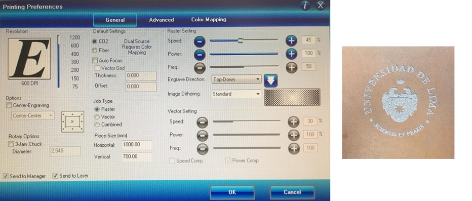 Fig.46 - Ceramic printing preferences
 Finally, we chose a material of great hardness, however much it decreased or increased the speed, a good finish was not achieved.
In this way, it is concluded that not everything depends on the parameters of the machine, but also that it is suggested to identify the properties of the material to be used. The parameters are the following: Speed: 40%, Power: 100%, Frequency: 50%
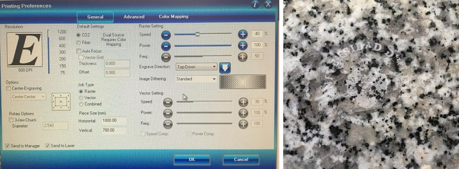 Fig.47 - Marmol printing preferences
 The next test was the creation of "combs" to verify the cut tolerance and the adjustment between them. It will observe measurements from 2.5mm to 3.75. This test has allowed us to generate perfect joints between materials such as MDF, cardboard and plywood.
To achieve the cut we used a speed of 3%, frequency of 100% and power of 100%
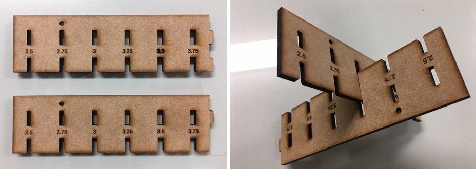 Fig.48 - Combs
 Download Combs dxf Files
To see all the documentation of the group work, you can visit the fourth week of the CIT page.