Week 5: Electronics Production
2019.02.13
Individual Assignments:
- Make an in-circuit programmer by milling the PCB. Complete
- Check it can be programmed. Complete
- Optionally, try other PCB processes. Incomplete
Group Assignments:
- Characterize the design rules for your PCB production process. Incomplete
Week 5 Contents:
- What I learned this week:
Milling with the MDX-50
Creating a programmer
The goal this week is to create a FabISP in-system programmer. Plugging this in between a PC and a freshly minted board allows you to program the microcontroller. This is only required once, then the new board can be plugged in directly and programmed with Arduino IDE.
Setting up the Toolpath
I opened the Hello.ISP traces PNG in Adobe Illustrator and converted the PNG to a vector using the Image Trace tool. This was so I can tweak the traces and move items around.
For version two I added my own logo using Adobe Illustrator.
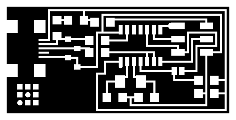
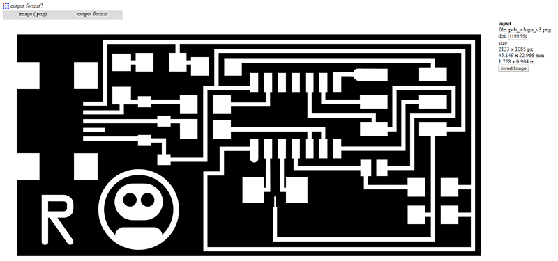
For version three I have changed the traces to allow fitment of a 20Mhz resonator as the timing device, rather than the crystals on the original. I have added an 'R' for Robotik and tidied up some of the traces that didn't cut very well due to the computed thickness of the gap between them. The tool could not fit, so Fab Modules did not make a toolpath for that section.
Here is the traces image for the PCB:
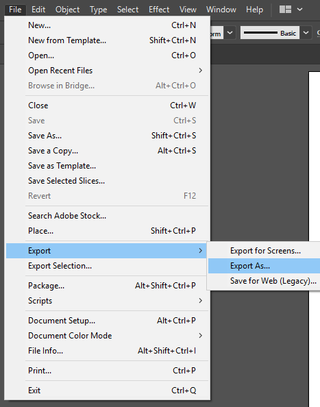
After preparing the files in Illustrator, I clicked 'File' > 'Export' > 'Export As' and chose .png format. I set the resolution very high, above 1000 dpi to make sure it was good qaulity when imported into Fab Modules.
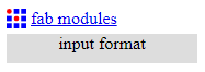
Next I went to fabmodules.org (I am aware this is the 'old fashioned' way of doing things now. A second process using mods.cba.mit.edu follows). When fabmodules.org opens we are presented with the following screen.
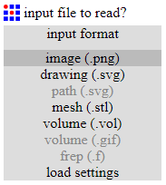
Click the grey [Input Format] button to choose an input format.
Select .png format from the dropdown.
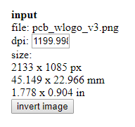
Select the correct file and click 'OK'. The file chosen will then load in the work area of the Fab Modules page.
Here you can invert the image if required (white parts stay, with the tool running around the outside of the white shapes). This group of settings appears on the right hand side of the screen - it is worth checking that the displayed measurements match what you are expecting.
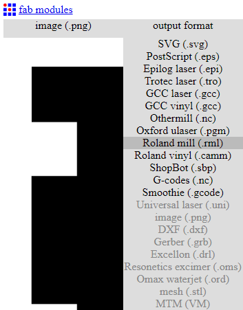
Click on the [Output format] button and choose .rml (Roland mill).
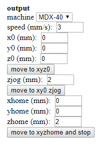
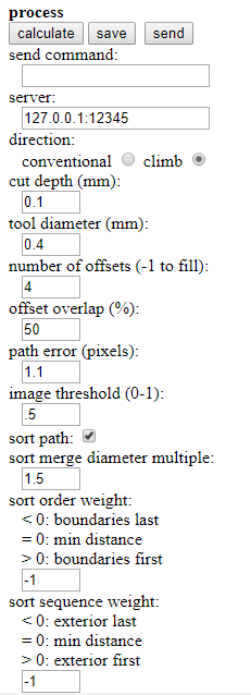
Once selected, the output fields will appear under the size measurements. In the image below these are filled in with the basic settings, to get them I first chose 'MDX-40' from the dropdown menu. This is the closest model to the MDX-50 in the lab. I then manually entered 0 for all except the speed, the zjob and the zhome. The 'zjog' setting here is important, this is the amount the tool will rise above the z origin when traversing the workpiece to a new cutting point. The 3 mm/s speed is the amount that the tool head will move per second, measured in millimeters.
The next step is to select the type of milling operation, using the 'process' button. The first option is for milling the traces. Our mill has a 0.4mm square end mill for this purpose, currently loaded in the 'Tool 2' slot.
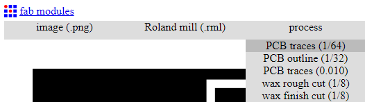
The process fields will appear underneath the output fields once 'PCB Traces 1/64' is selected. The fields are automatically filled (based on the MDX-40 selection above, I think).
Once the settings look right, press the [Calculate] button to generate the toolpath. Sometimes it can look like nothing is happening, but the tool is working away and the toolpaths will appear in due course.
The blue paths are the cuts and the red paths are the traversals at the height specified above.
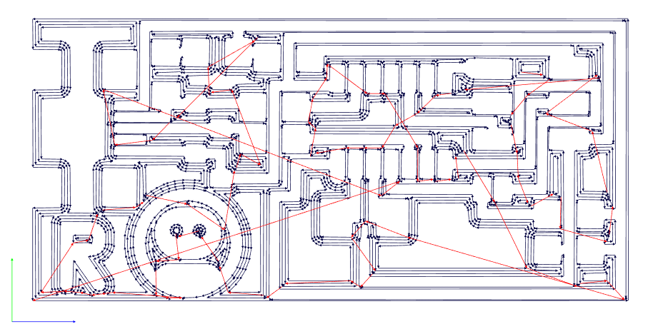
Once the toolpath appeared I clicked on 'save' to download the .rml file.
The file appears in the download folder when using Chrome on the PC attached to the mill. I cut and pasted this file to my own storage area.

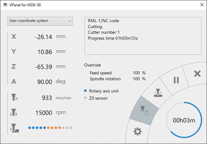
The software we use to send the job to the mill is the 'vpanel' software that came packaged with the machine. The 'cut' icon shows a tool milling a panel and shrapnel flying out. Click this to open the file dialogue. Click 'delete all' to remove any past jobs. Click 'add' and locate the .rml file.
The mill will start as soon as the 'output' button is clicked, so before we do that we need to set up the hardware.
Downloads
Traces
RML toolpaths from fabmodules
Hardware Setup
Setting up the MDX-50 for PCB Milling
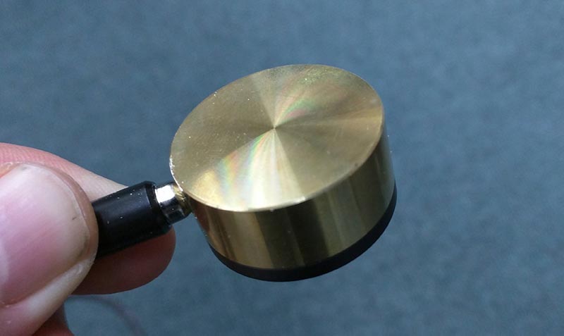
This is the brass auto Z tool. To automatically set the Z height this tool is placed on top of the workpiece and the tool head is positioned above it (by rotating the dial through the x and y axes), you then move the tool down through the Z axis until it is relatively close to the brass cyclinder (~3cm) to negate having to watch it move very slowly when running automatically. The tool tip will move down automatically until it touches the top of the brass cylinder - a low voltage is passed through the brass cyclinder and as the tool touches the top of the cylinder a circuit is completed, stopping the chuck immediately. The machine then calculates the Z origin based on the height of the cylinder and zeros it to the top of the workpiece.
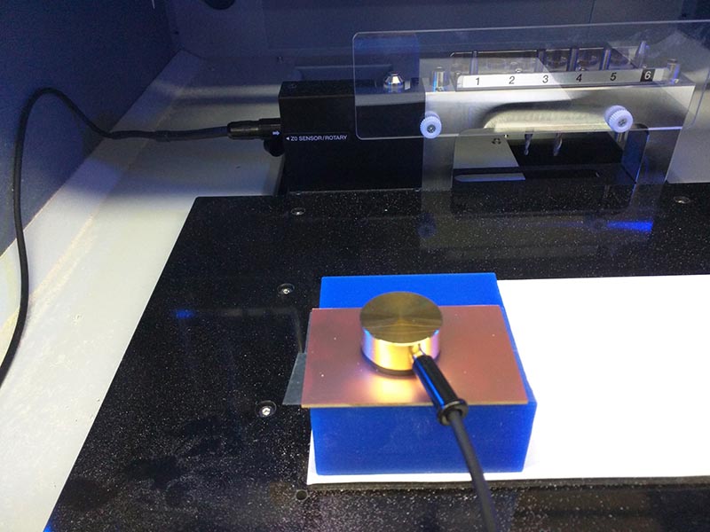
This is the auto Z tool in place on the workpiece. The wax block is the sacrificial and the copper board is destined to be a PCB. The cable running from the tool to the tool stand allows the machine to detect when it touches the brass.
Milling and soldering
Making the board
The video below shows the MDX-50 at work. The sacrificial wax block below the copper was surfaced to make it flat.
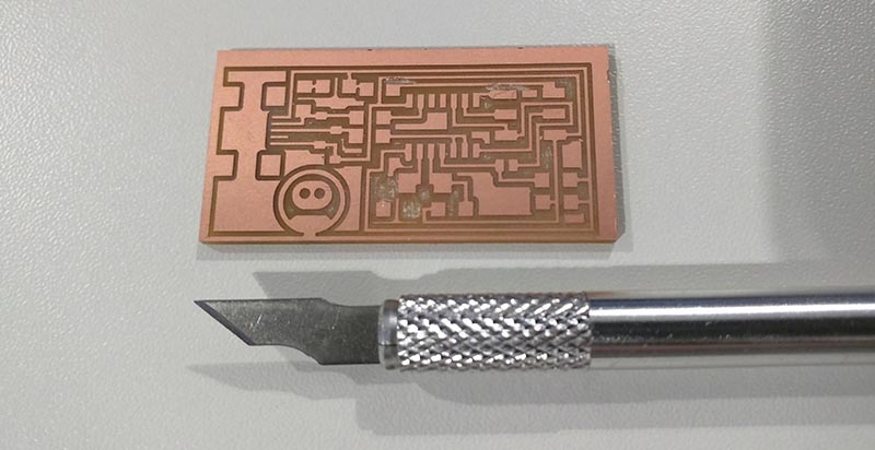
Here's the milled board, just before cleaning. This is a photo of the first attempt at the board. The one shown later in the final image is slightly different.
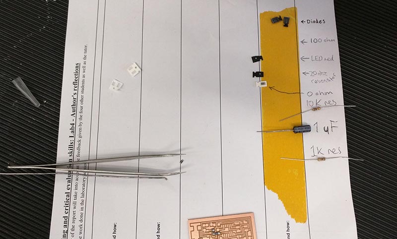
While soldering the parts it was useful to use a piece of double-sided tape to keep the small surface mount parts neat and tidy while working.
I have soldered a couple of times before, but only to repair things or make very basic kits. Here's my first attempt at soldering the board.
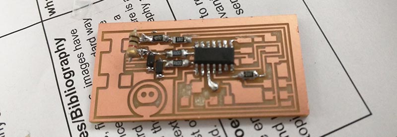
I ended up burning the board when soldering and desoldered the parts. I milled another board, this time removing all the copper between the traces and fixing the crystal. I then soldered this board. Some of the joints are 'smooth & shiny' and some, well, some are not!
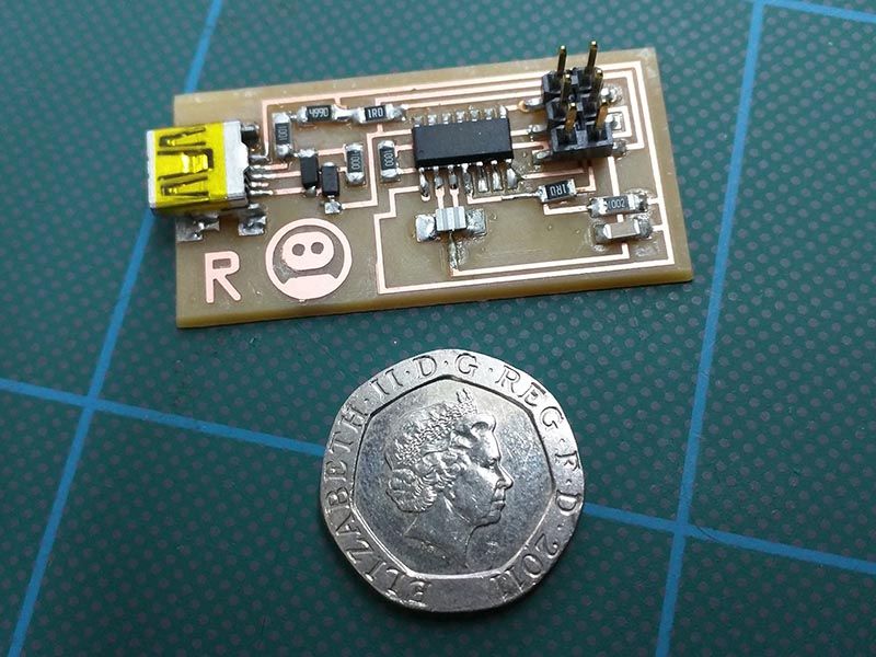
Here is the final PCB next to a 20p coin for size comparison:
After soldering the board I tested all the joints and traces with a multimeter in continuity mode. The board caused beeps in all the right places!
Programming the board
Using another programmer
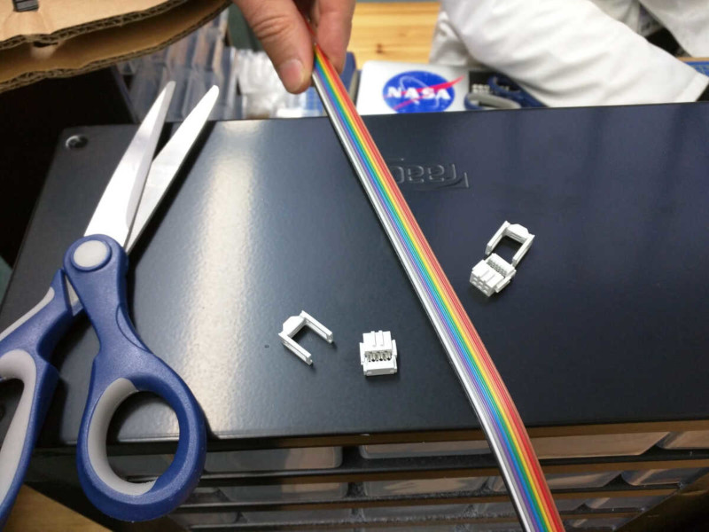
The next task was to program the board. I made a ribbon cable with 6 cores to connect the ISP headers from this programmer to the lab programmer.
I then followed this tutorial.
I'm using a Linux laptop and another programmer of the same type that was made by Luiz, our instructor. My Linux distro already had AVRdude and GCC installed, so I skipped those parts of the tutorial.
The tutorial suggests using the following command to fetch the firmware, but I couldn't get it to work. I used the Mac firmware link instead.
$ wget http://academy.cba.mit.edu/classes/embedded_programming/firmware.zip
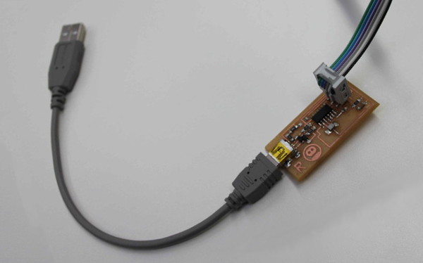
I connected the working programmer and my raw programmer board to my laptop via USB and then connected the two with the ribbon cable. As per the tutorial, I then edited the makefile using:
$ nano makefile
I switched out the AVRISP2 line for the USBTINY line by shifting the '#' comment marker to the other line, commenting out the AVRISP2 line. Wrote out the makefile using [CTRL]+[O} in nano, then used {CTRL}+{X] to exit. Next, on the command line, I gave the following commands:
$ make clean$ make hex$ make fuseThis was a very easy process for me and my programmer worked the first time I tried it (avrdude done. Thank you). This does not seem to be the case with other Fab Academics(?), so I think I have been very lucky. I checked the programmer by using the list usb command:
$ lsusb
This gives a list of all the USB devices connected, which now includes a line for my FABisp programmer:
Bus 002 Device 004: ID 1781:0c9f Multiple Vendors USBtiny
I desoldered the 0ohm resistor to the top left of the ATtiny44 chip in the image below (compare the image with the 20p above to see which resistor is removed) and my programmer is finished.
Measuring the Runout
Dial Test Indicator
The wonderful Adam, a technician that runs a much more accurate CNC machine at the University came down to the Fab Lab and shared some of his expertise with us. He brought three tools:
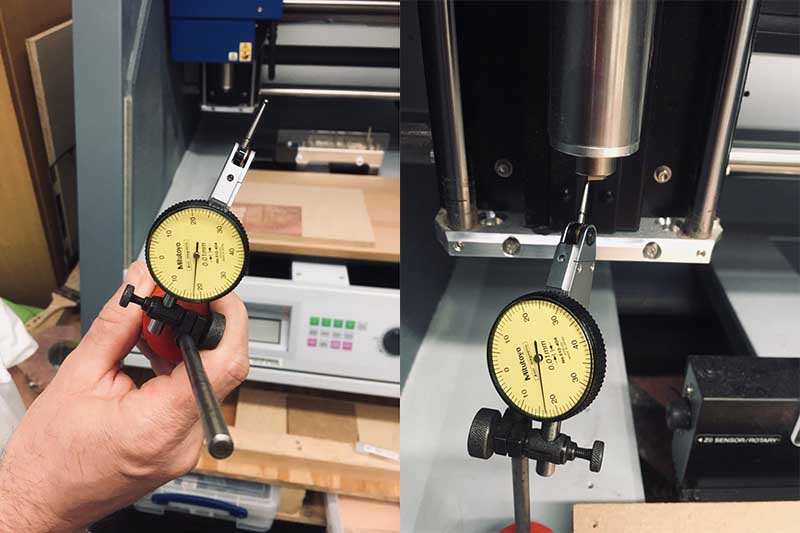
- A Dial Test Indicator
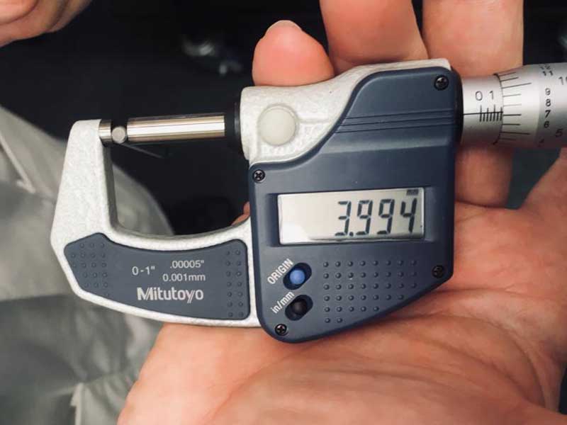
- A micrometer
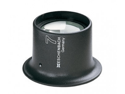
- An eyeglass
The micrometer is an accurate screw gauge measure, more accurate than the digital calipers we have in the lab.
The eyeglass is a lens mounted in a plastic ring - it magnified the tools to the point where we could see the wear on the flutes. Looking at the specs for the Eschenbach 11247 it provides 7x magnification with a 25mm lens and Eschenbach call it a watchmaker's loupe.
With no tool or collet mounted in the spindle Adam measured the error to +/- 0.18mm (180 microns) which seems a small amount to me, but did not impress Adam! He suggested that the tool may have been engineered to compensate for the single sided grub screw collet, so we mounted a tool in the collet and measured the runout with the DTI touching the outside of the tool.
The new measurement was +/- 0.06 (60 microns), so a third of the error measured with jsut the spindle. This is the total, if we were to express this to others it would be 30 micron runout or 0.03 mm. On a 0.2mm tool this is a significant amount of runout.
Adam's general advice was to run the spindle at the highest speed (for our MDX-50 that is 15000 rpm, which Adam considered slow) and to use single or double flute cutters at that speed. Slowing down the feed would also make cleaner cuts.
References
Online
- CNCCookbook: Be A Better CNC'er. (2018). G54, G52, & G92 G-Codes: Work Offsets & CNC Fixtures Made Easy. [online] Available at: https://www.cnccookbook.com/g54-g92-g52-work-offsets-cnc-g-code/ [Accessed 5 Nov. 2018].
- Oskay, W. (2018). Basics: Finding Pin 1 | Evil Mad Scientist Laboratories. [online] Evilmadscientist.com. Available at: https://www.evilmadscientist.com/2010/basics-finding-pin-1/ [Accessed 30 Mar. 2018].
Offline
- Nussey, J. (2013). Arduino for Dummies. John Wiley & Sons, Ltd., Chichester, West Sussex, UK, 2013.
Images
- PeplerOptics, (2019). Eschenbach Loupe [ONLINE]. Available at: Eschenbach Watchmaker Loupe (7x) [Accessed 17 February 2019].