Fabrication
One of the main objectives of the project was to make a DIY prototype, something fabable, that anyone could make in a digital fabrication environment. This was a real challenge, because historically the instruments are handmade and are very complicated to fabricate, but I was not trying to make a perfect instrument, but making a working and new instrument with electronics and new features. Those are the processes and machines I used.
3D printing
This is one of the most accessible and affordable digital fabrication process, almost anyone can have access to a 3D printer or to a specialized place with them, so for me it was a really interesting tech to use to make it more accessible. For this reason I decided to use it for the main structure. Please, find the design files and the design decisions in the Final Project Design Page.
Printers
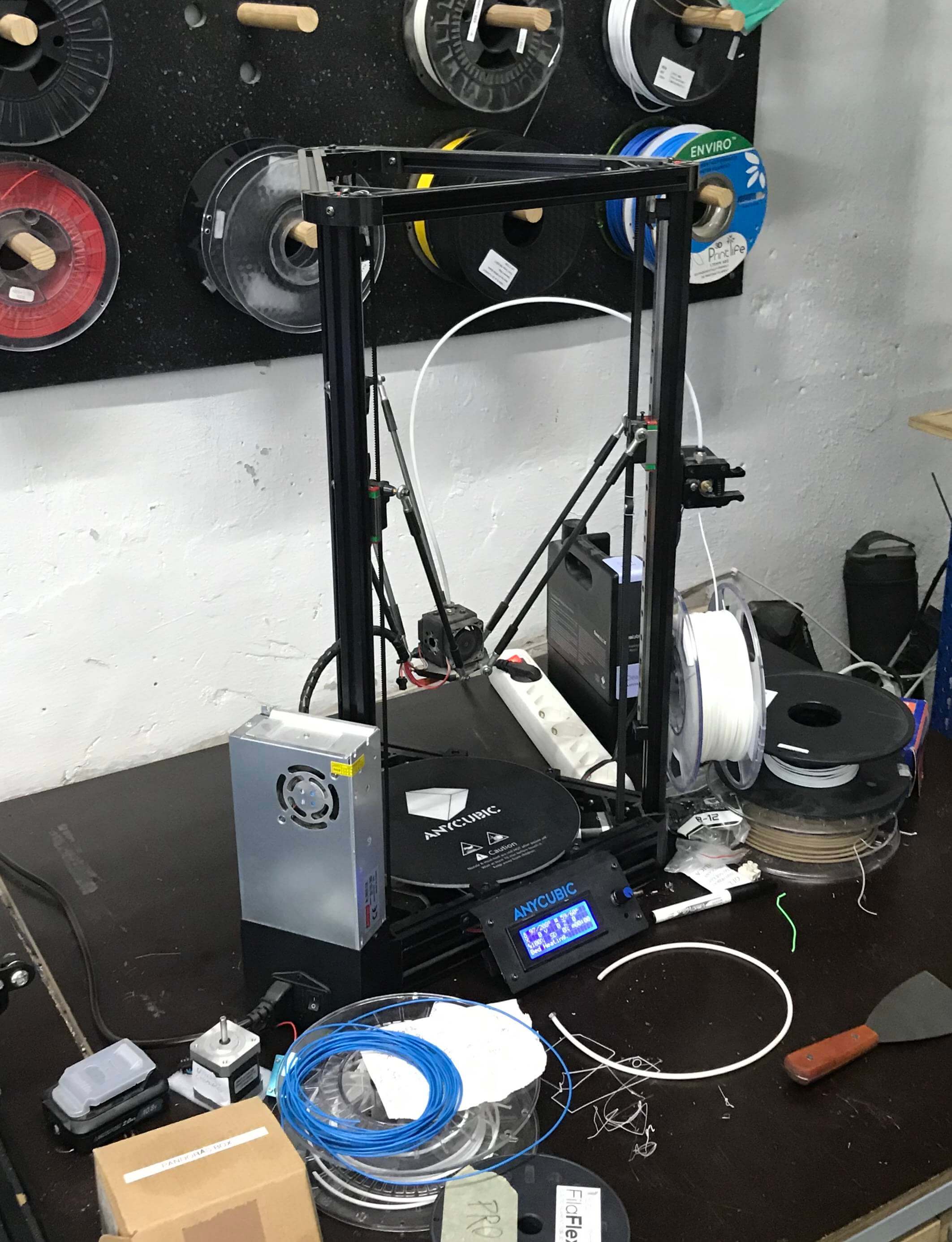
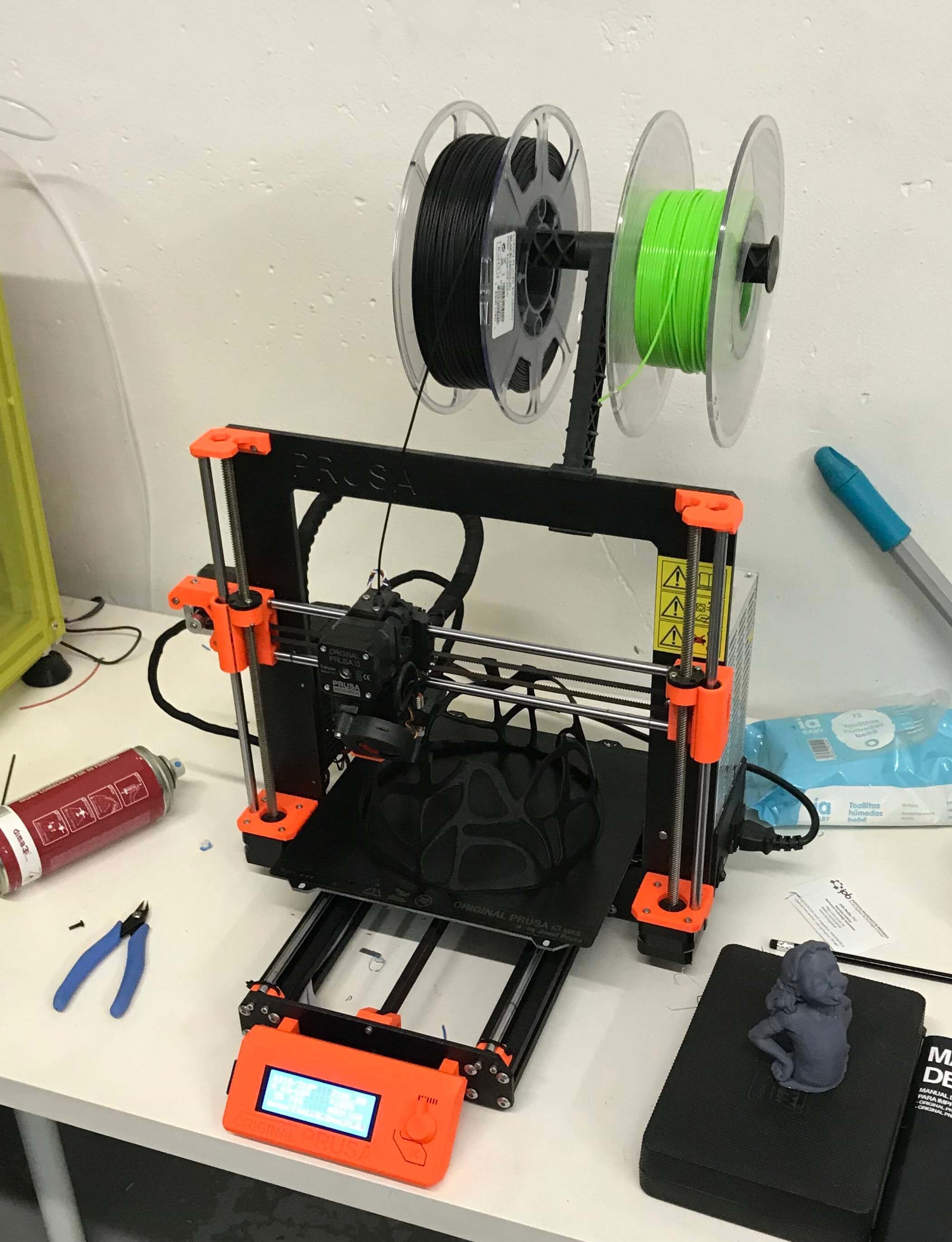
For printing this project I used 2 different printers, the Prusa mk2s i3 and the Anycubic Kossel Linear Plus. I decided to go for this 2 printers because they are available here at the lab and represent the main 3D printers, a Cartesian one, the Prusa, and a Delta bot, the Anycubic. The two printers gave and amazing result, and I used them to build all the parts of the main structure. The Anycubic was used for the higher parts like the neck and the Prusa was used for the bigger parts because it has a much bigger build plate.
Slicing Softwares
To slice the STL files I used 3 different slicing softwares. For the Anycubic printer I used Cura by Ultimaker and for the Prusa I used the Prusa Control software and the Slic3r Prusa Edition. The three softwares are presented in the documentation of Week 5, are OpenSource and easy to install and use. I used twi softwares for the Prusa printer because I decided to print the Frets in translucent PETG, and the Slic3er software gives more options to get the perfect settings. Those are the main settings I used for all the pieces:
- Quality: 0.2mm layer Height. A nice quality, as it was a big piece it was better to minimize the time operation.
- Infill: 20%. I needed pieces with strength to support the tension of the strings. After some tests, I found that this infill was perfect for the purpose.
- Supports: None or Only from Build plate. I only used support for the Head, because of the round holes. All the other files are prepared to be printed without supports.
Here it is the list of printed components and important information:
-
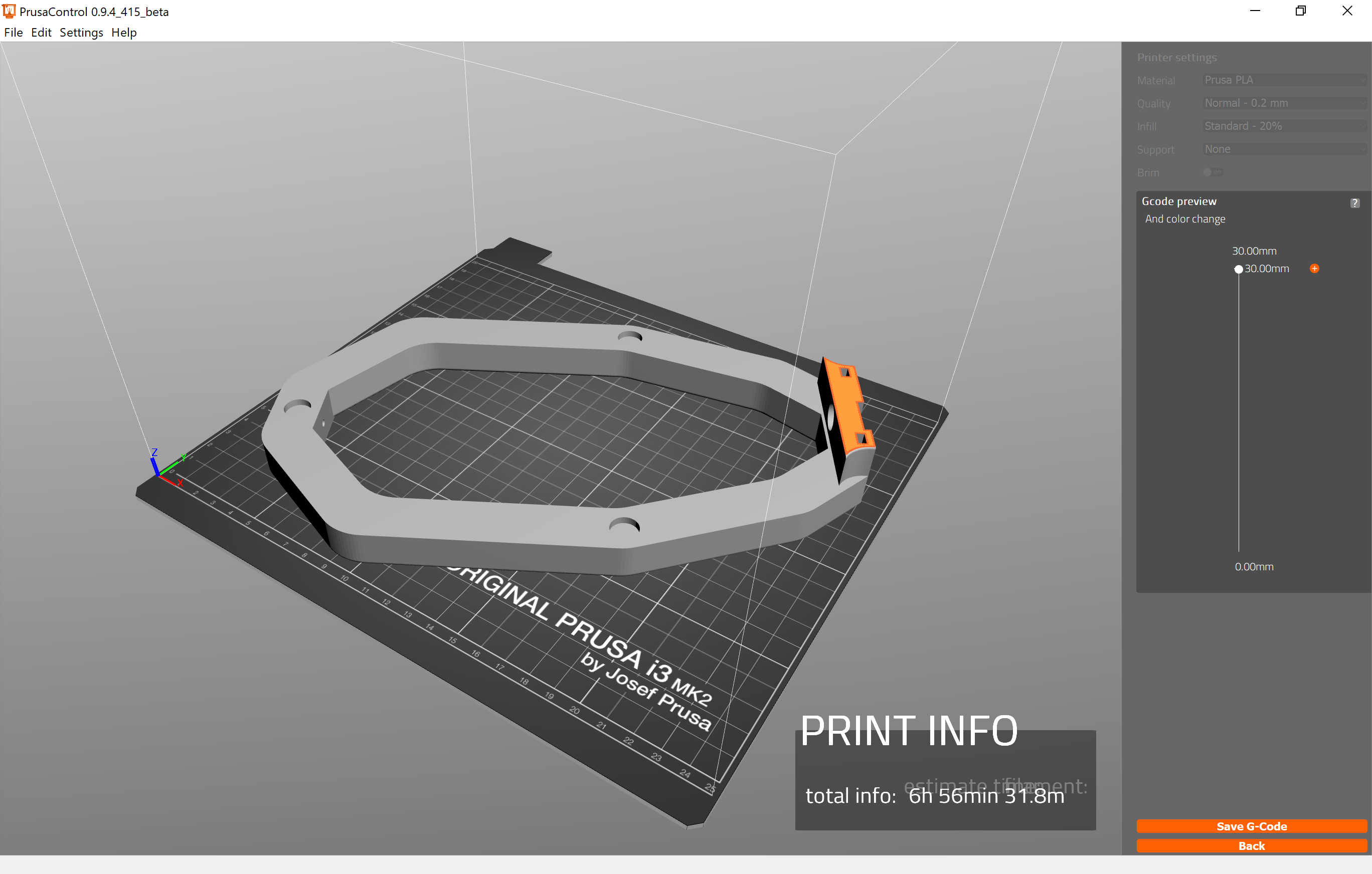
Body Join: This is the main part of the body. It was printed in the Prusa printer, using PLA and sliced in PrusaControl. The total print time is approximately 7 hours.
-
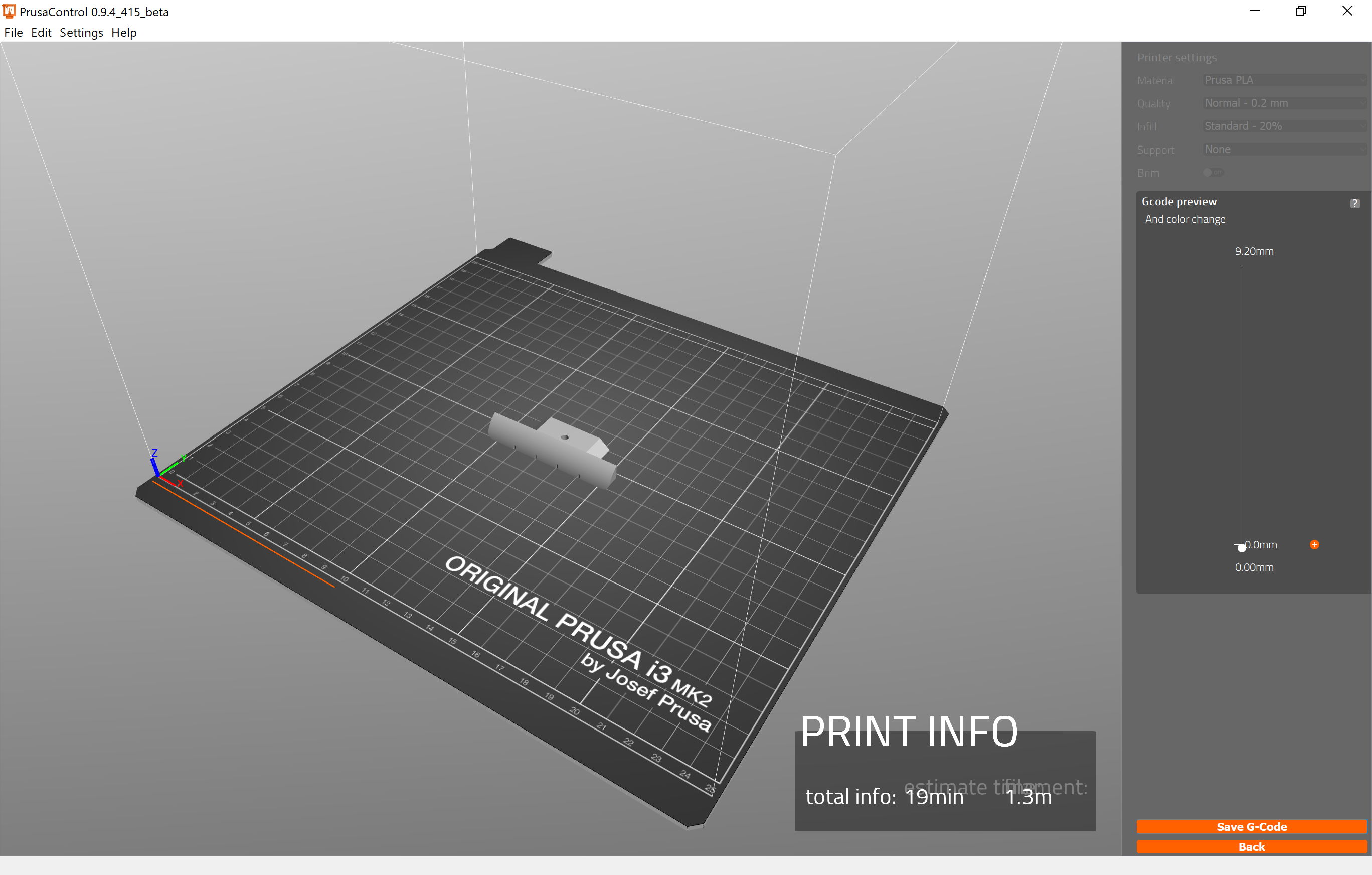
Bridge: It was printed in the Prusa printer, using PLA and sliced in PrusaControl. The total print time is approximately 20 minutes.
-
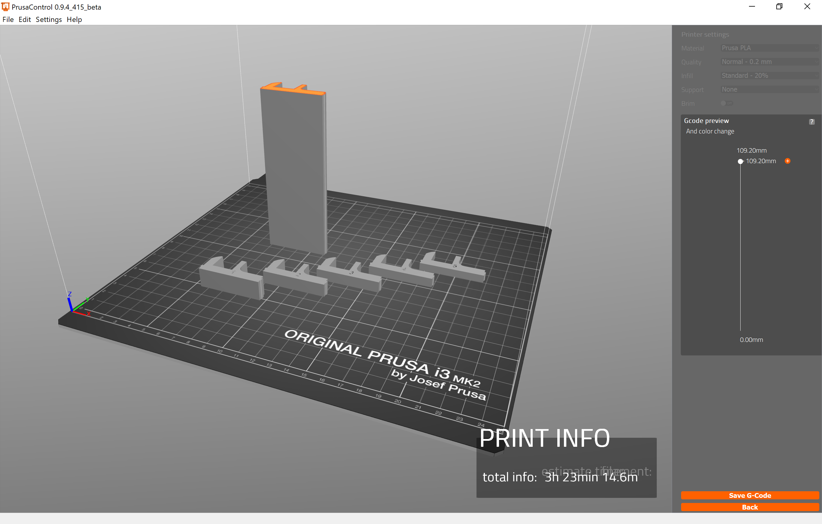
Interior Blocks: This block where designed to separate the different modules. It was printed in the Prusa printer, using PLA and sliced in PrusaControl. The total print time is approximately 3 and a half hours, but I recommend to print them separately.
-
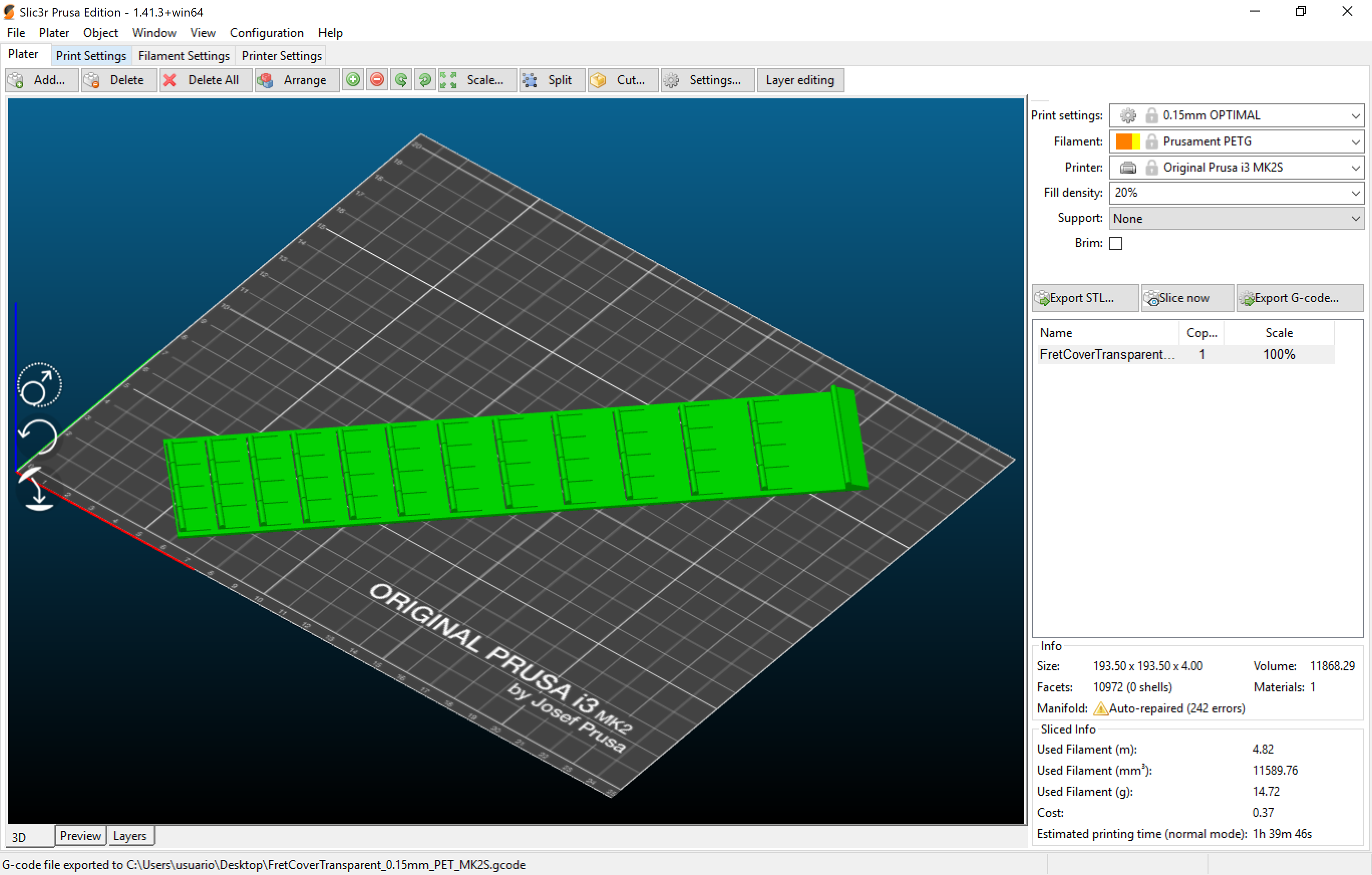
Frets: This is the only piece that is not PLA, it was printed with PETG, setting the temperatures to 235º the Nozzel and 80 the bed. It was sliced in Slic3r. The total print time is approximately 1 and a half hours.
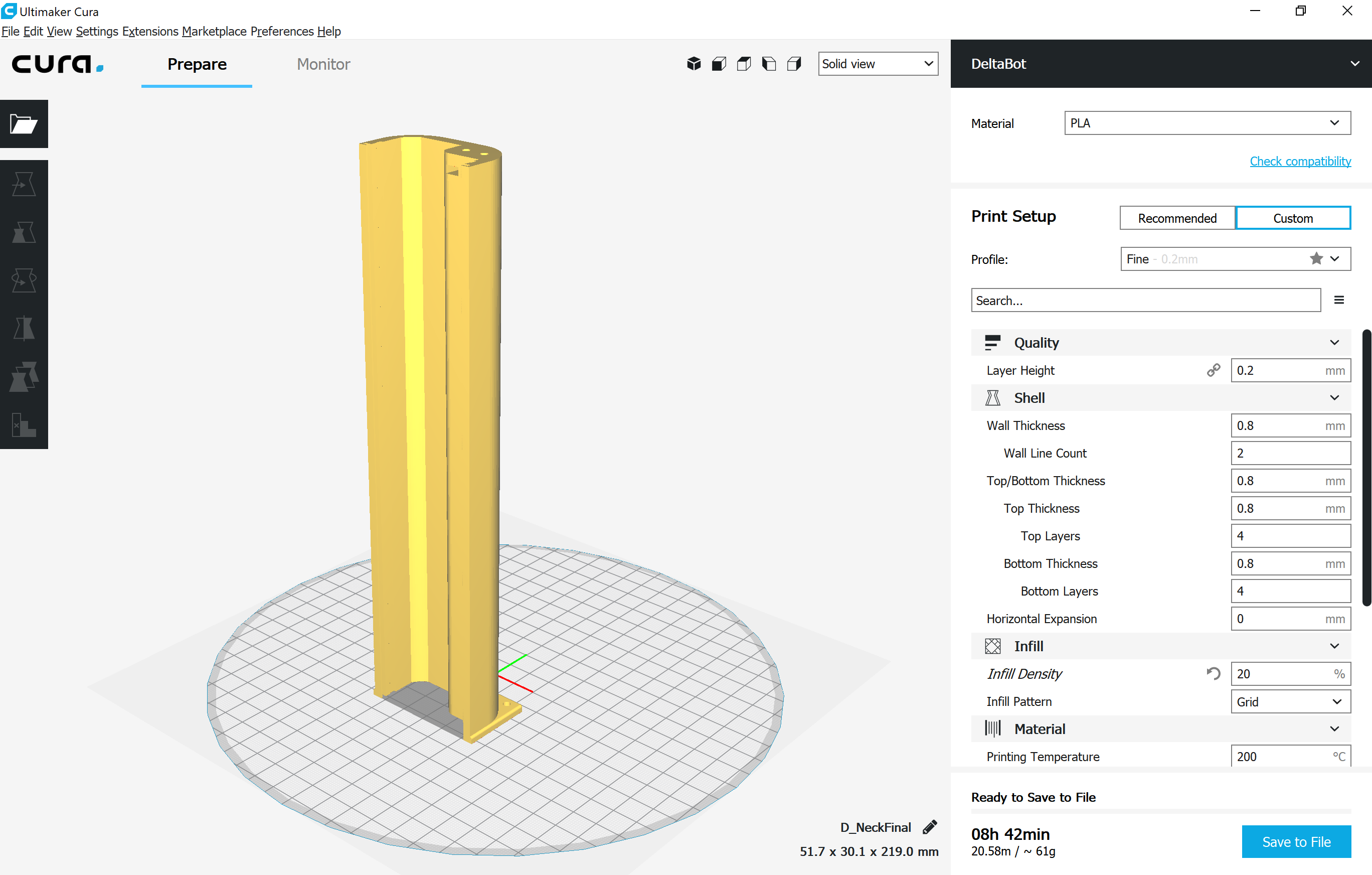
-
Neck: This is the longest part to print because it was printed along Z axis, and it is always longer than the XY plane. It was printed in the AnyCubic printer, using PLA and sliced in Cura. The total print time is approximately 9 hours.
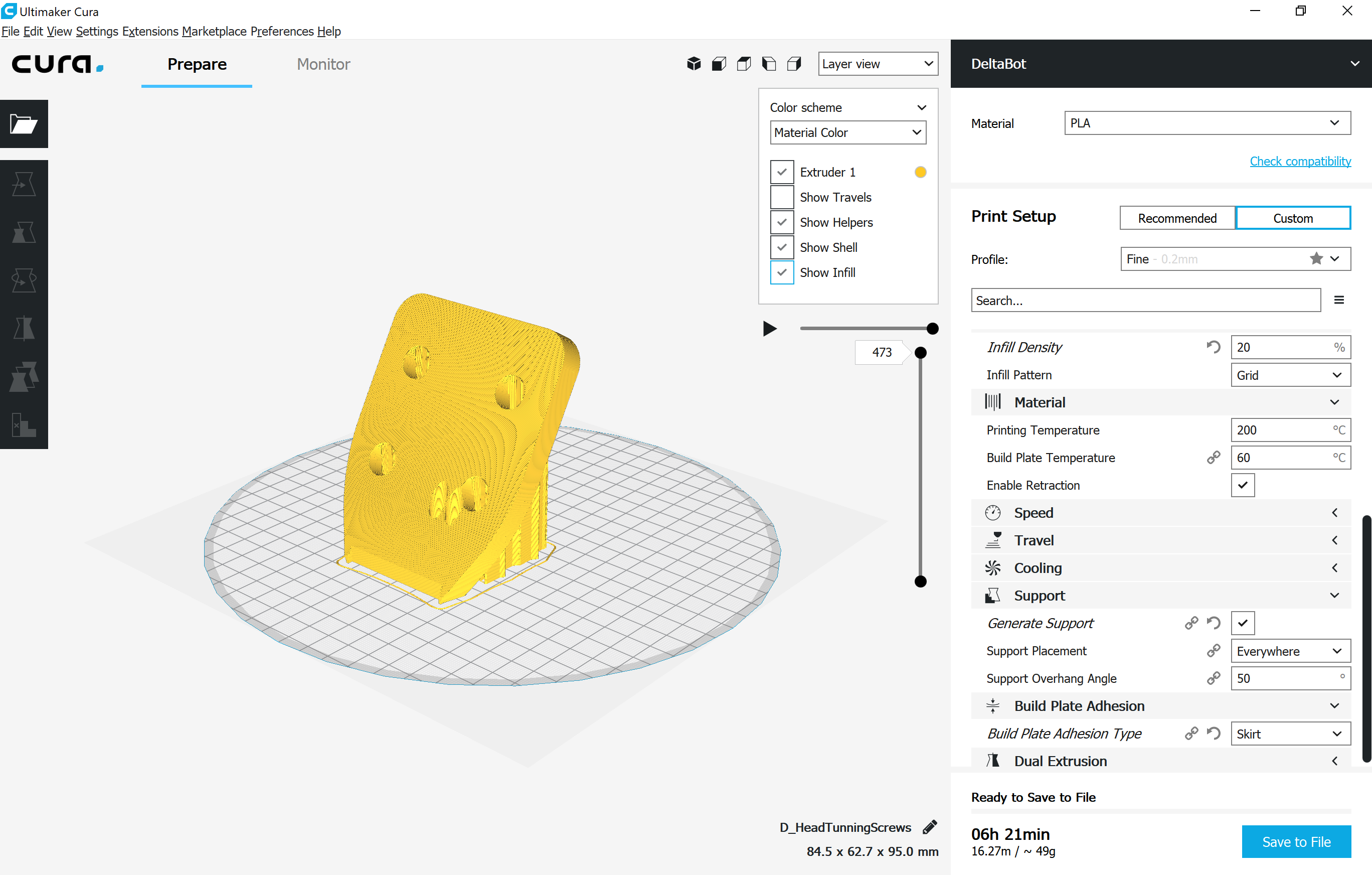
-
Head: Like the neck, it was printed along Z axis, so it takes some time to print. Also, note that this is the only piece printed with supports. It was printed in the AnyCubic printer, using PLA and sliced in Cura. The total print time is approximately 8 hours.
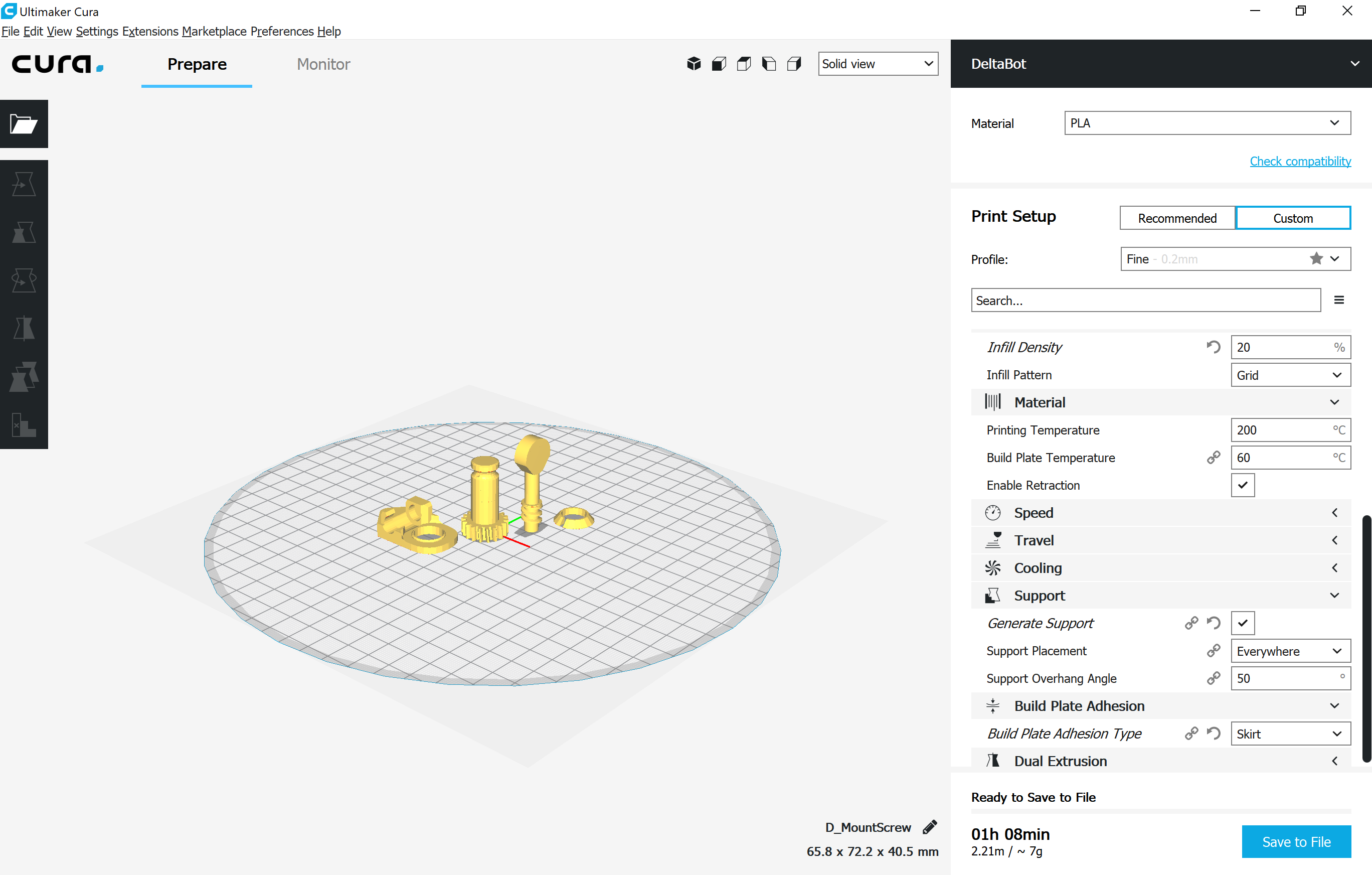
-
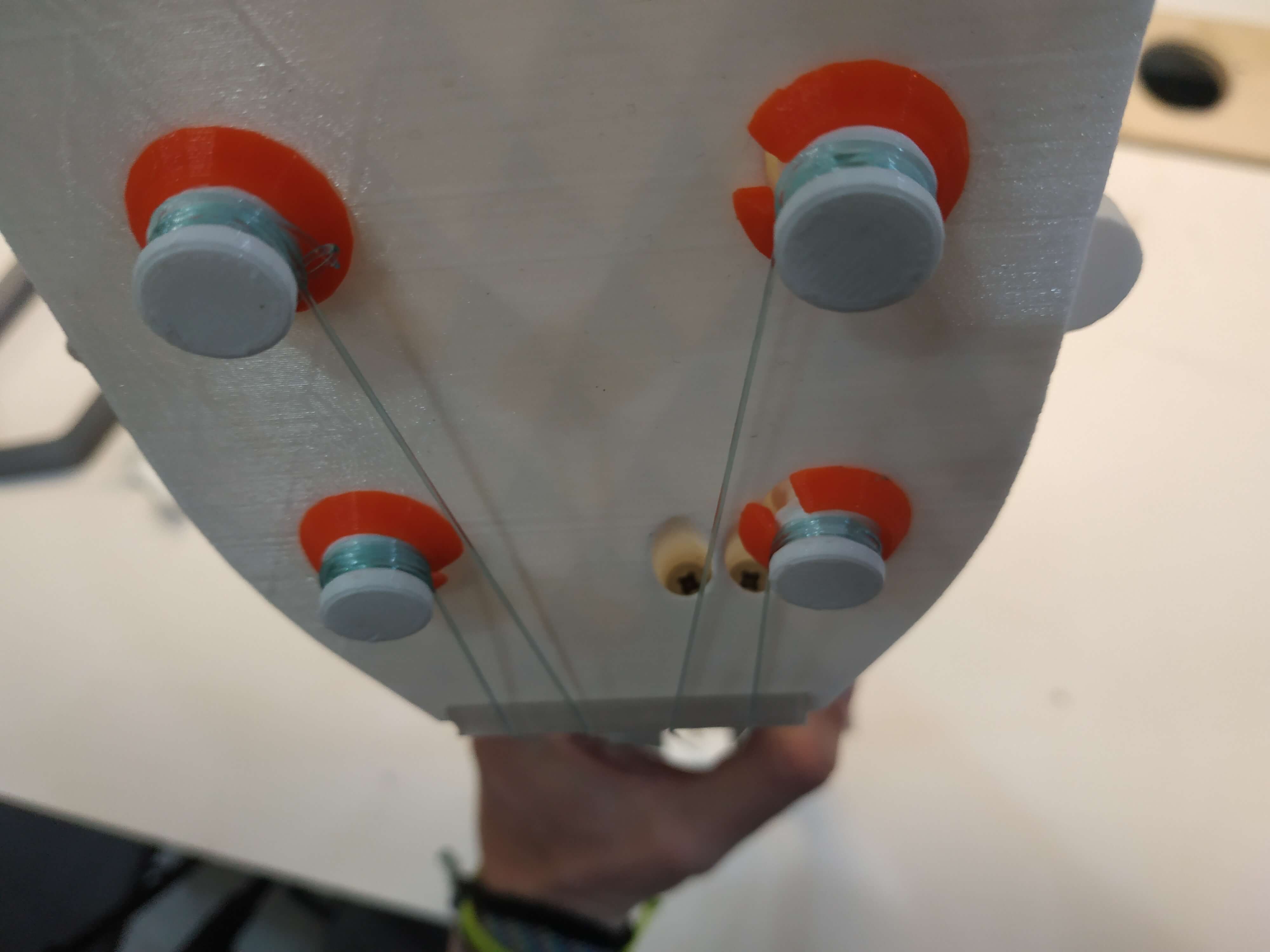
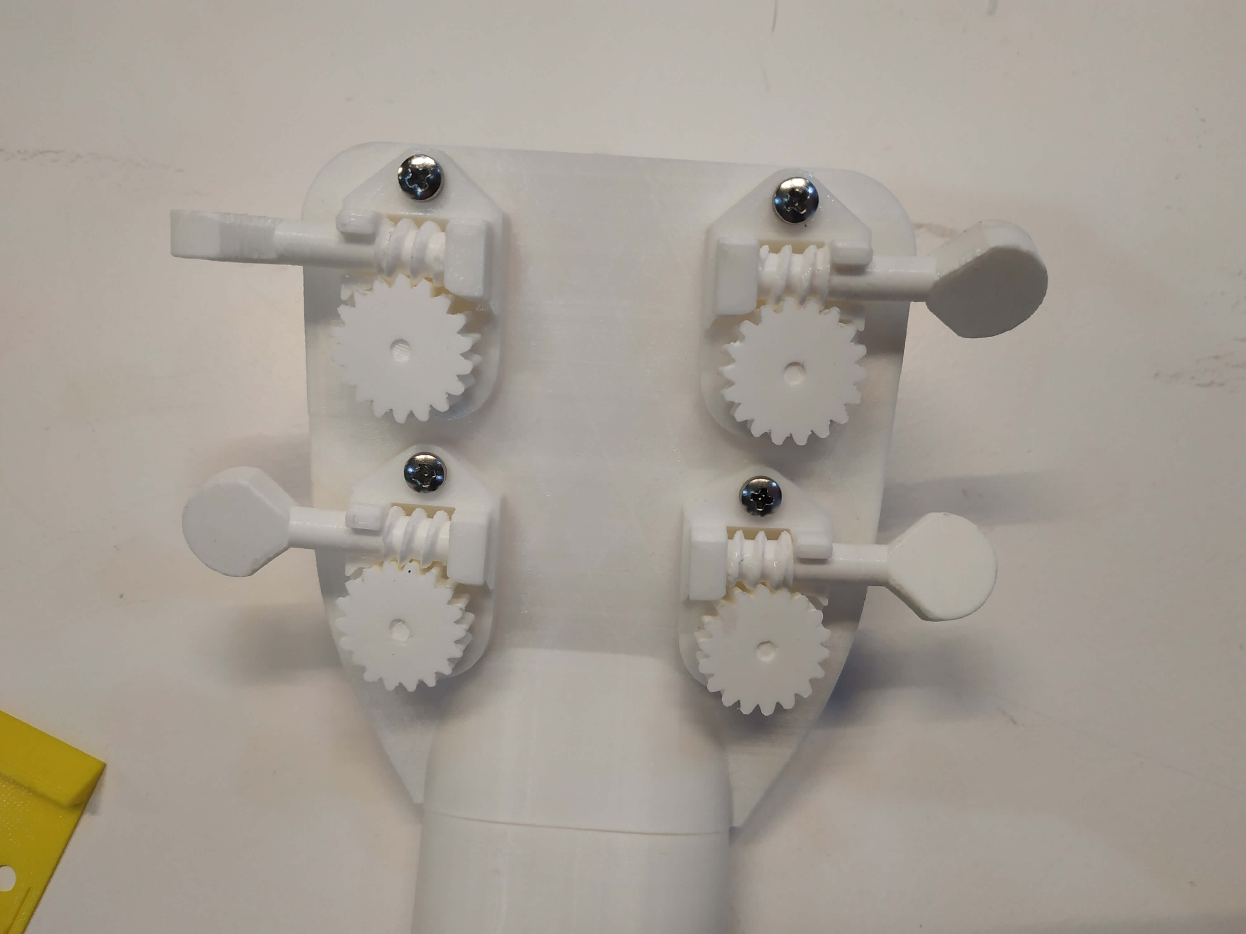
Tuning Pegs: I recommend printing the different pieces separately to make it faster and without errors. It was printed in the AnyCubic printer, using PLA and sliced in Cura. The total print time is approximately 1 hour.
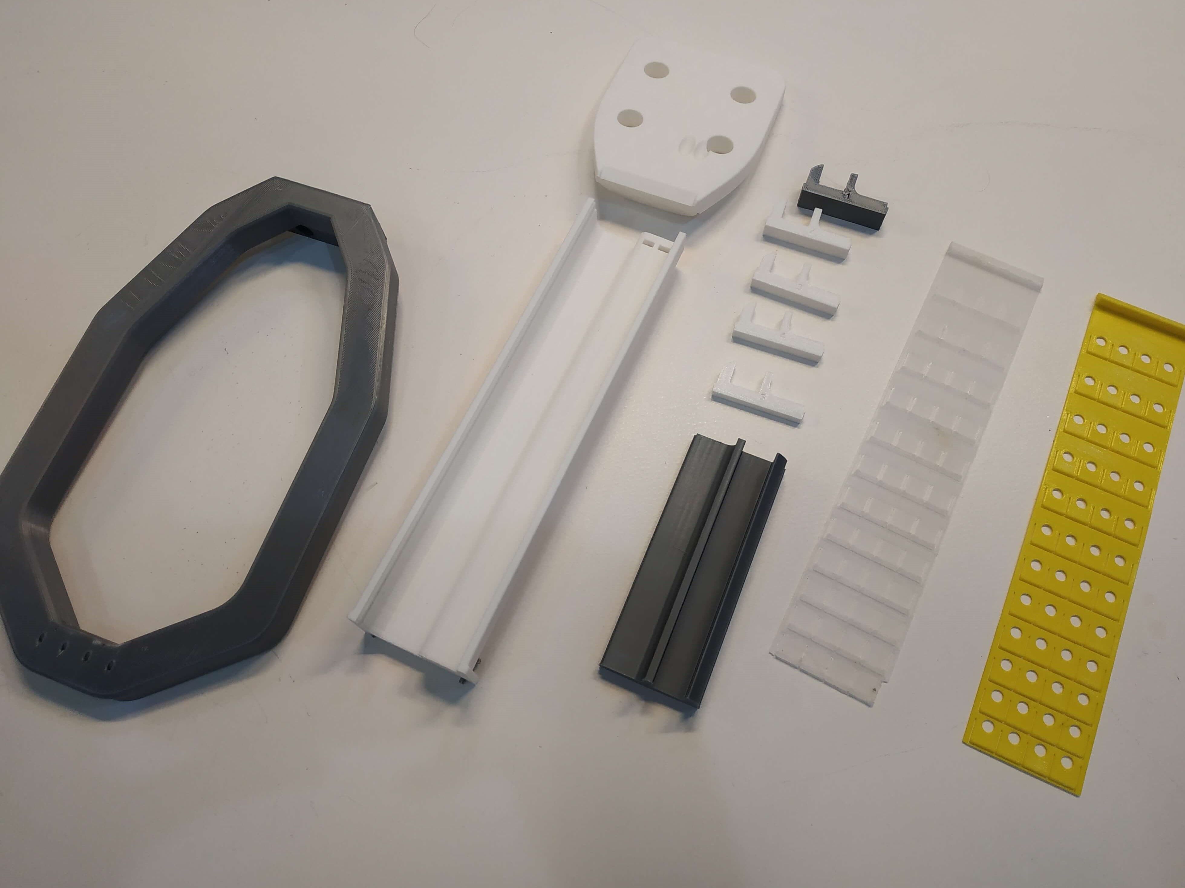
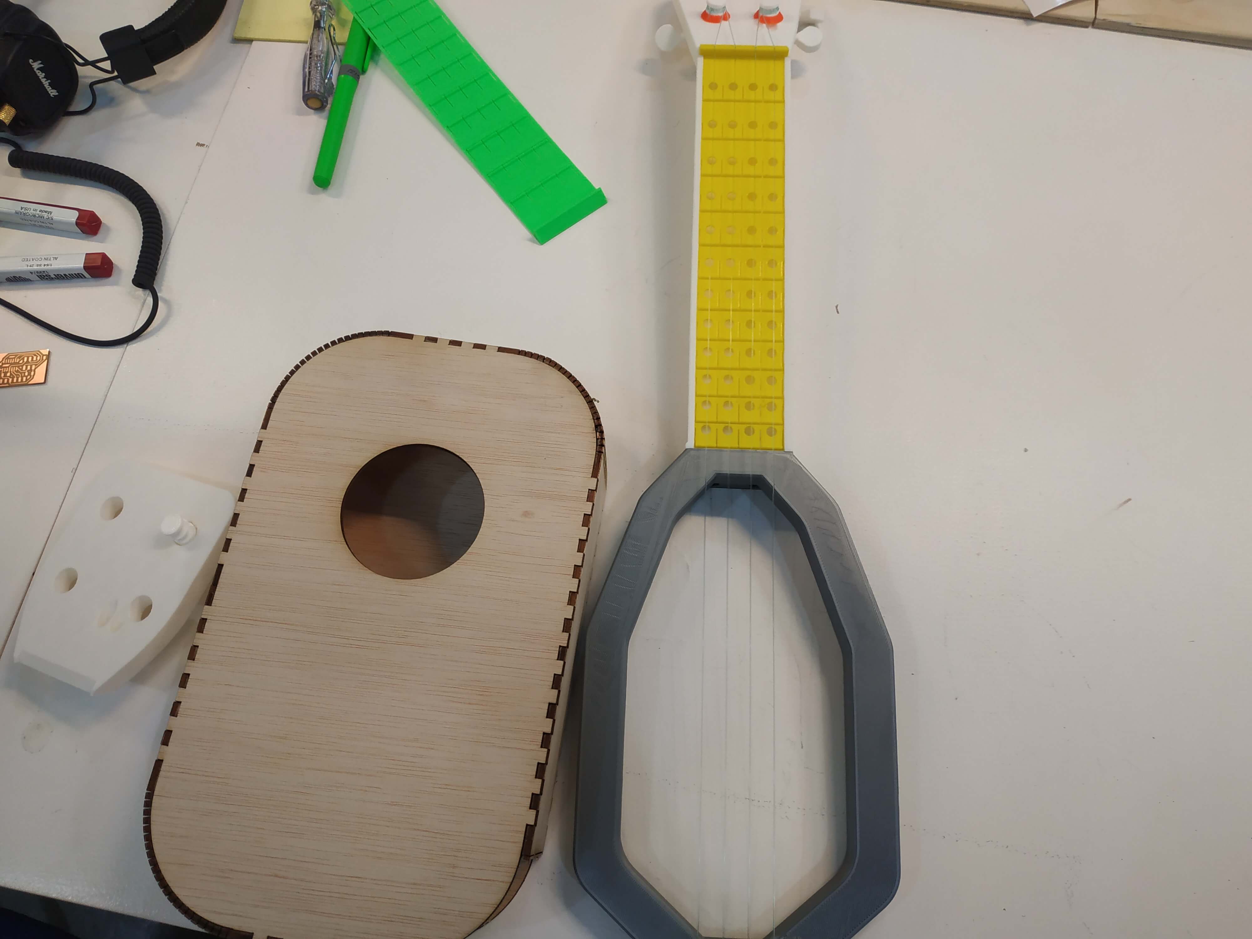
This is a photo of the main 3D printed parts:
Electronics production
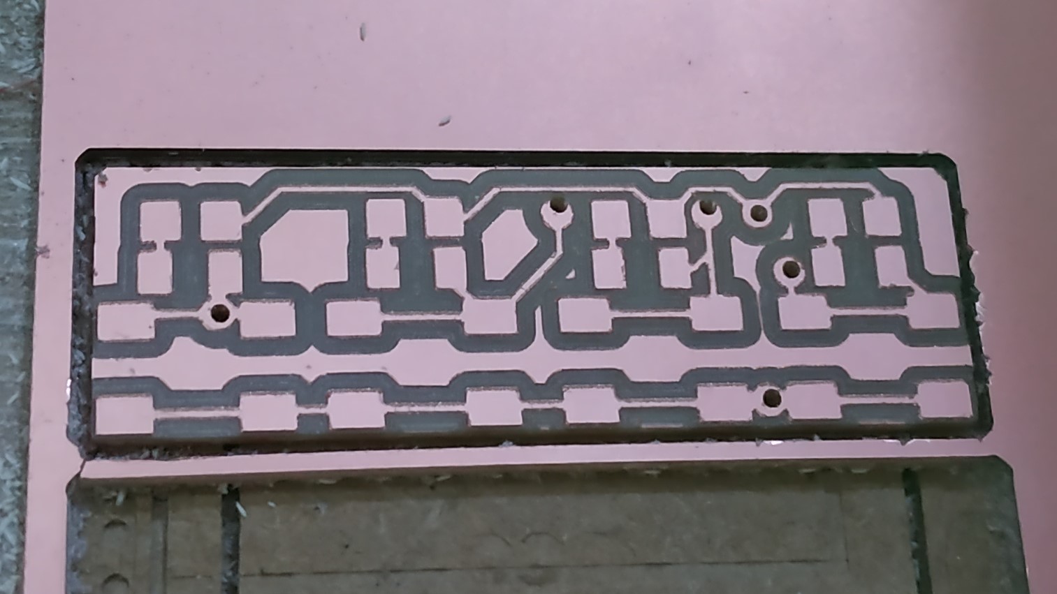
For the electronics production I used the Rolland SRM-20 mill. I followed the process described in Week 04 and Week 06. This is a subtractive fabrication process, and I used Mods to make the files for it.
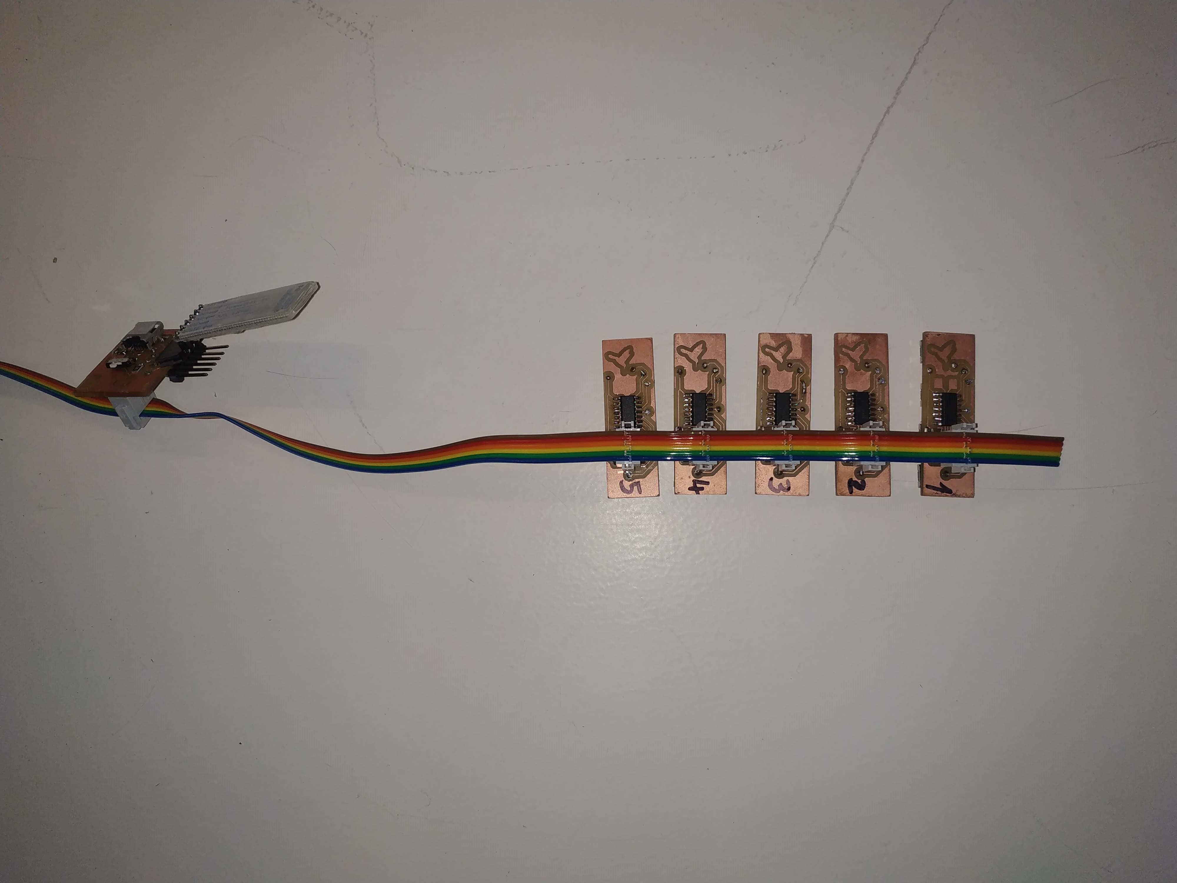
I used this technic a lot during FabAcademy and the Final Projects, as I needed 5 Fret boards and one master board for each Ukulele. Those are the settings I used in Mods:
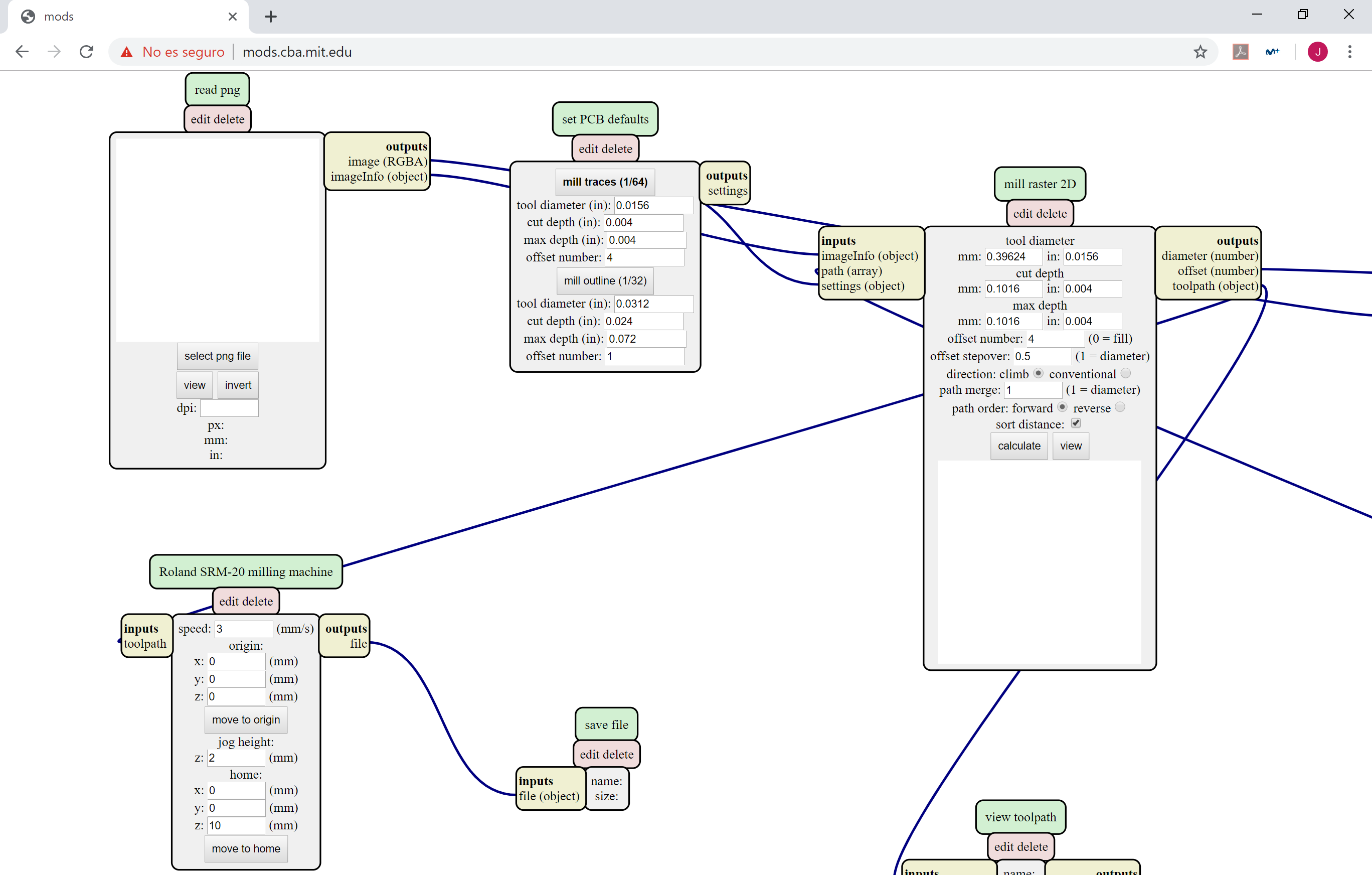
Here are some pictures of the Machine, the process and the result!

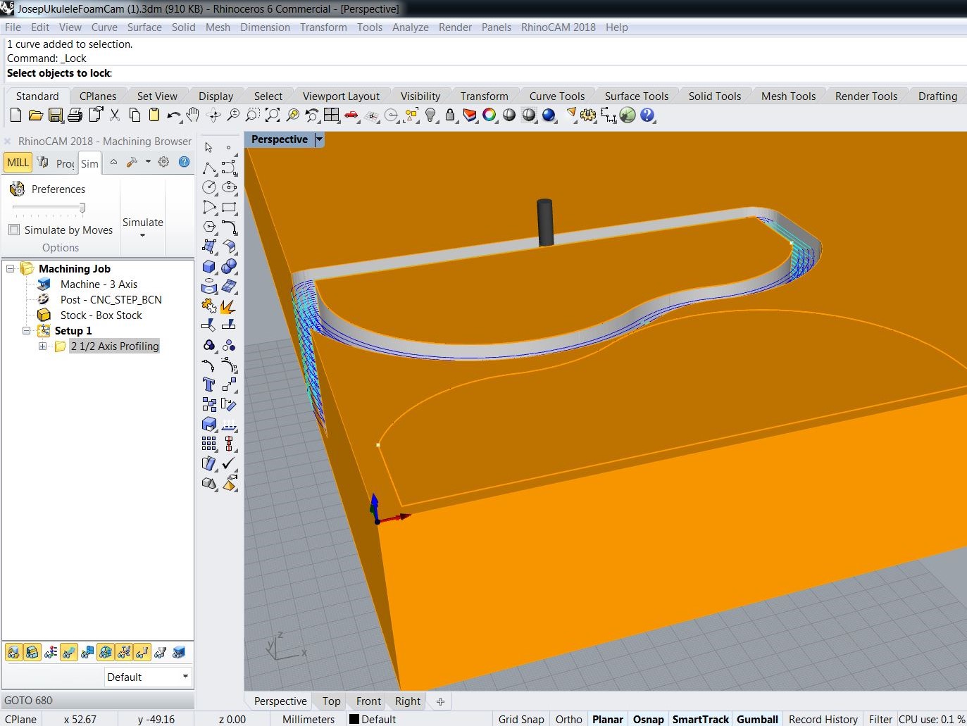
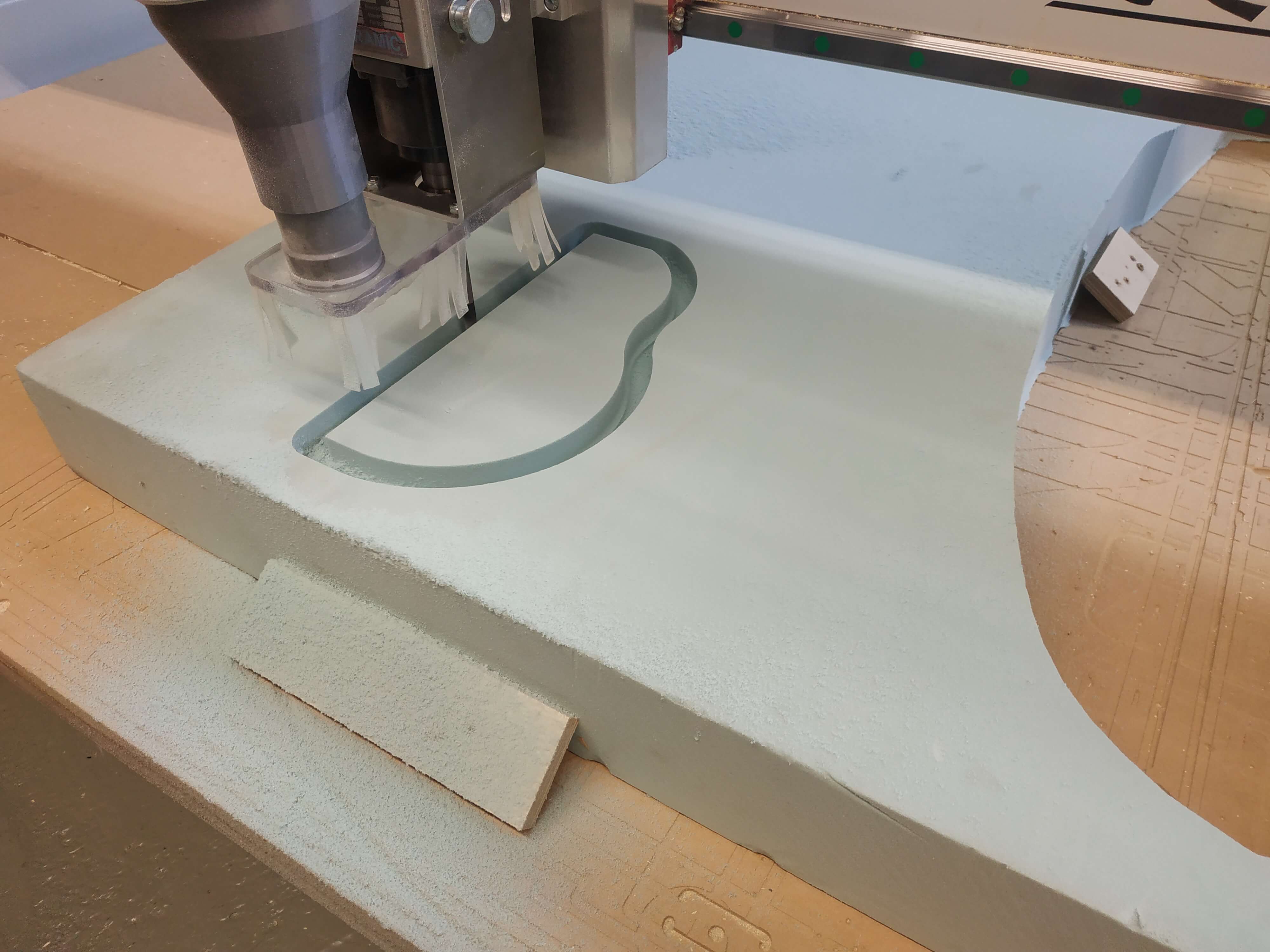
CNC milling
I used the CNC machine of the lab to mill the XPS Foam mold for the wood bending. This was a fast 2D profiling, using a 10 mm Ball end mill. I followed the steps documented in Week 7. I used Rhino CAM for making the files as I explained in Week 17 and then cut it in our CNC. Here are some photos of the process.
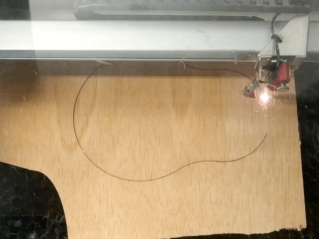
Laser Cut
The laser cut machines where used to cut the wood parts of the body. First the flexible plywood that was bended after, and also the front and back cover. ALso, I designed a first body that was also cutted in the laser. All the process followed to cut them are explained in the WildCard Week documentation.
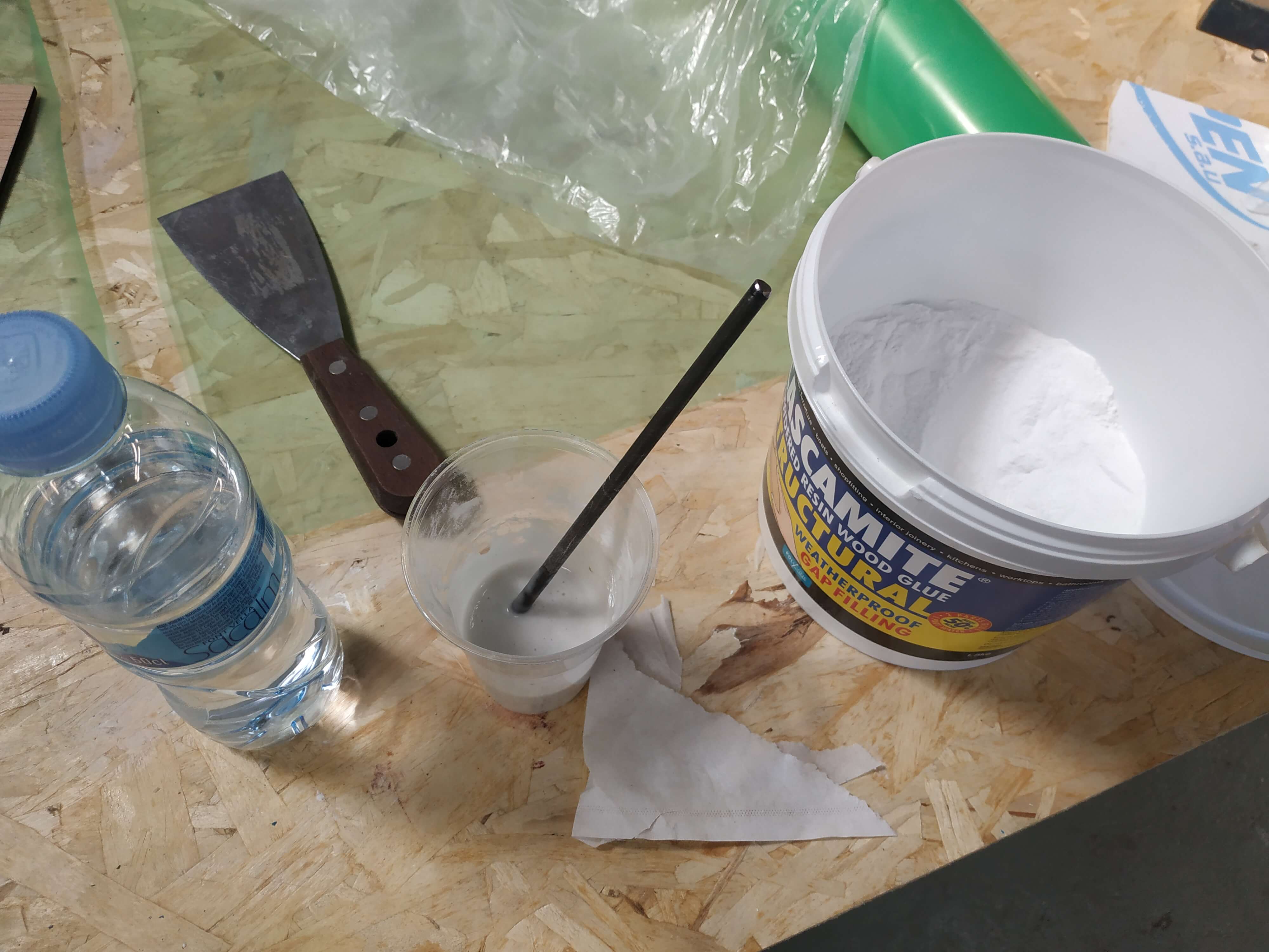
Assembly
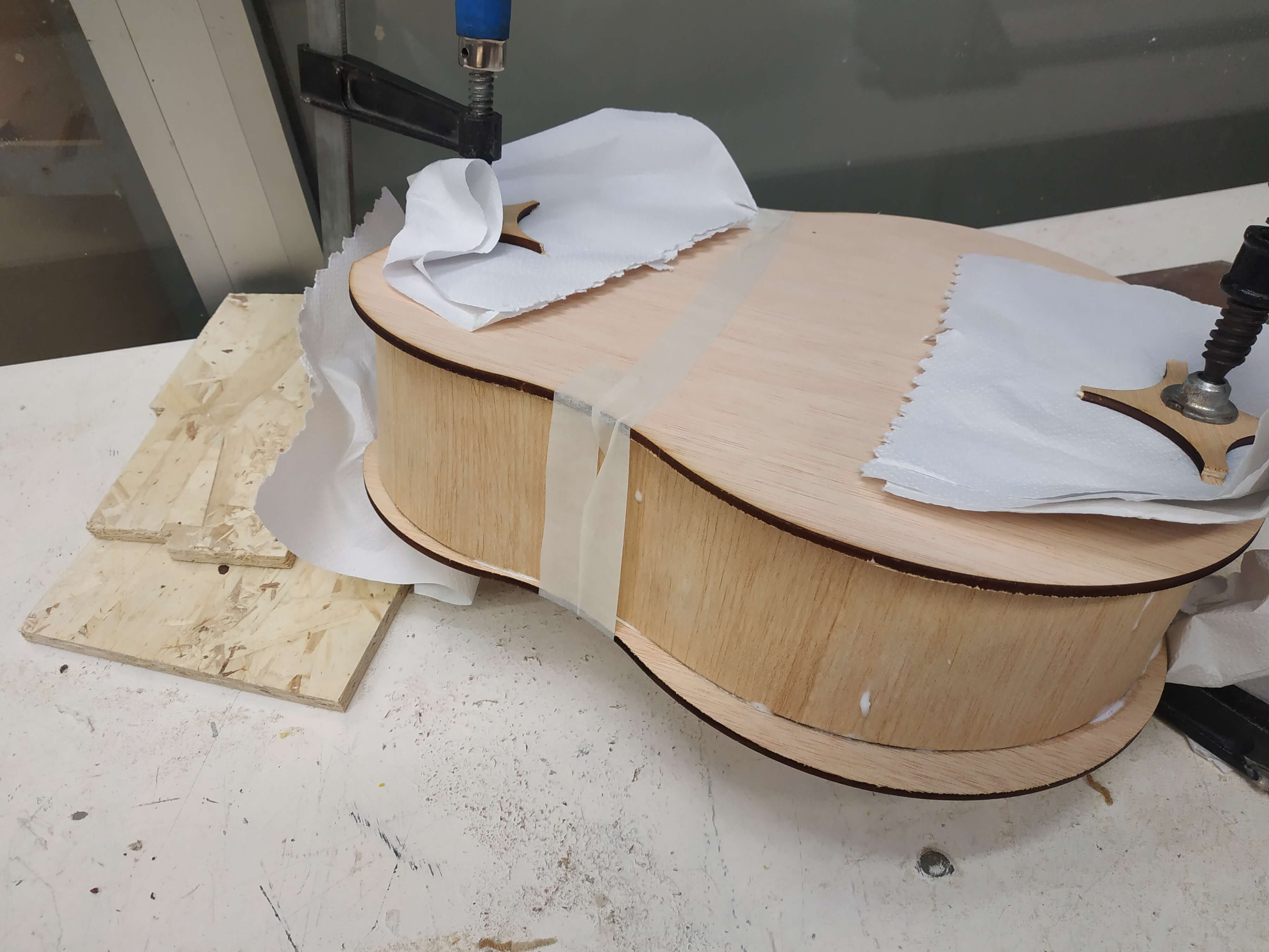
To assembly all the project I used different technics. First I used Cascamite ans white glue for gluing the body wood parts. This wood glue give a nice and solid union, so it was totally perfect for the job.
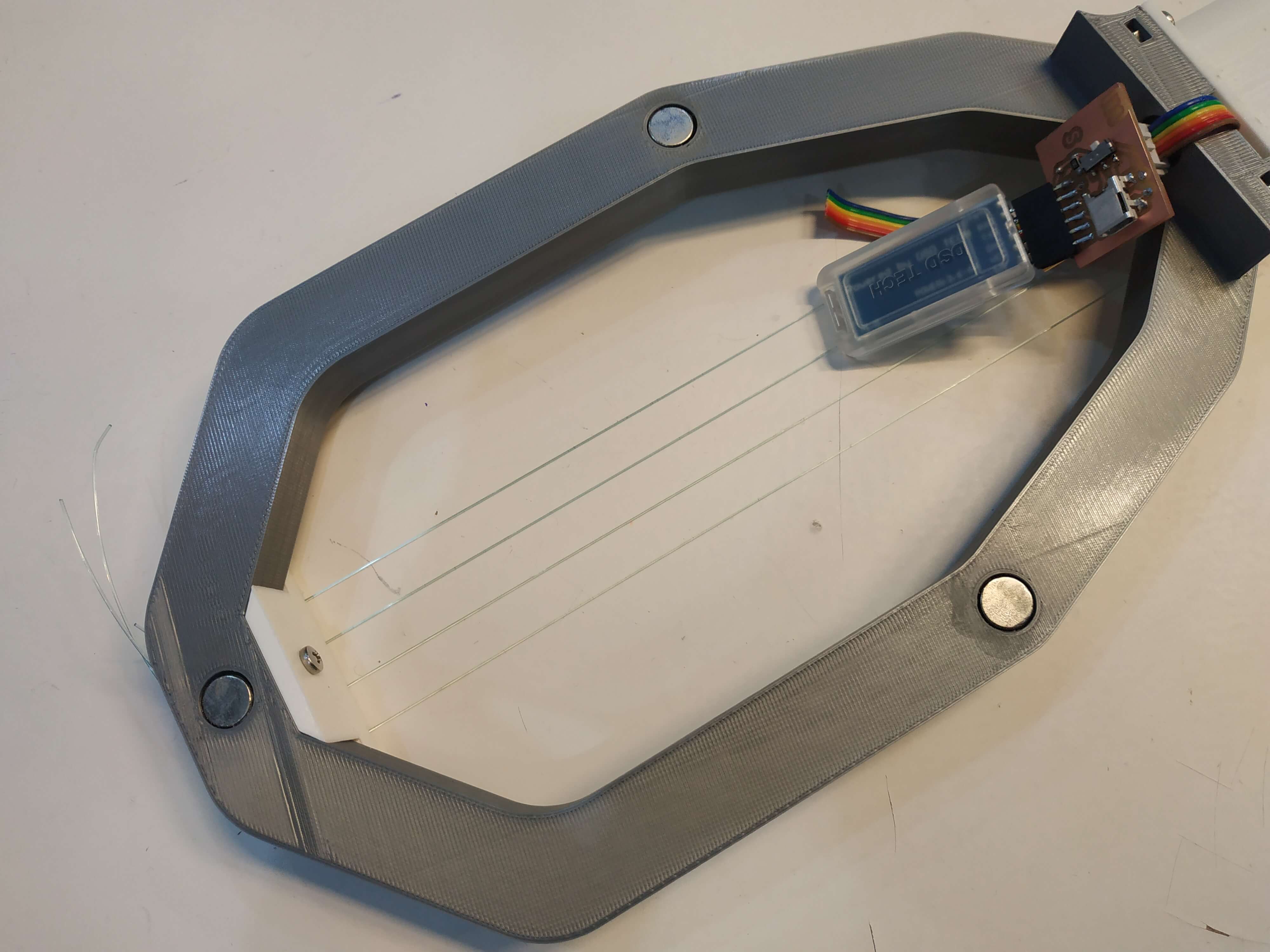
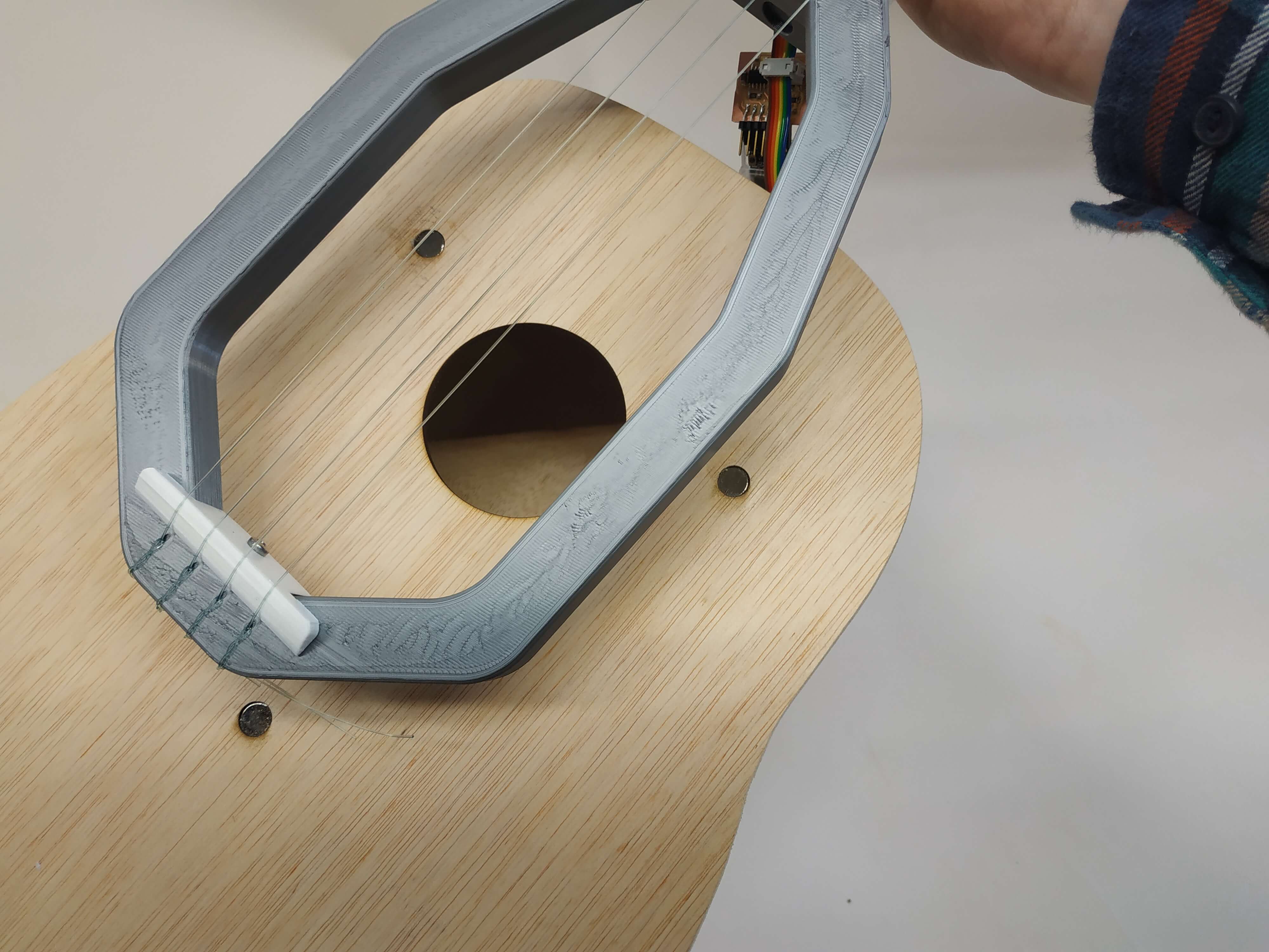
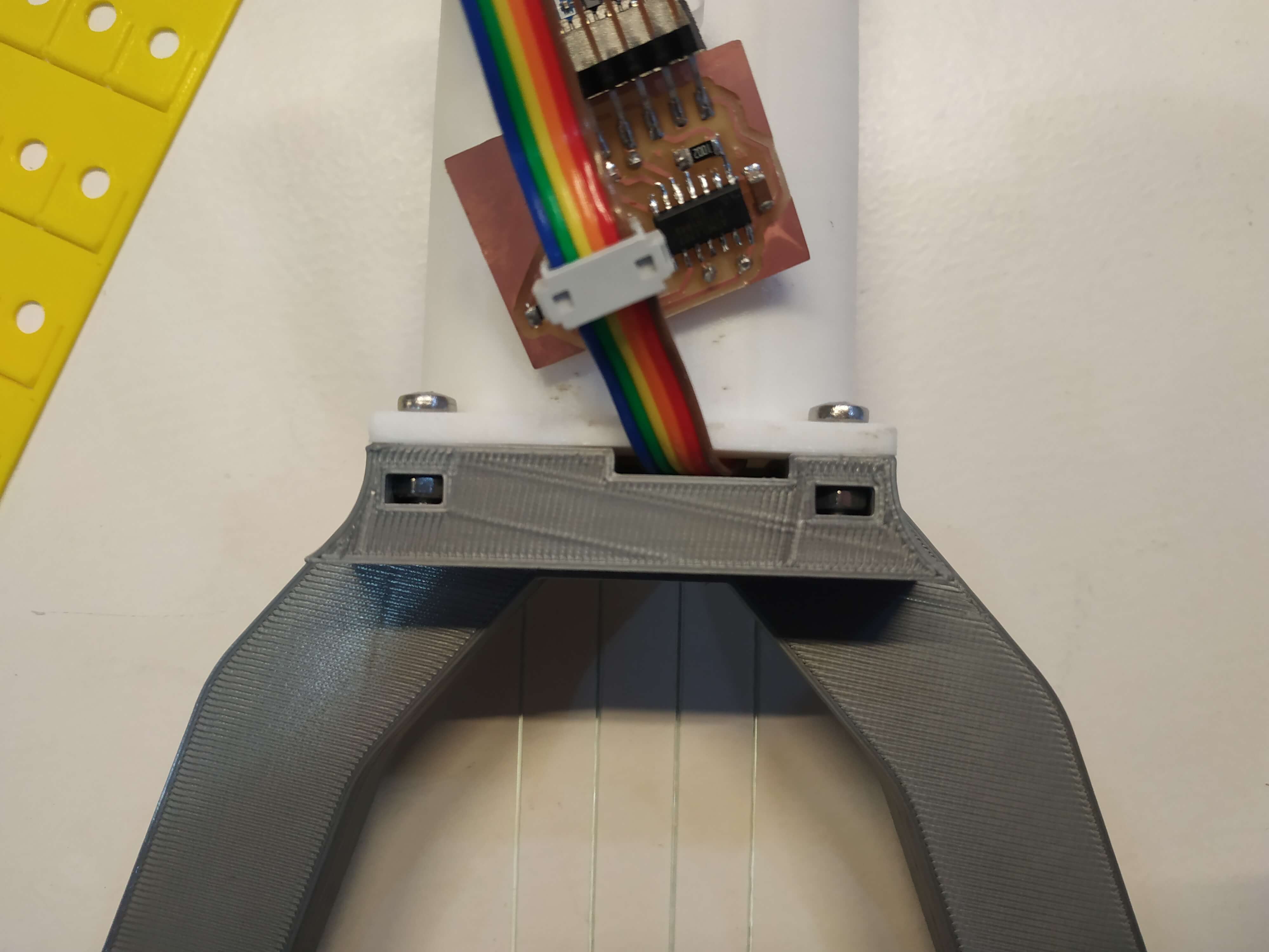
For the 3D printed parts I decided to design some holes for M3 bolts and nuts to ensure the join between them. Check this photos, there are 2 bolts for the jin between the neck and the Body, 2 between the Neck and the Head an one for each tunning peg.
Finally, between the main structure and the body, I designed the exact holes to fit magnets. Those magnets are Neodymium magnets really strong, and are able to support the weight of the bodies. I stick them inside the 3D printed part with super glue, and to the wood with pressure.