5 - 3D Scanning and Printing
Group Assignment
Participants
Felipe Santos, Alberto Lopez, Diar Amin, Gustavo Abreu,Josep Marti, Eva Blsakova and Juan Carlos Rincón.
Test File
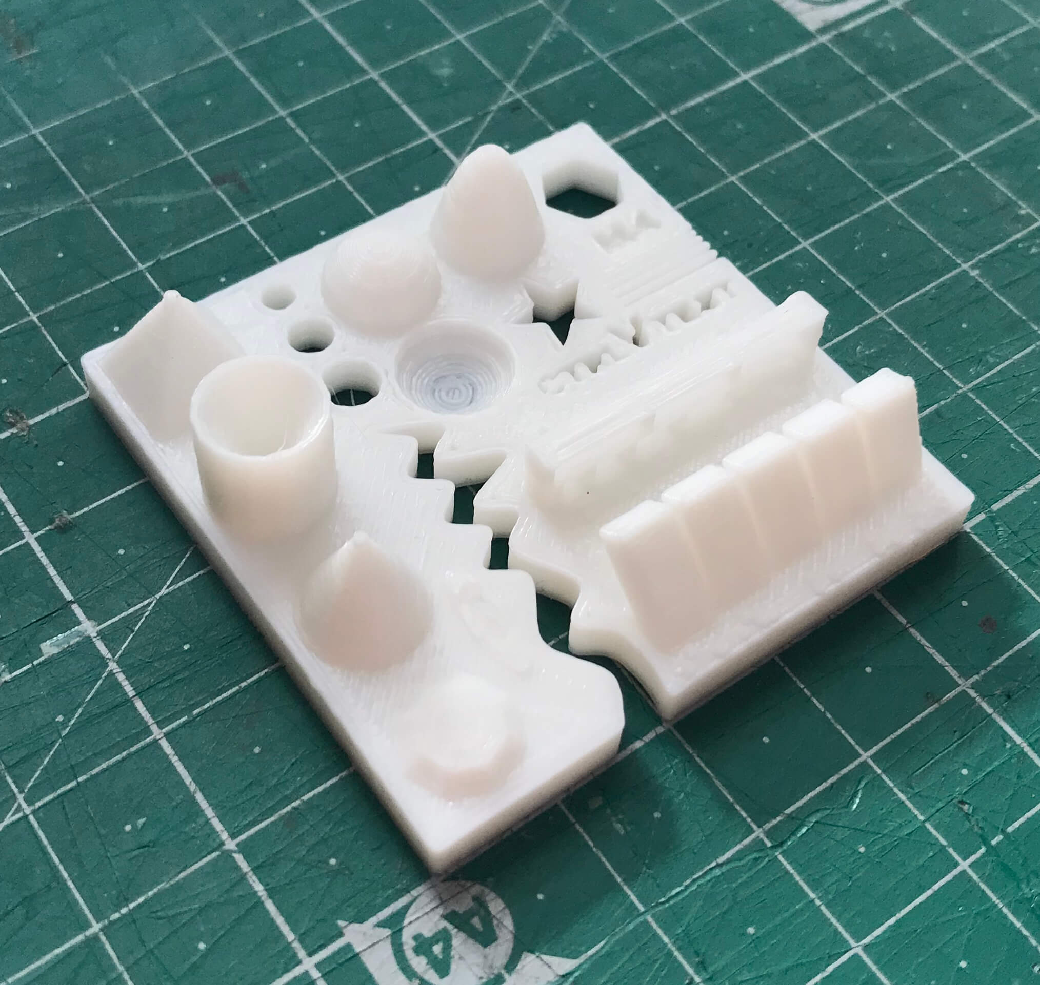
To test the different printers, the best option is to print a part that shows how the printer behaves in different situations. To do this, we've used a file from 3dprint.com available on Thingiverse
.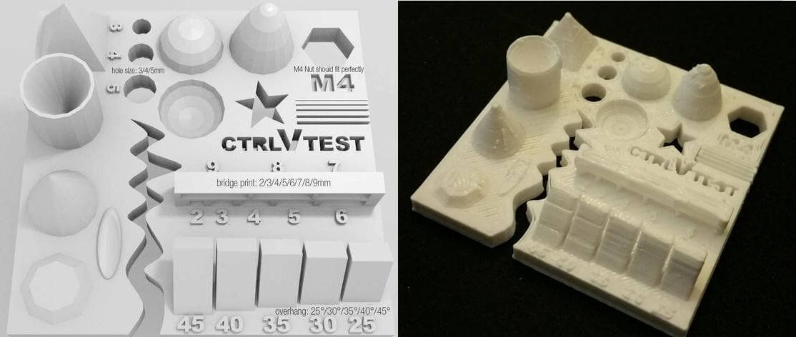
The article explains what should be measured as pointed below:
- Size: the object is 4 x 50 x 50 mm (baseplate) — measure with a caliper.
- Hole size: 3 holes (3/4/5mm) — measure with a caliper/drill.
- Nut size: M4 nut should fit perfectly — insert an M4 nut; it should need a little pressure.
- Fine details: pyramid, cone, all numbers — check if all things look nice and smooth.
- Rounded print: wave, half sphere — check if all things look nice and smooth.
- Minimum distance between walls: 0.1/0.2/0.3/0.4/0.5 mm — depending on your nozzle size and slicer settings you will get different results.
- Overhang: 25°/30°/35°/40°/45° — depending on printed material/cooling, these will not be as seen on the rendering provided.
- Flatness: all flat areas — these should be flat with no gaps.
We’ve used the same slicing parameters on every machine to have somewhat similar results. Although we could not use the same filament since the diameters were different.
Slicing settings:
Layer height: 0.2mm
Wall line count: 2
Top layers: 6
Bottom layers: 4
Infill: 20%
Speed: 60mm/s
Nozzle temp.: 205
Bed temp.: 60
Material: PLA
Printers description
Anycubic Kossel Plus
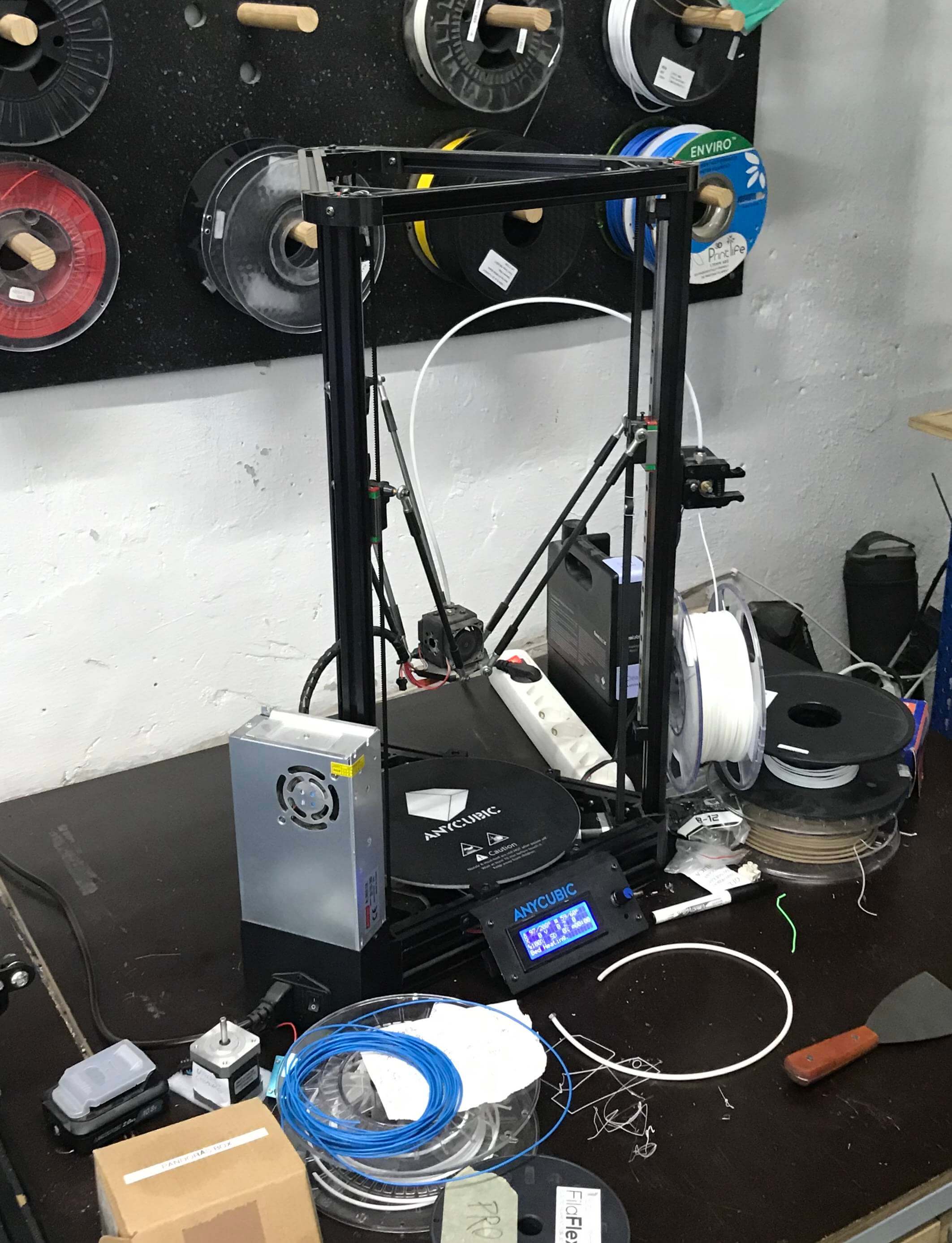
Area (x,y,z): 23x23x30
How to print: SD card
Nozzle diameter: 0.5mm
Filament diameter: 1.75mm
Axis movement: Delta
Ultimaker 2
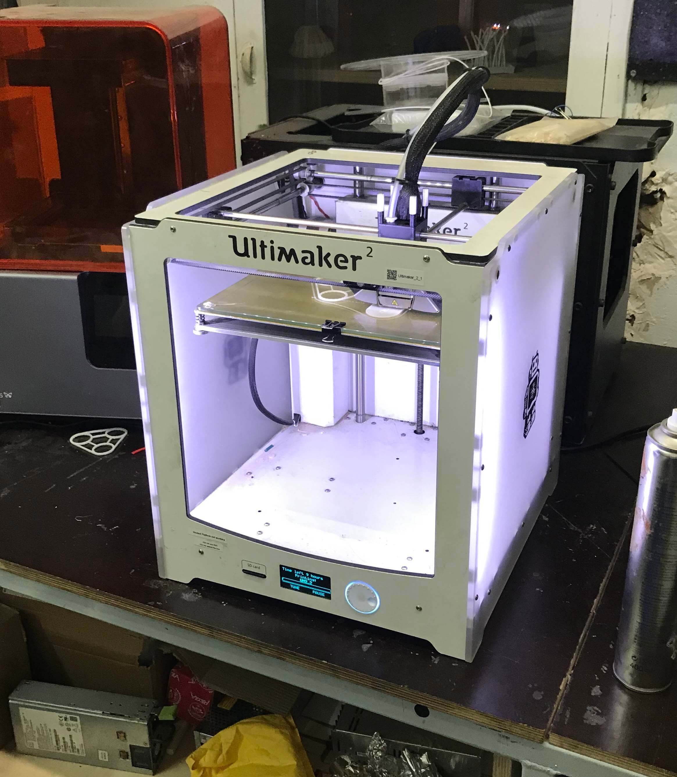
Area (x,y,z): 22x23x20
How to print: SD card
Nozzle diameter: 0.4mm
Filament diameter: 3mm
Axis movement: CoreXY
Rep Rap
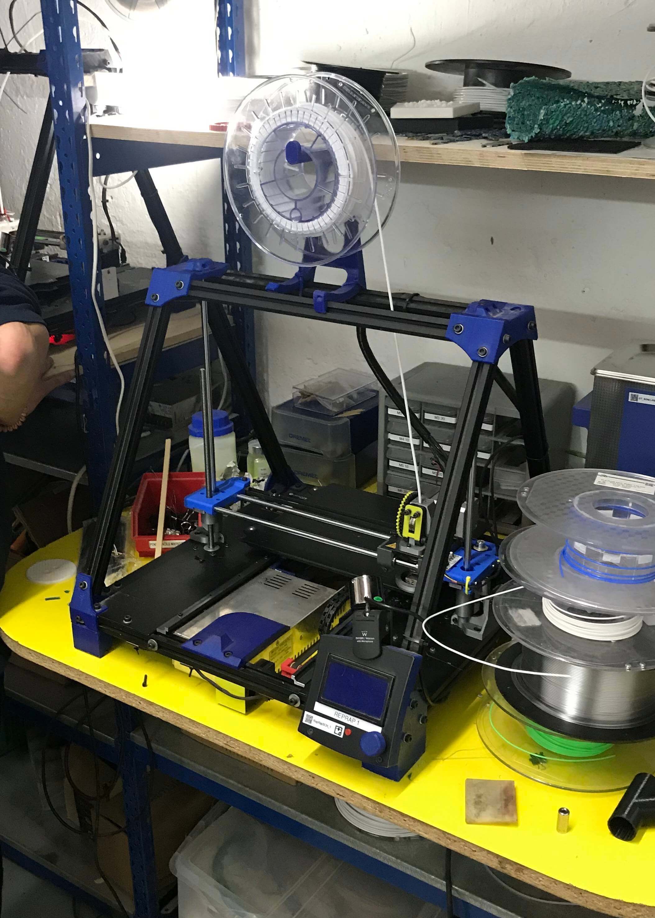
Area (x,y,z): 24x23x20
How to print: SD card or Octoprint
Nozzle diameter: 0.6mm
Filament diameter: 3mm
Axis movement: Cartesian
Prusa i3 MK3
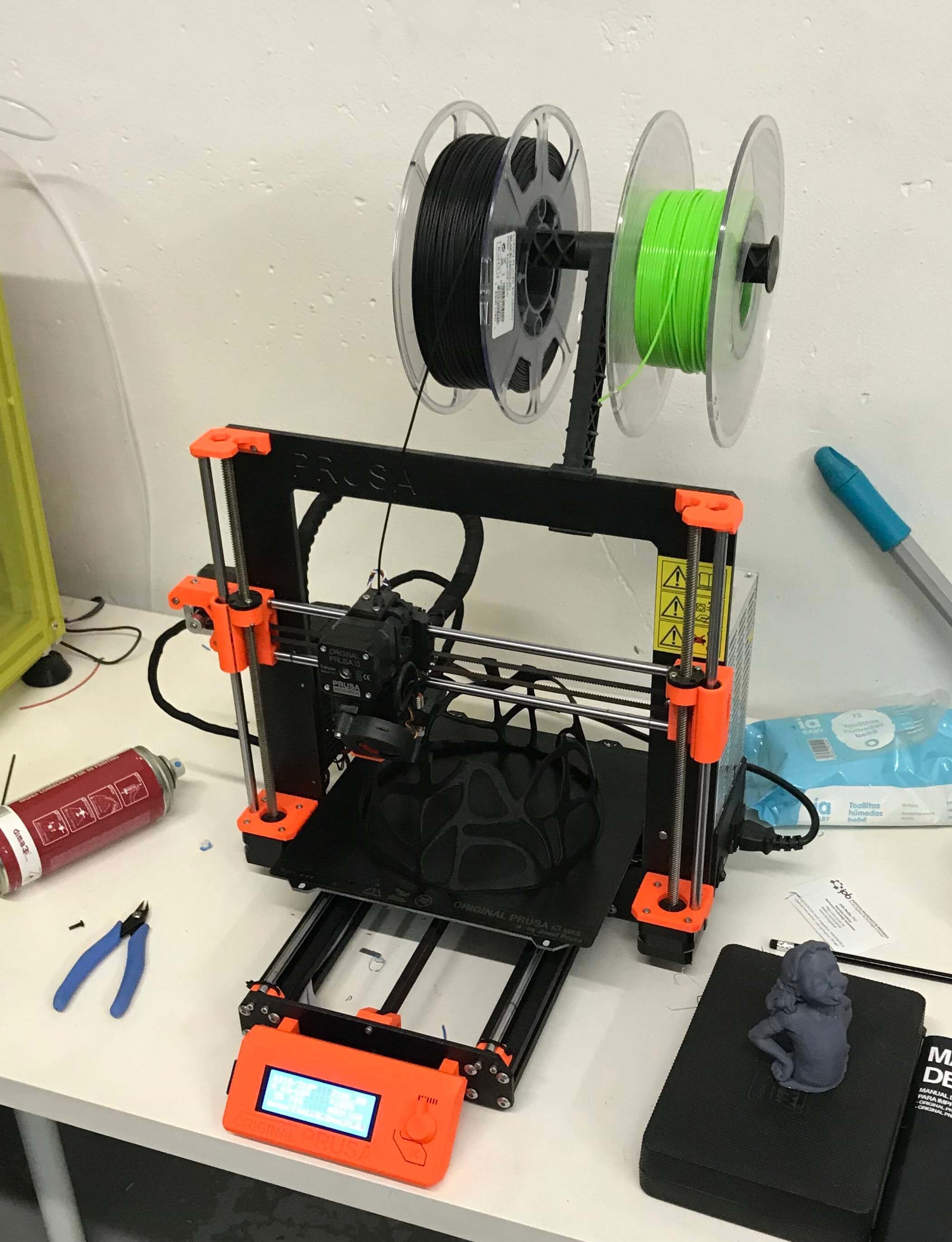
How to print: SD card
Nozzle diameter: 0.4mm
Filament diameter: 1.75mm
Axis movement: Cartesian
Print Tests
Prusa i3 MK3
Size: 4x50x50mm
Hole size: 4.7,3.7,2.5
Nut size: Snug fit
Fine details: Smooth
Rounded print: Smooth
Minimum distance between walls: 0.3mm
Overhang: Up to 45º smooth
Flatness: All closed
Bridges: Up to 9mm smooth
Ultimaker 2
Size: 4x50x50
Hole size: 4.6,3.7,2.3
Nut size: Snug fit
Fine details: Smooth
Rounded print: Smooth
Minimum distance between walls: 0.3mm
Overhang: Up to 45º smooth
Flatness: All closed
Bridges: Up to 9mm smooth
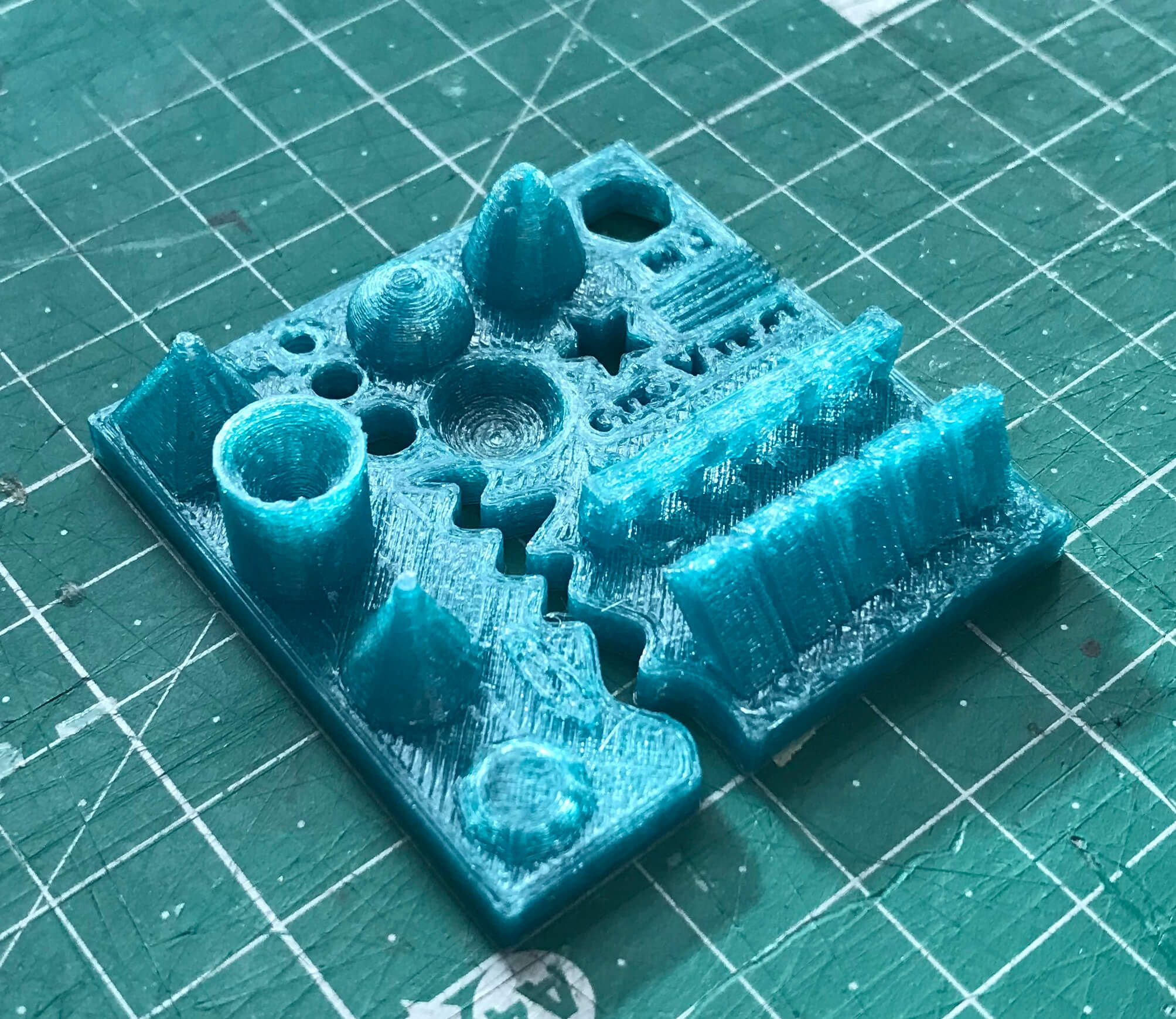
Anycubic
Size: 4.1 x 50 x 50 mm
Hole size: All of the drills almost fitted
Nut size: Almost fitted but not entirely
Fine details: Looks nice and smooth
Rounded print: Looks nice and smooth
Minimum distance between walls: Problems only with the 0.1/0.2mm wall distances but printed nicely
Overhang: No problem printing the overhangs
Flatness: Flat with no gaps
Bridges: It printed it all but with a little problem in the bridge of 6mm
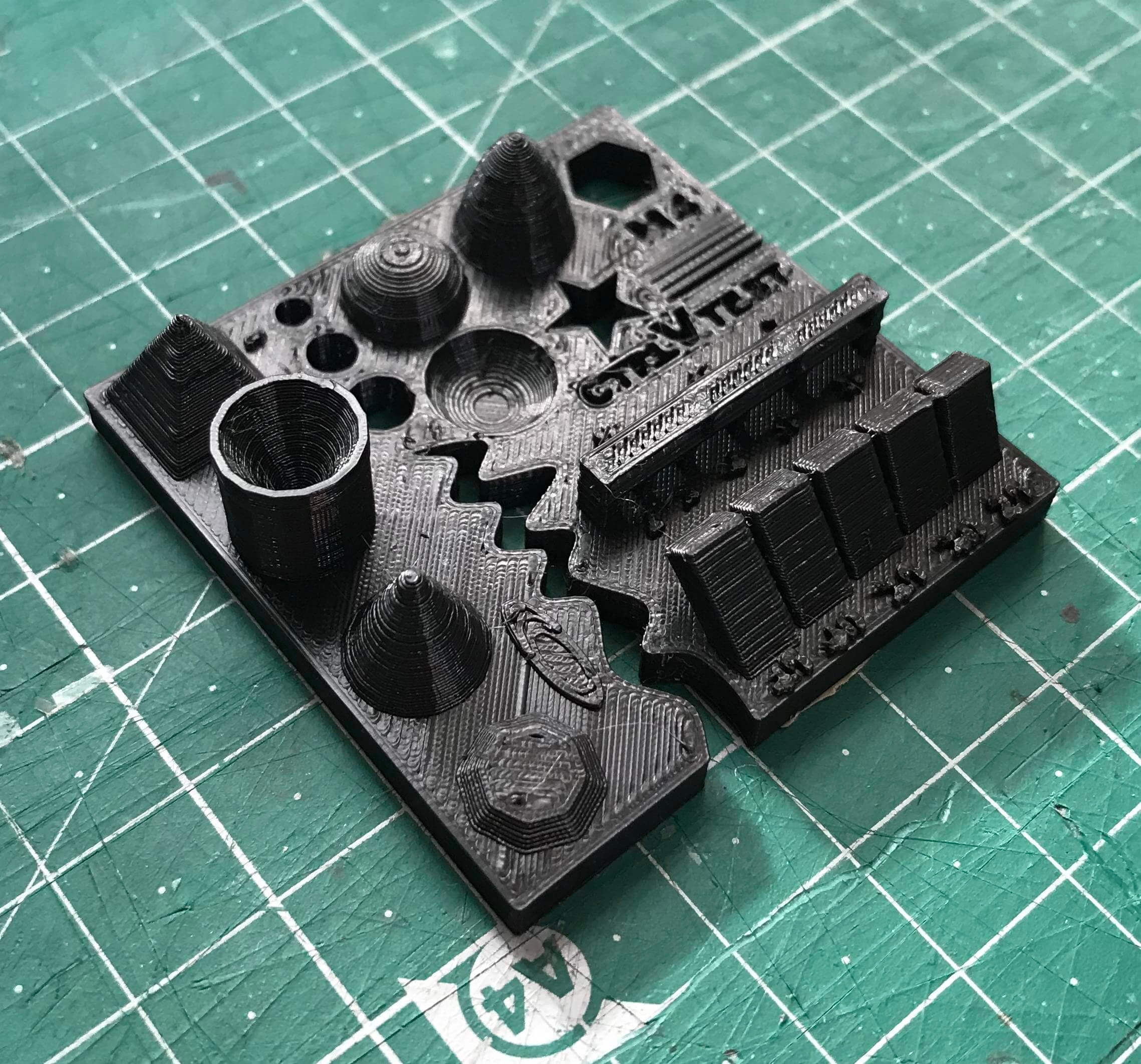
RepRap
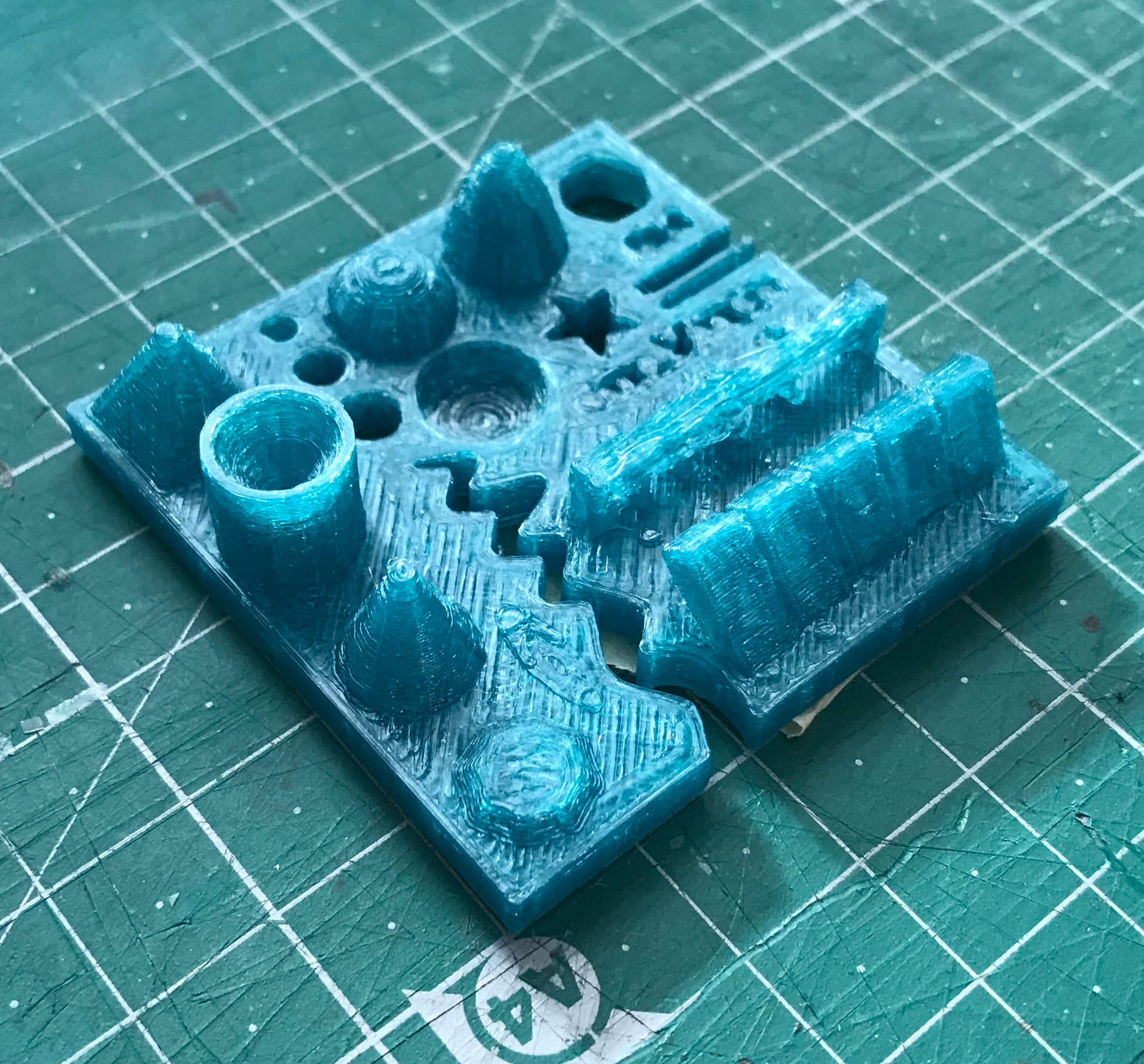
Size: 4.1 x 49 x 49 mm
Hole size: Any of the drills fitted at all
Nut size: Doesn’t fit
Fine details: Looks nice but not smooth
Rounded print: Looks nice but not smooth
Minimum distance between walls: It could print only one wall with wrong distances
Overhang: No problem printing the overhangs
Flatness: Flat with no gaps
Bridges: No bridges at all
Conclusions
The Prusa i3 Mk3 did the best printings with accurate measurements, nice bridges, overhangs, spaces between walls and a lot of details. Anycubic and Ultimaker had similar good results.
The worst result was on the Reprap, we believe we coult fine tune the slicing to improve the print. But, other than it having a 0.6mm nozzle, the main reason could be the old filament we’ve used. We may try again with a new one as soon as it arrives.
Since we had to use different softwares and filament between printers, we had very different results, but overall, they were good prints.
Individual Assignment
I had some previous experience with 3D printing, so I decided to try something new.
Gyroscope
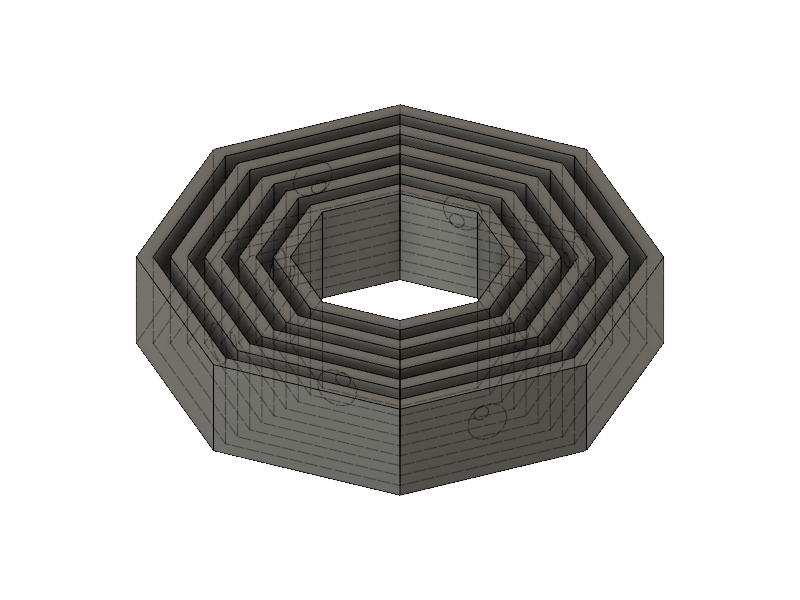
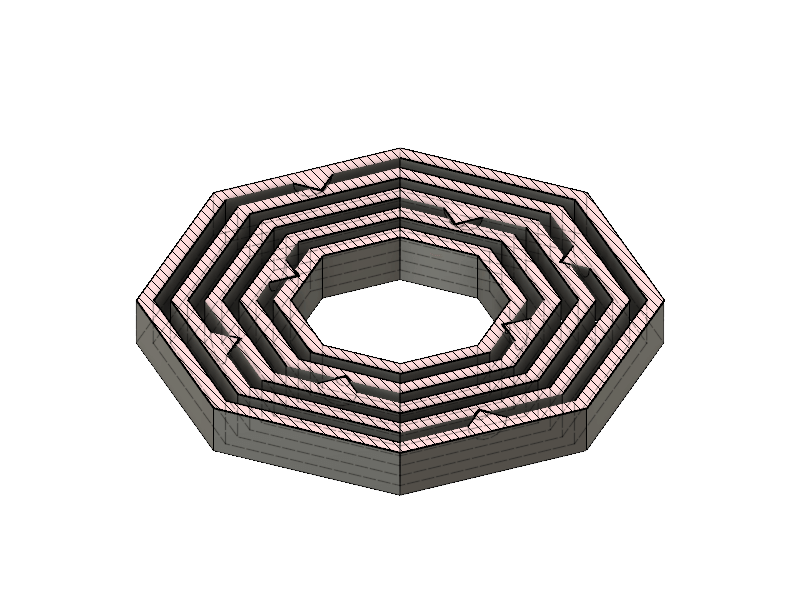
The first thing I wanted to build was a Gyroscope. A gyroscope is made out of different parts assembled together that allow them to spin in different ways. The most interesting thing is that you can 3D print it all together, and it is impossible to do it in a subtractive way.
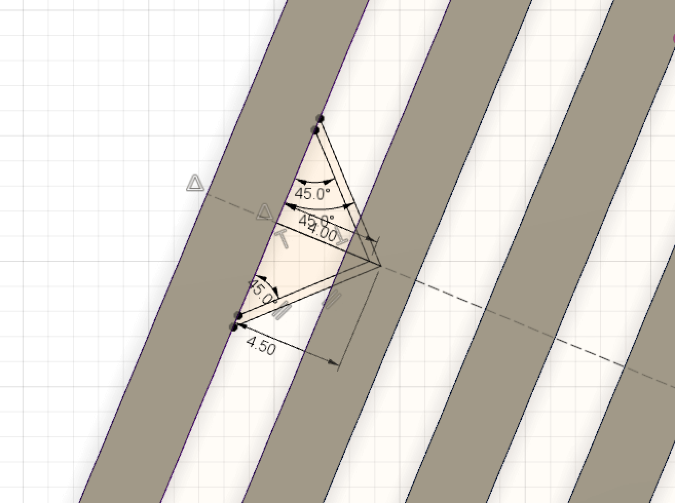
The design was done in Fusion 360. The idea was to have 5 different bodies with some joints that let them rotate on an axis of the object on top of it. The joins where just conics forms for the join and the hole, giving it a spacing of 1 mm to have separate parts. It is important to make sure that the angles of the joins are 45º, if not the print can go wrong and get the 2 parts sticked together.
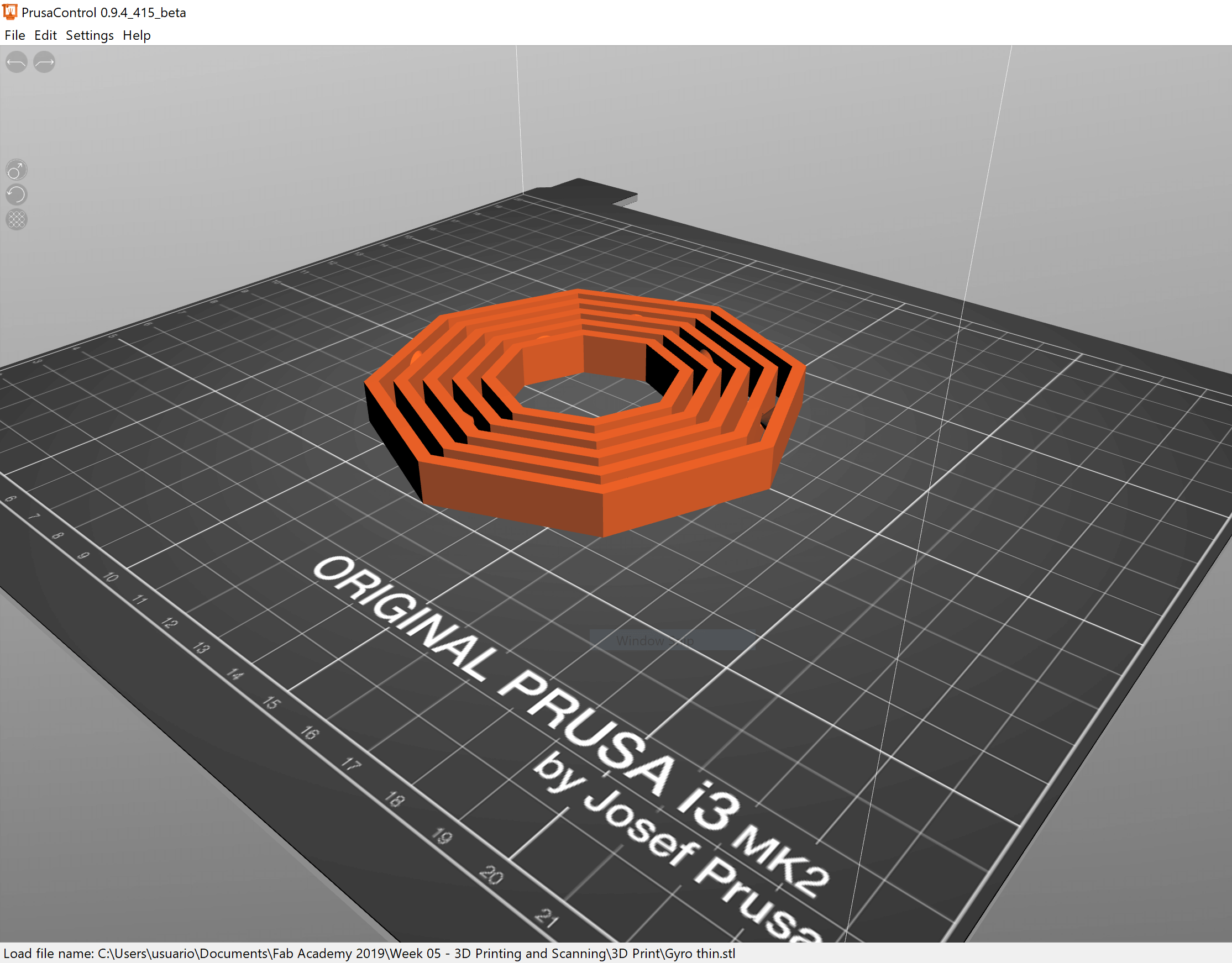
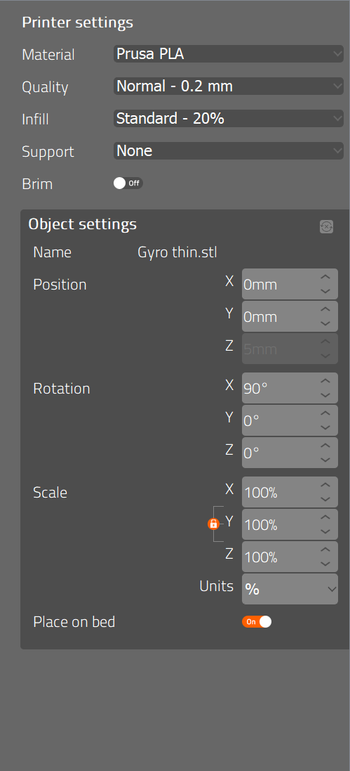
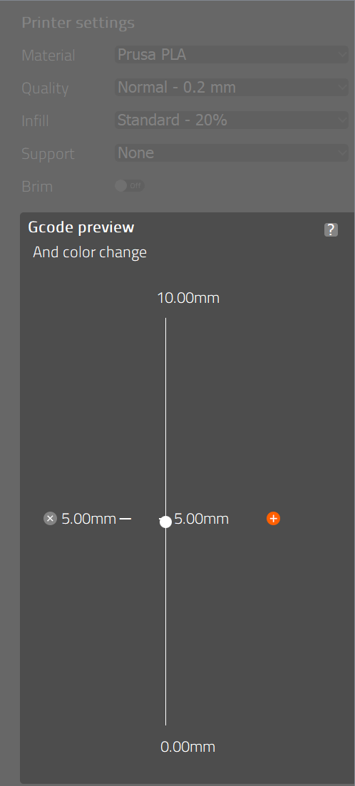
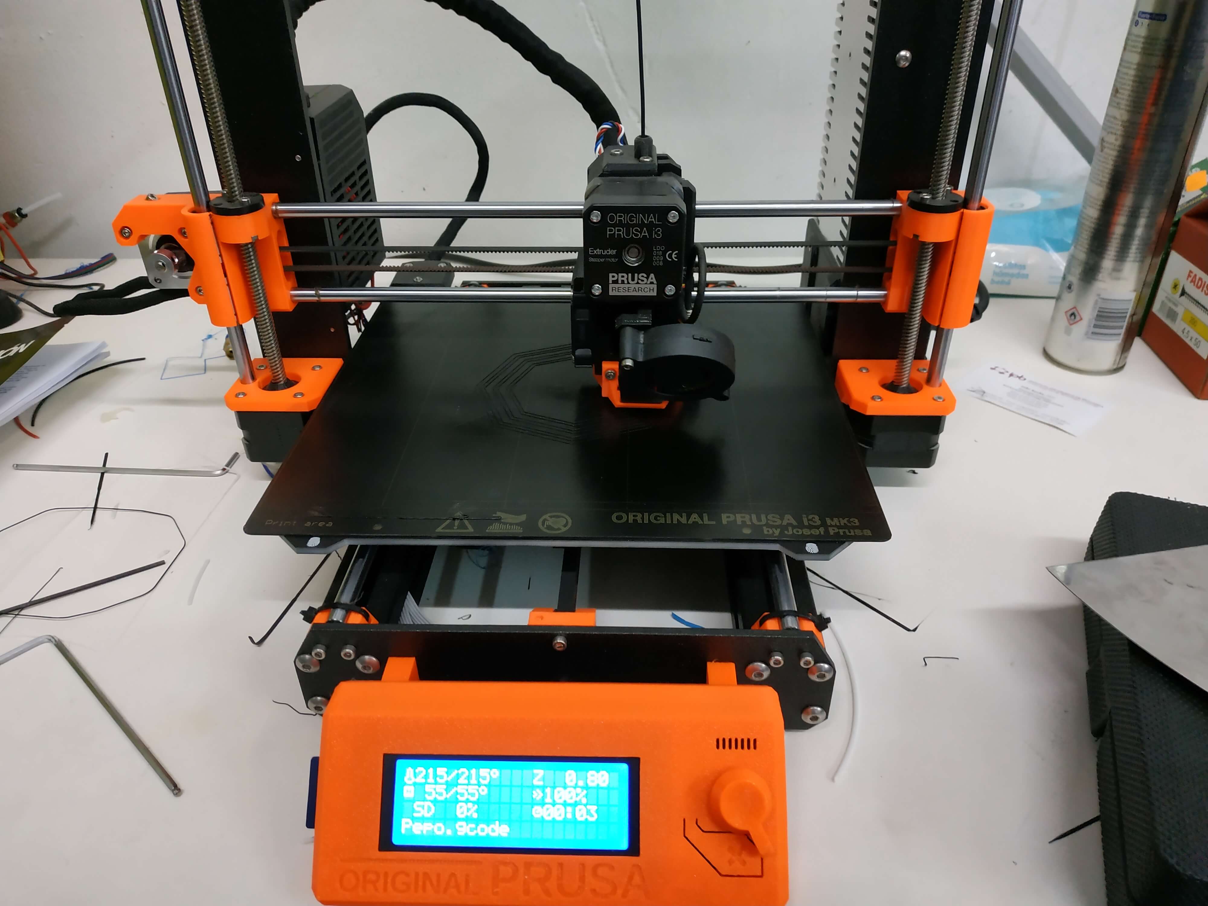
I decided to print it on the Prusa printer because I am used to work with it and because it was available. For this design as it is really simple I used the Prusa Control software and I set the printer to work with PLA, the temperature is set automatically to 215º for the nozzle and 55º for the bed, a Normal quality with a layer height of 0.2mm and an infill of 20%. There were no supports needed. In the middle of the print I set a stop at 5mm height to change the colour.All set up, I grabbed the gcode produced by the software, copy it to the SD card and print it.
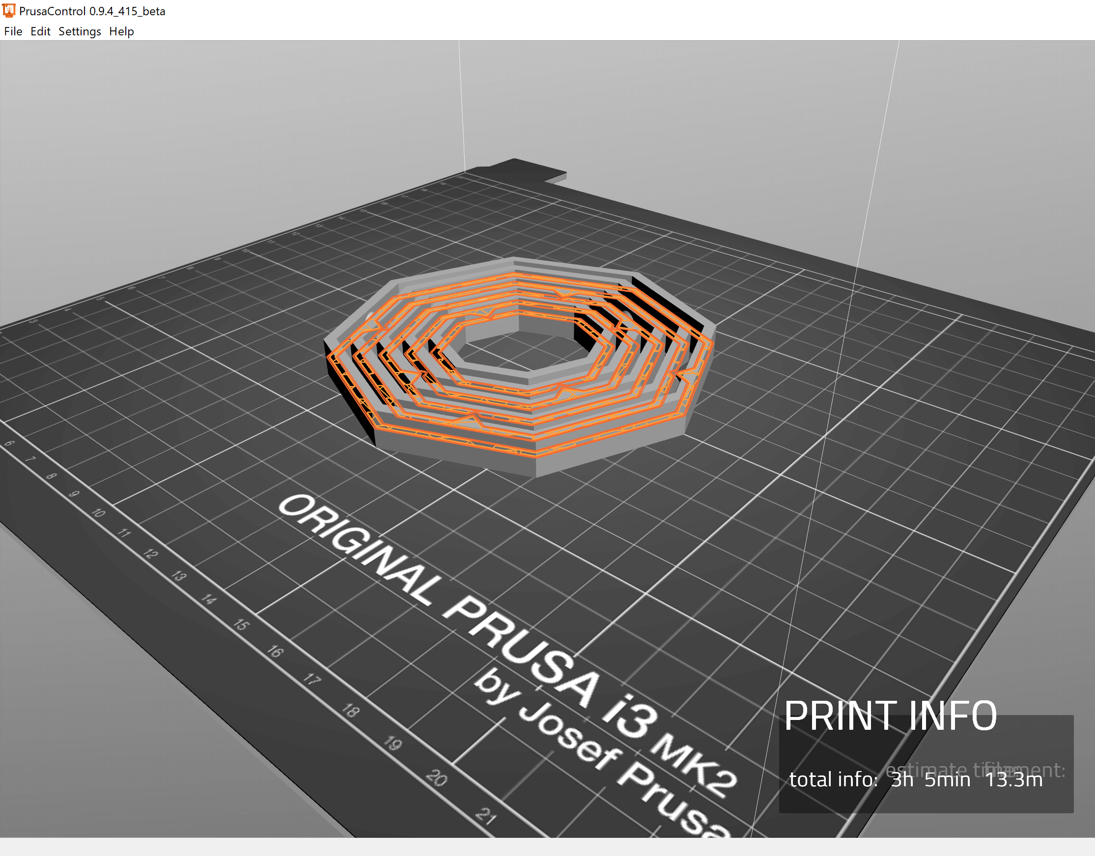
The print was long, 3 hours and 20 minutes, because it was quite a big piece. Also, I spend 5 minutes changing the filament when I had the half of it printed. The result was really good, but there was a design mistake, the joins were not too deep, and as it has a little bit of flexibility it is easy to take the different pieces apart. I will re-do it again with better joins, but the result was totally amazing!
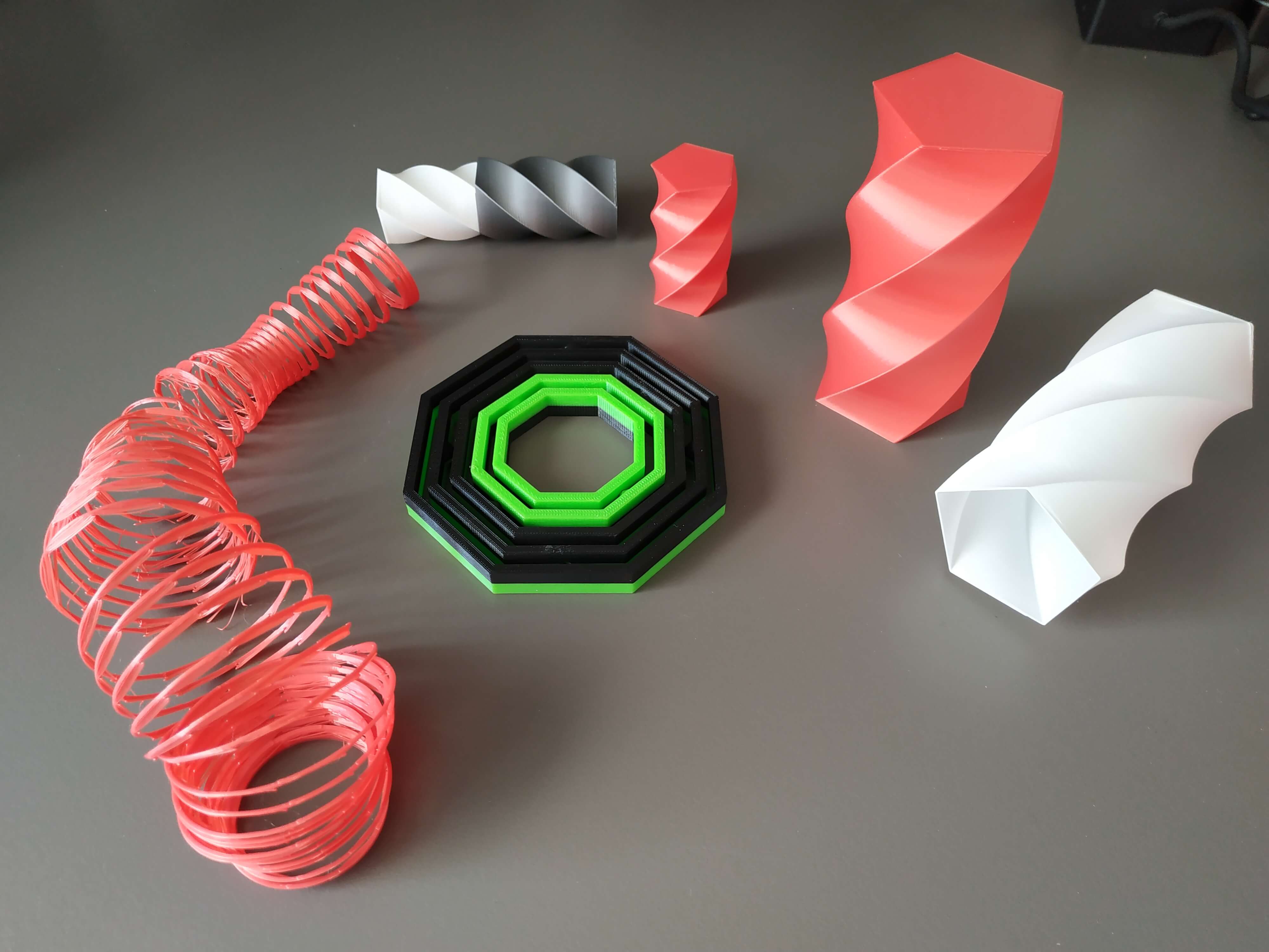
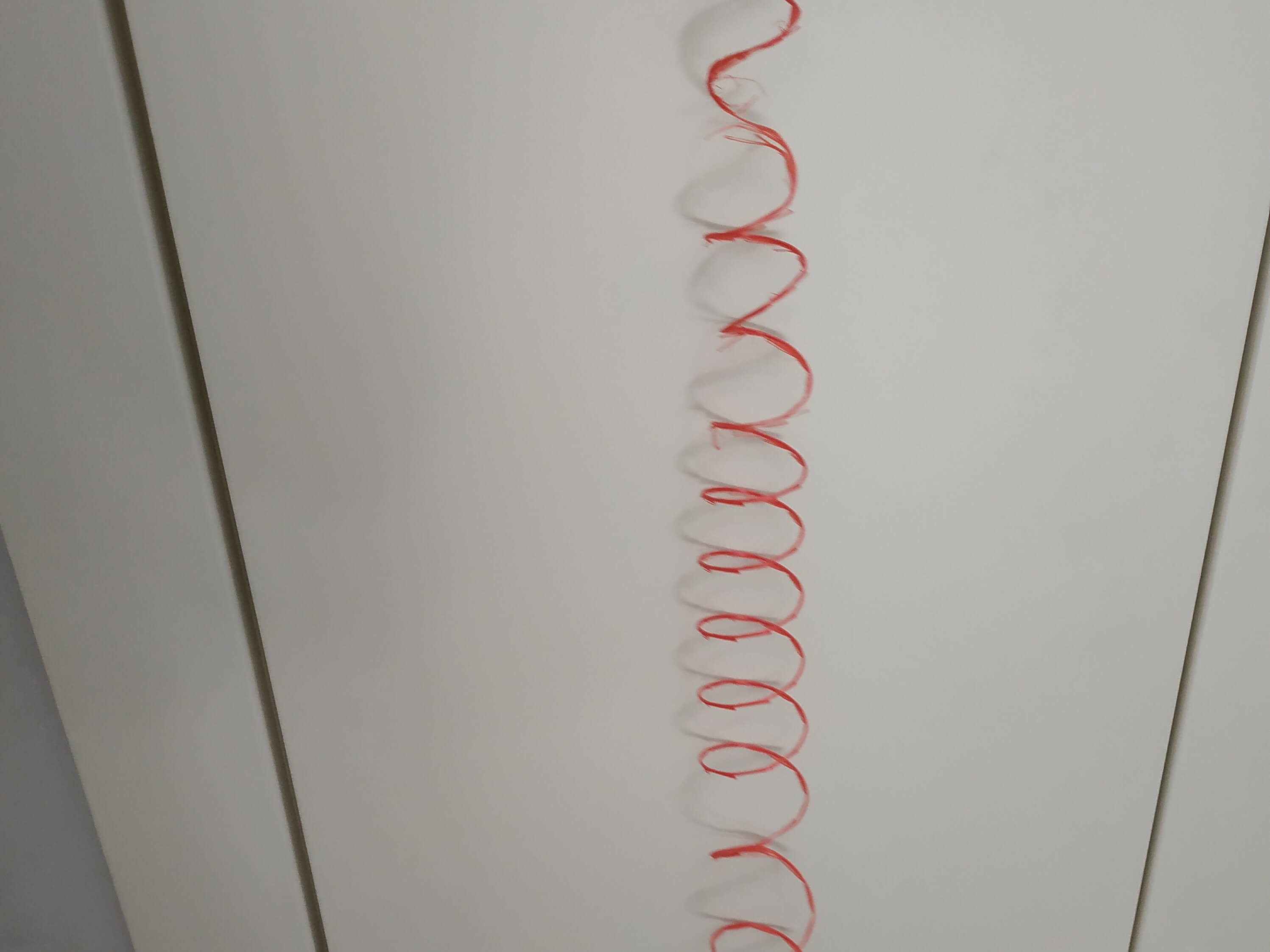
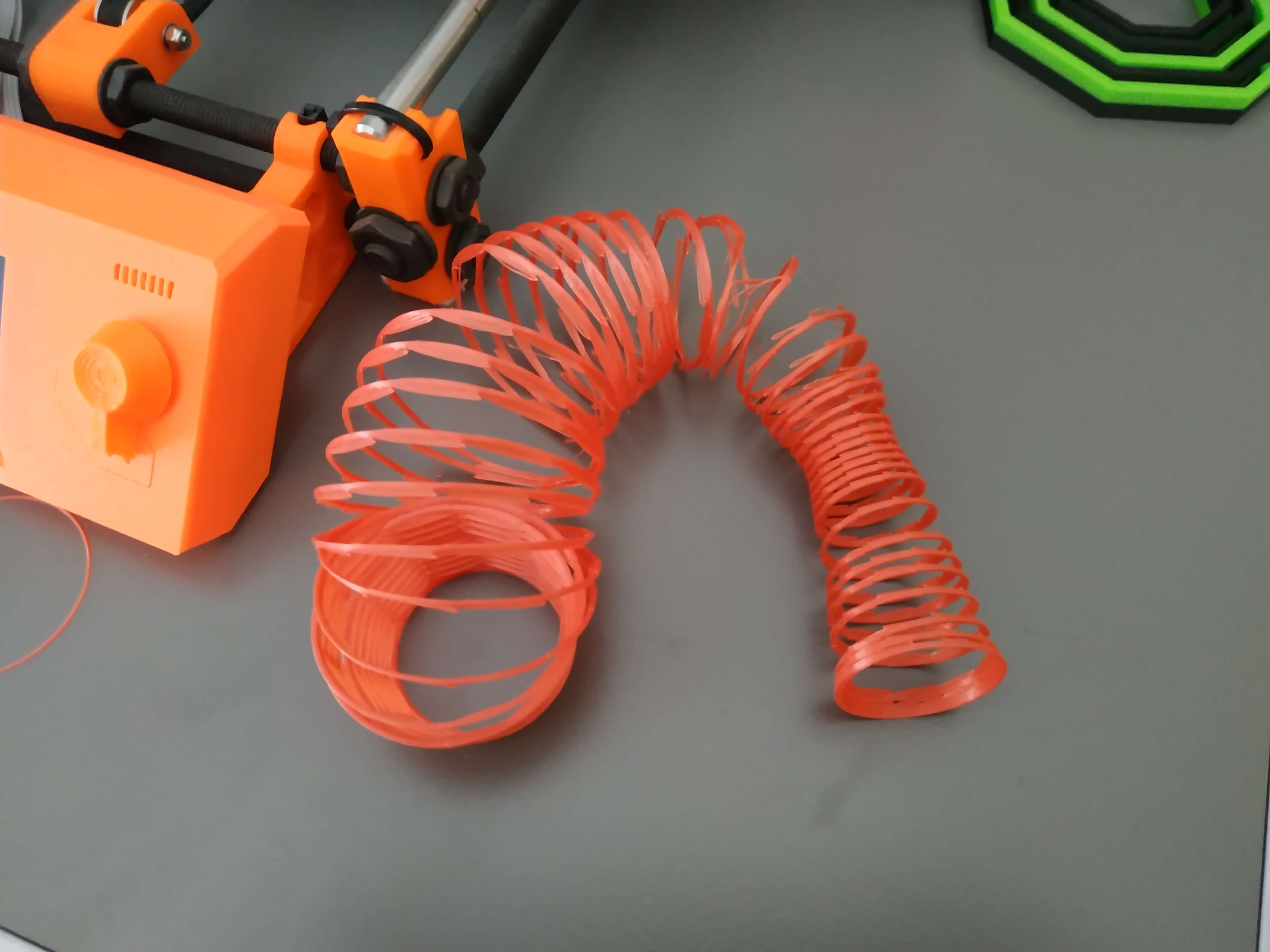
Spring shape
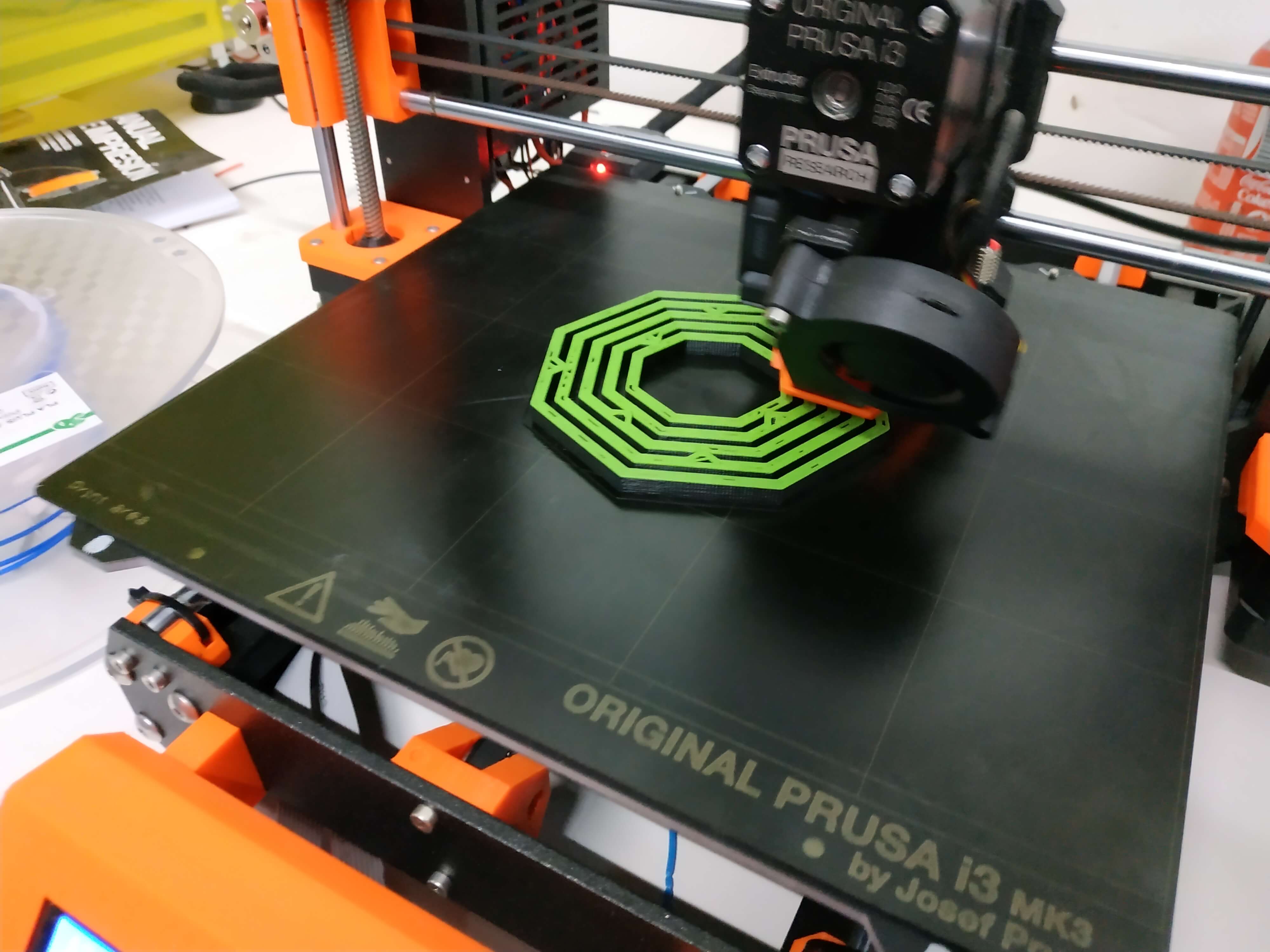
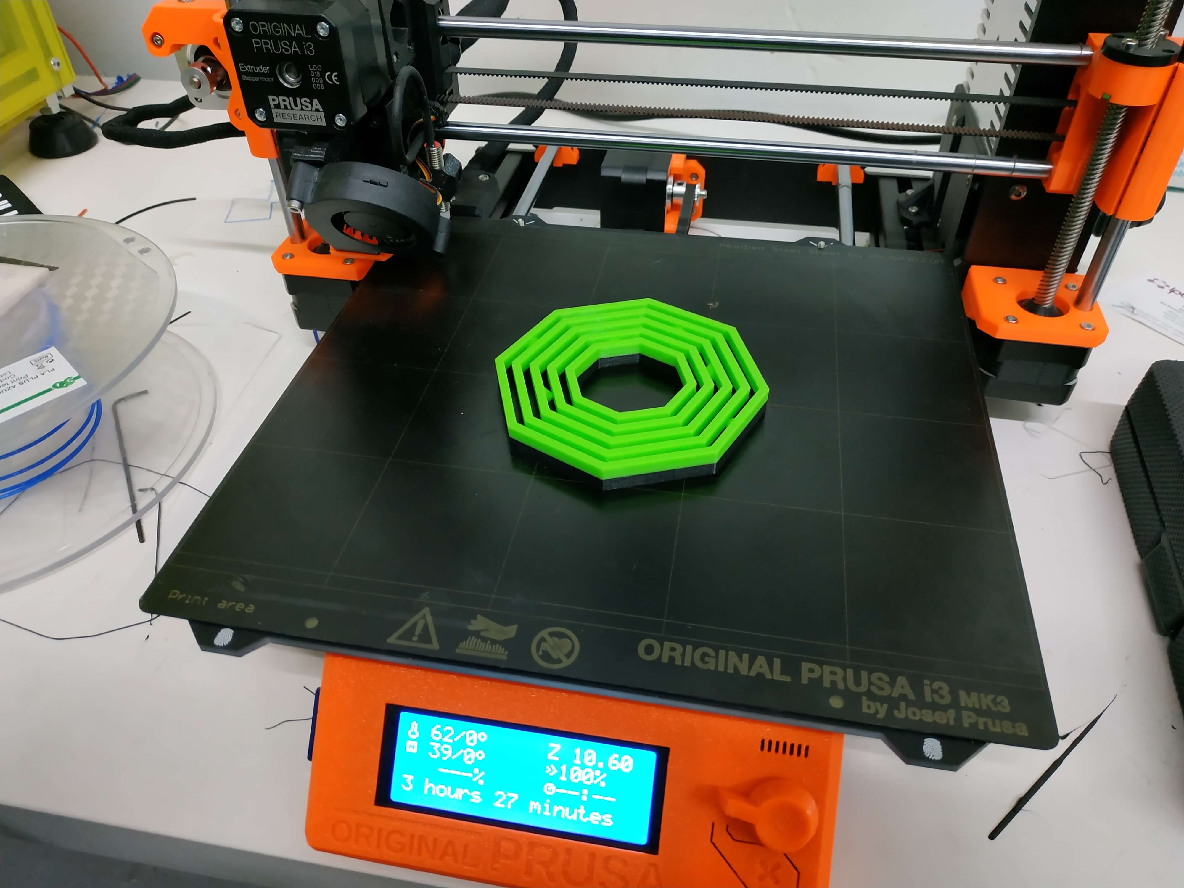
After the gyroscope, I decided to try a new technique, to print an object formed by a spring. The idea is to layer your object as a spring, so I designed a coil in Fusion 360 and then cut the shape of my object.
To print it, I used the same parameters as the gyroscope, 0.2 layer height and no infill. The software I used was also the Prusa Control, because it is simple and it has everything I needed for this print. The printing time was 1 hour and 43 minutes. The result seemed great, but it was fragile and when I tried to get the different filament apart, it was stiked and it seems like I was breaking it. Finally, I got the spring, but was too thin, so the structure doesn't stand for its own. I had to try to do a new one with a bigger thickness.
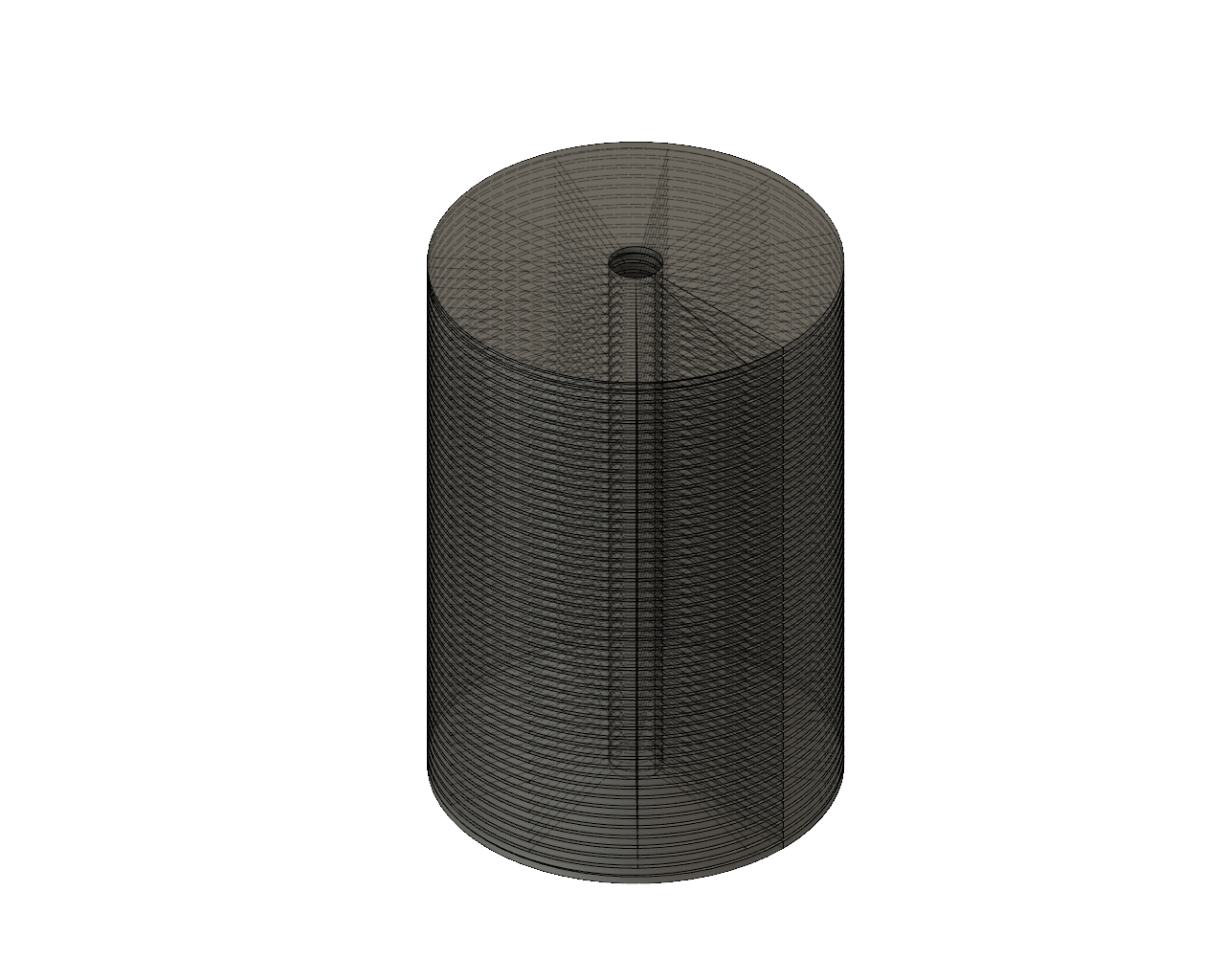
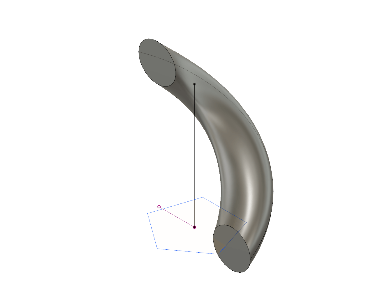
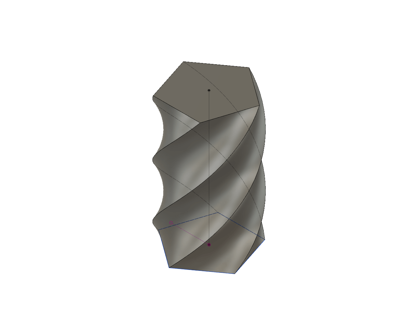
Twisty boxes
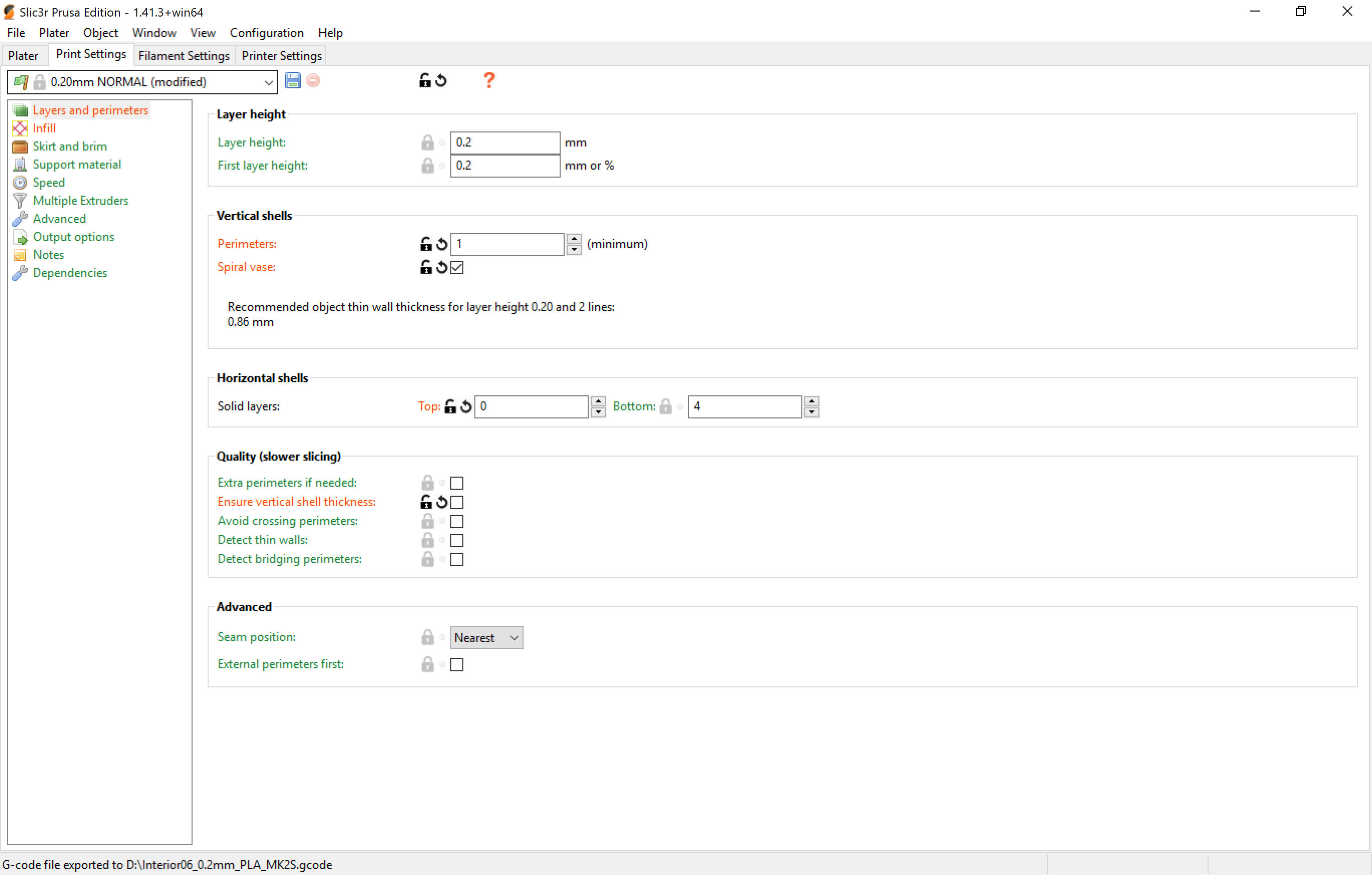
Last but not least, I wanted to try to print something using Vase Mode, a printing mode where the print is not done by layers at the same Z, but the Z axis is allways going up in a spiral movement. I find it so cool and it is much faster, but the bad thing is that you cannot control the thikness of your vase, it will be the size of the nozzle and you can only print objects with one perimeter.
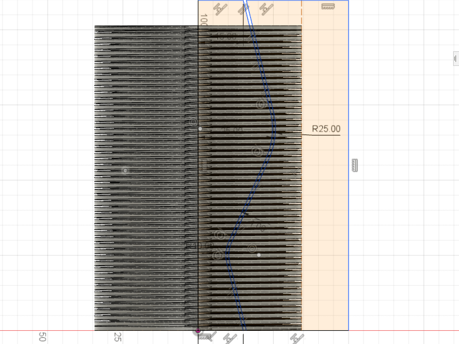
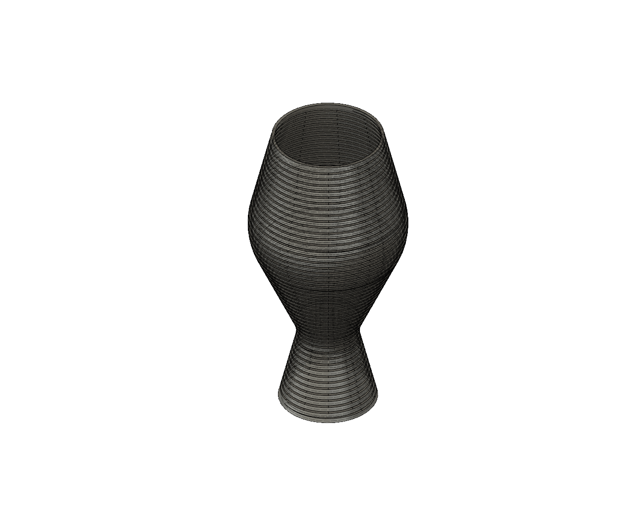
To do so, I get an idea from Desktop Makes for making a twisty box. The idea is to do two spiralized vases with some tolerance and so they can be assembled one inside the other creating a nice flow between them when entering. The design was done in Fusion 360 too, I used a pentagon as a base and a coil to do the swap. It is a fully parametric design, so you can change the parameters and have new vases.
With this design I used the software Slicer PE because I needed more settings than the ones offered in the Prusa Control software. To do it I had to set the Vase-Mode as you can see in the image. The layer height I used 0.2, the standard one as it was a test.
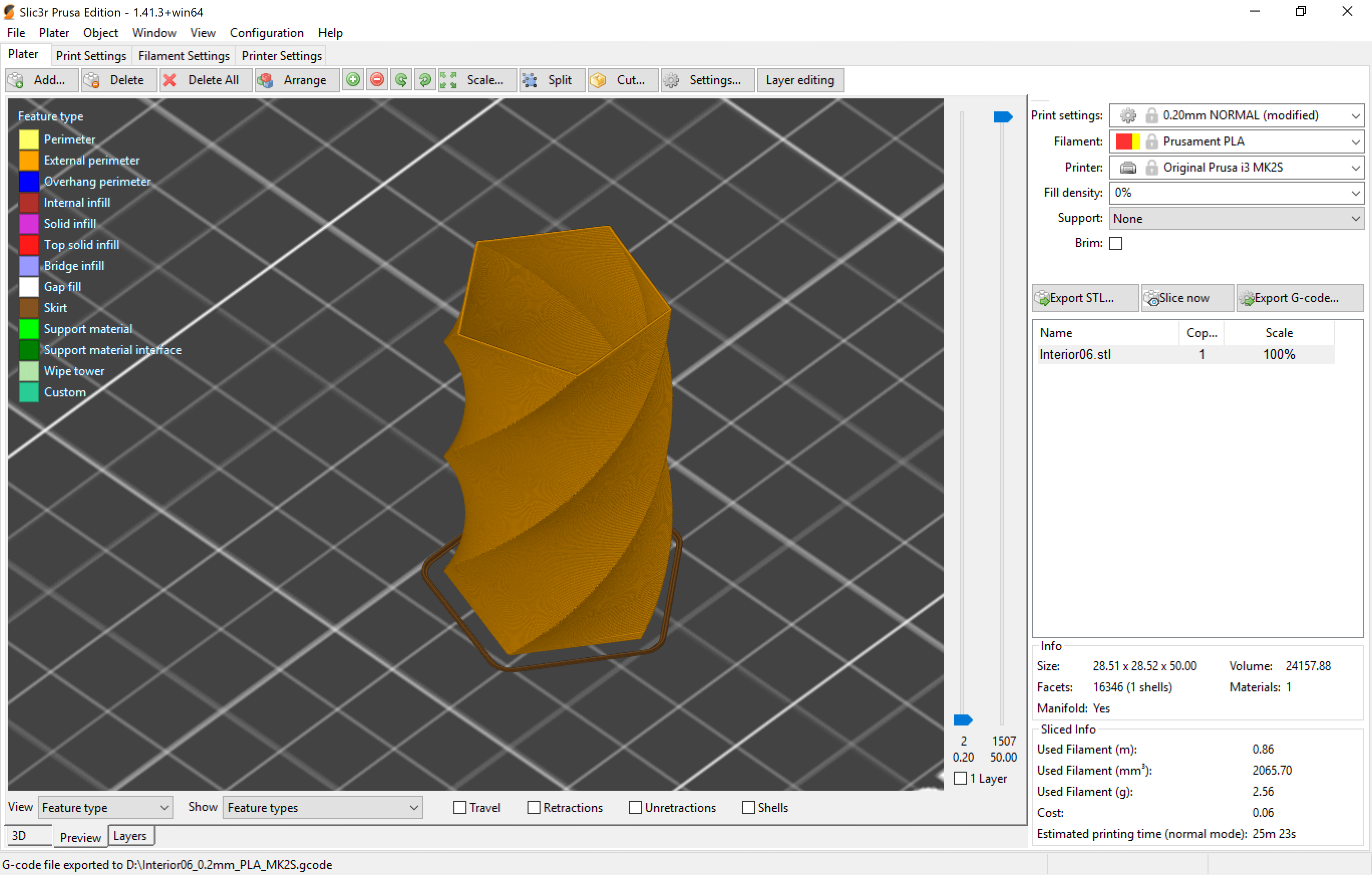
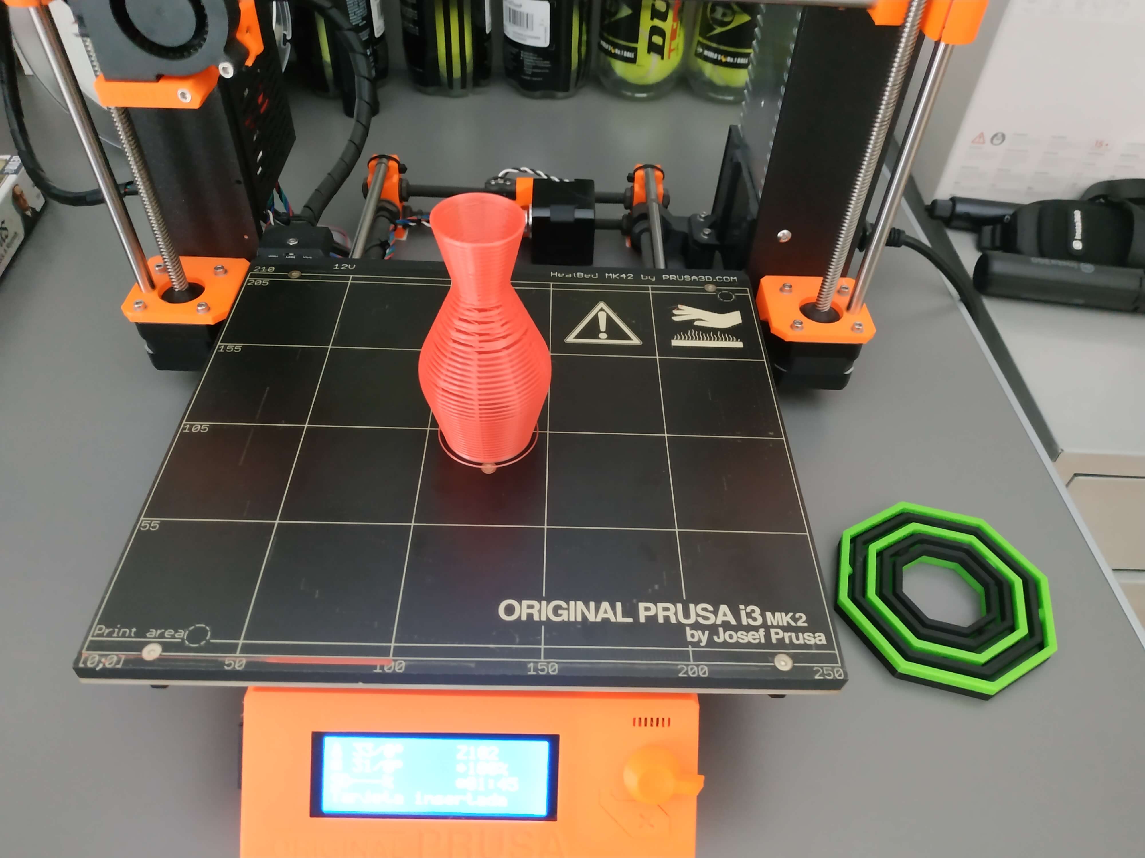
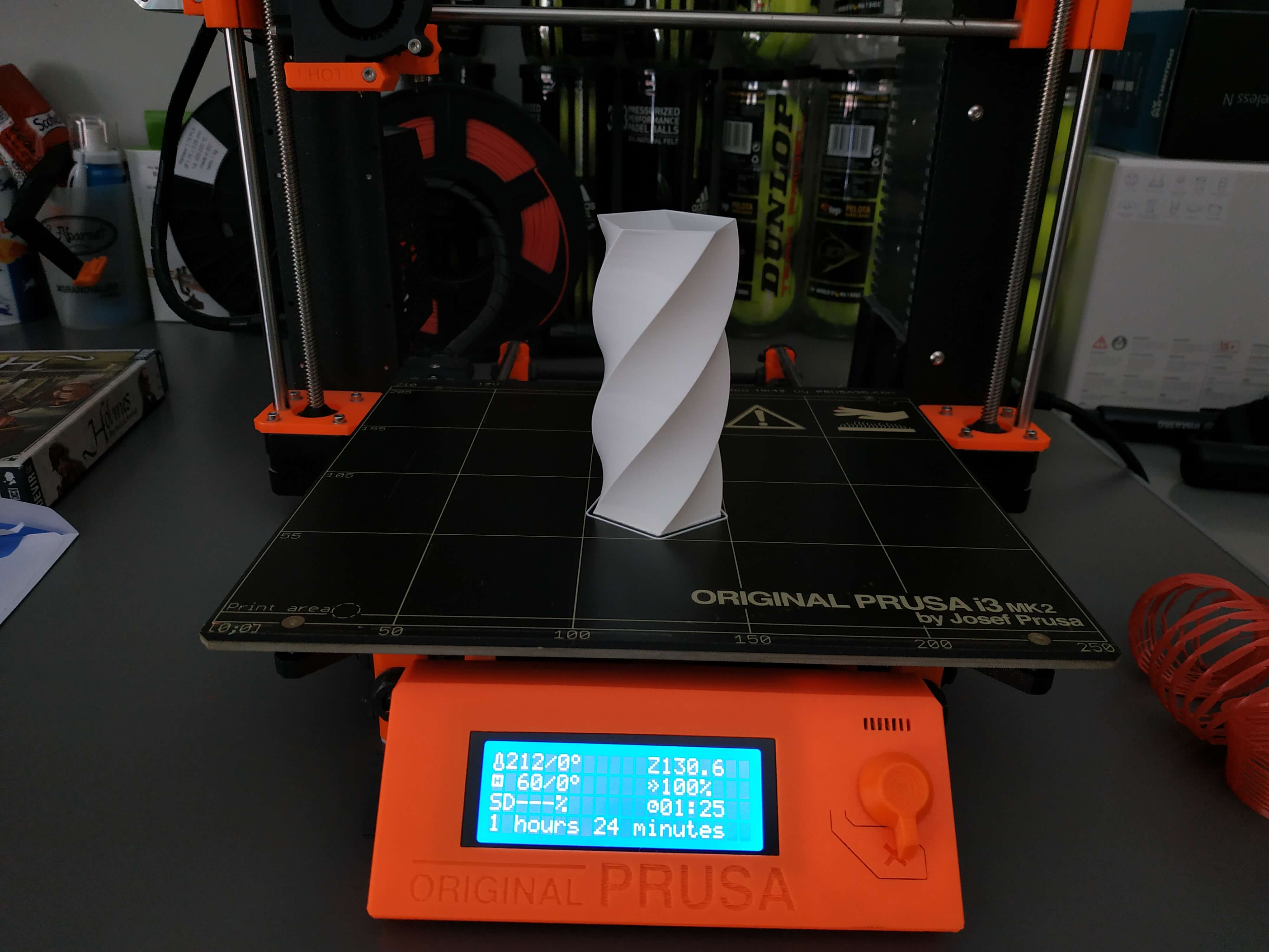
The result was really good, I did a big one first, but it took 1 hour and 24 minutes, so I decided to print a little version before printing the big one and see if the tolerance was ok. Then I print a little version, it lasted 27 minutes for each and the result was great. The tolerance was 1 mm, but I tought it could be smaller. Then I printed another one with a tolerance of 0.6 with the already printed outer part and it was more fit, so the result was not that fluent, you need more force to get it inside the other one. On the other hand, the last one had a tolerance of 0.4 with the inner part, and it doesn't fit because 0.4 is the thickness of the wall.
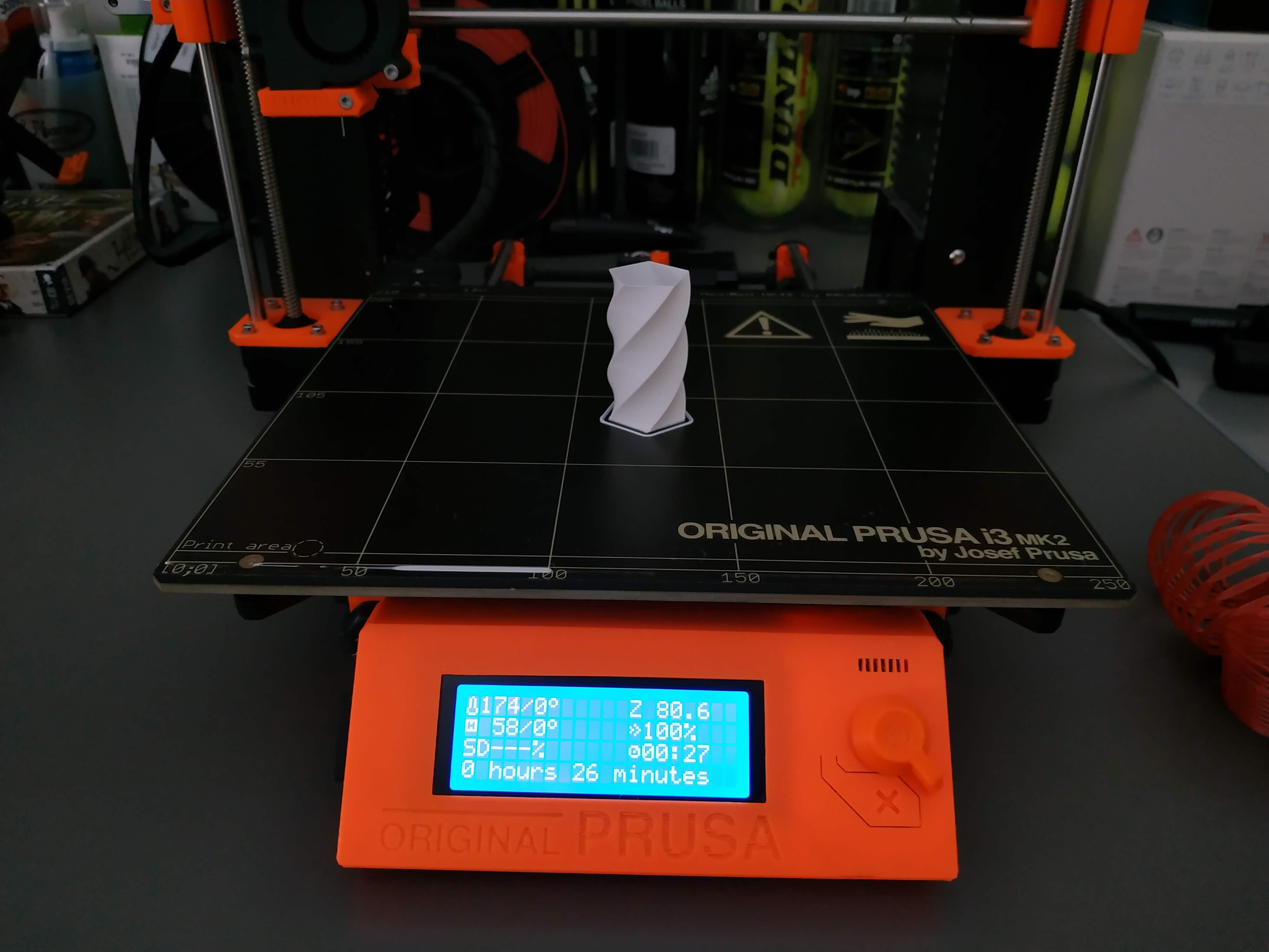
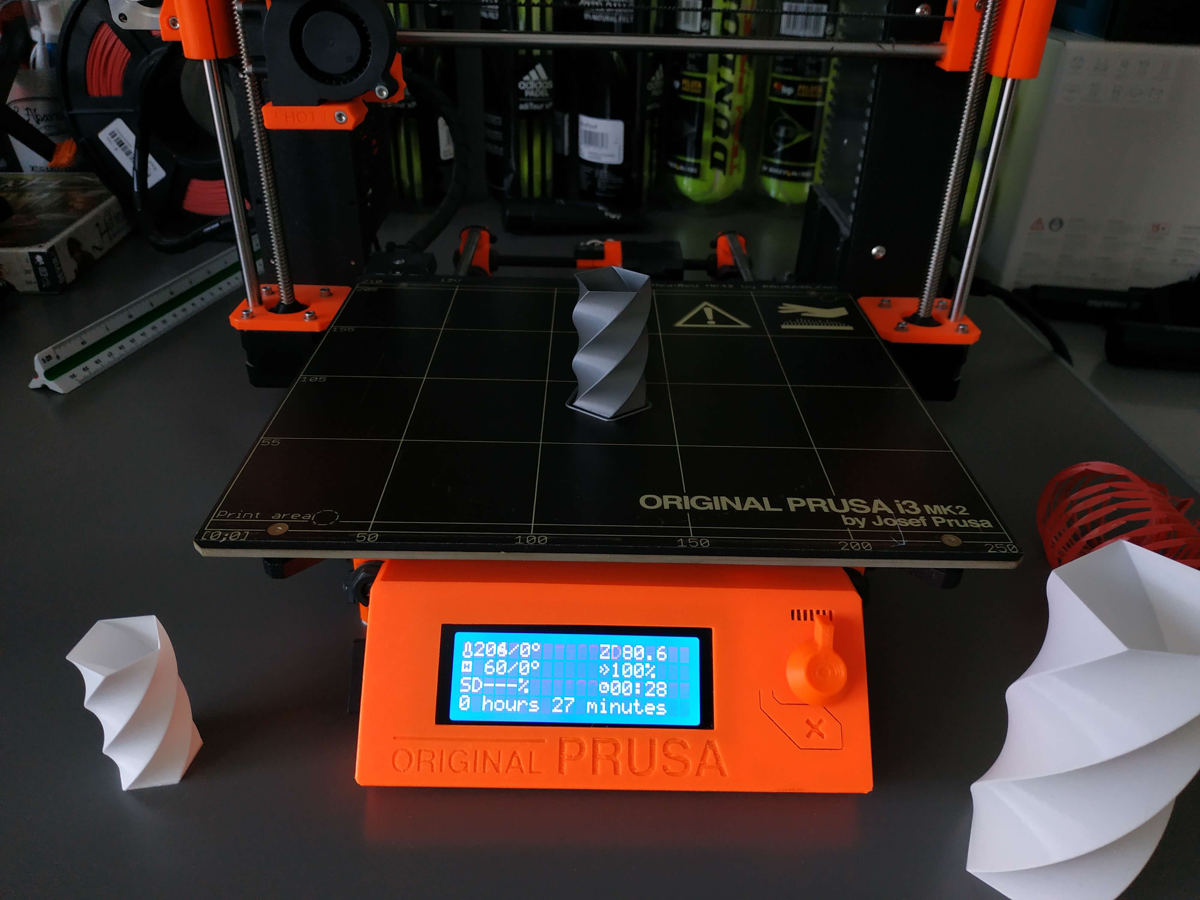
After seeing that the tolerance of 1 mm was OK, I printed the outer part of the big vase, and the result was amazing! It lasted 1 hour and 29 minutes. They fit perfectly and its amazing to asseble them.
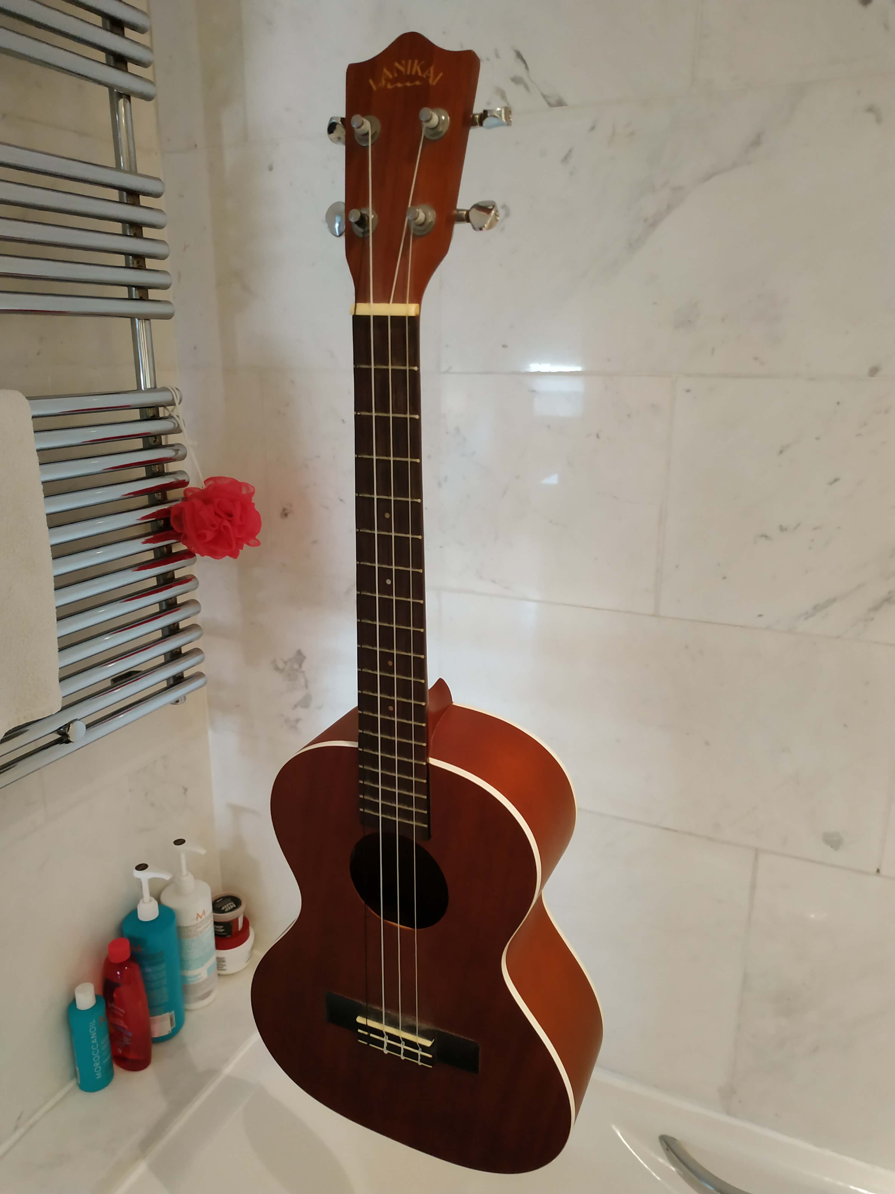
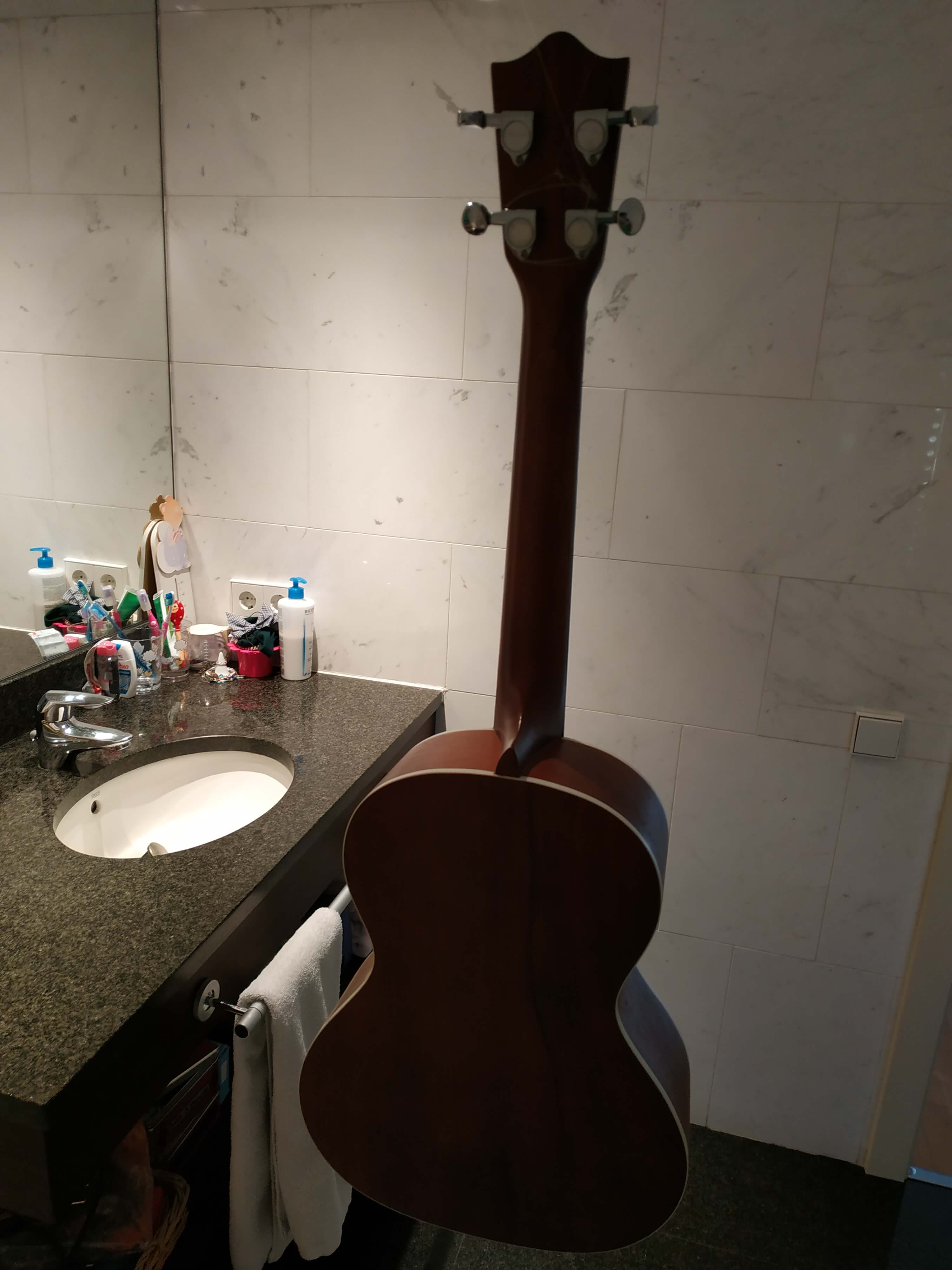
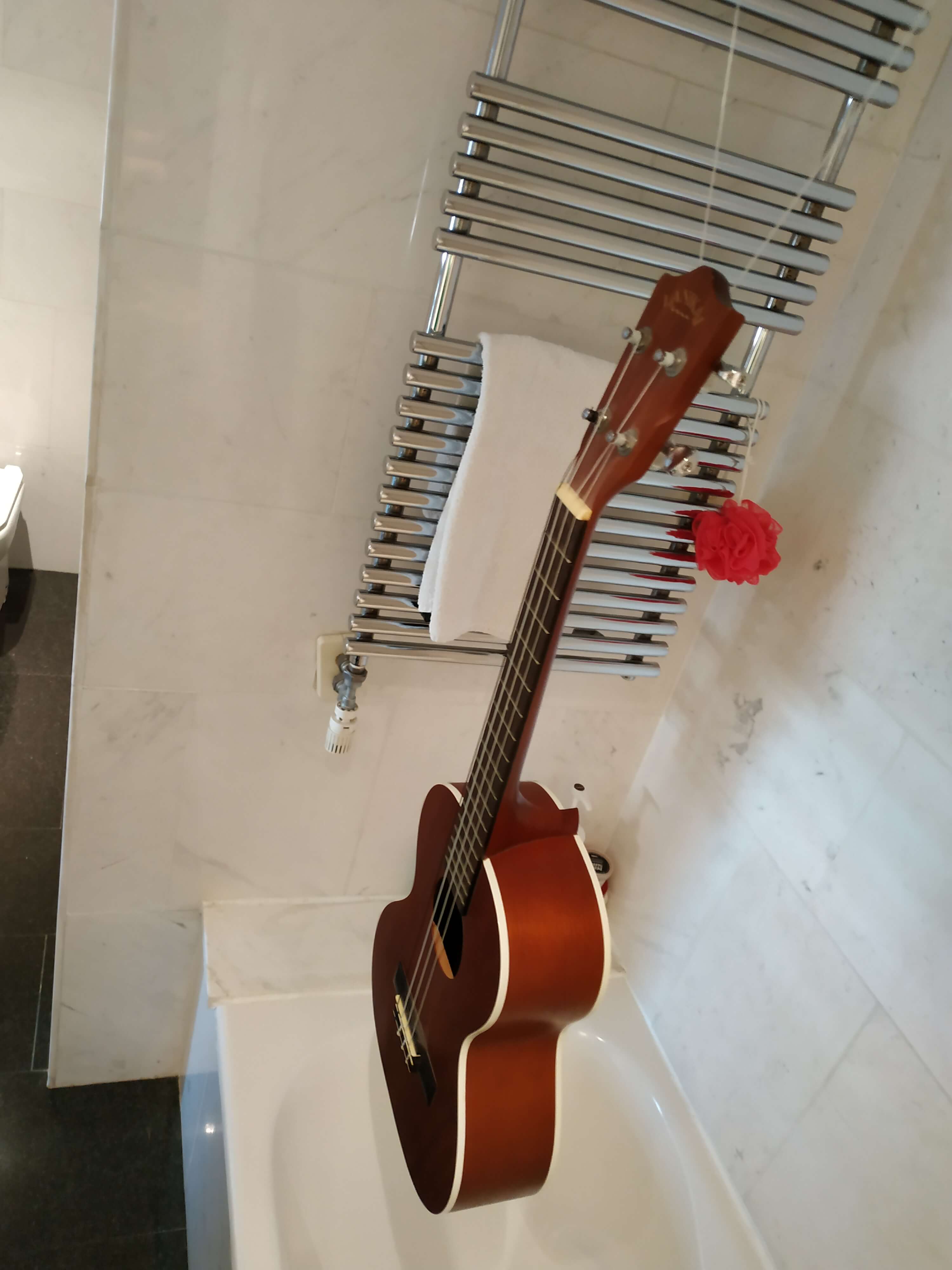
3D Scanning
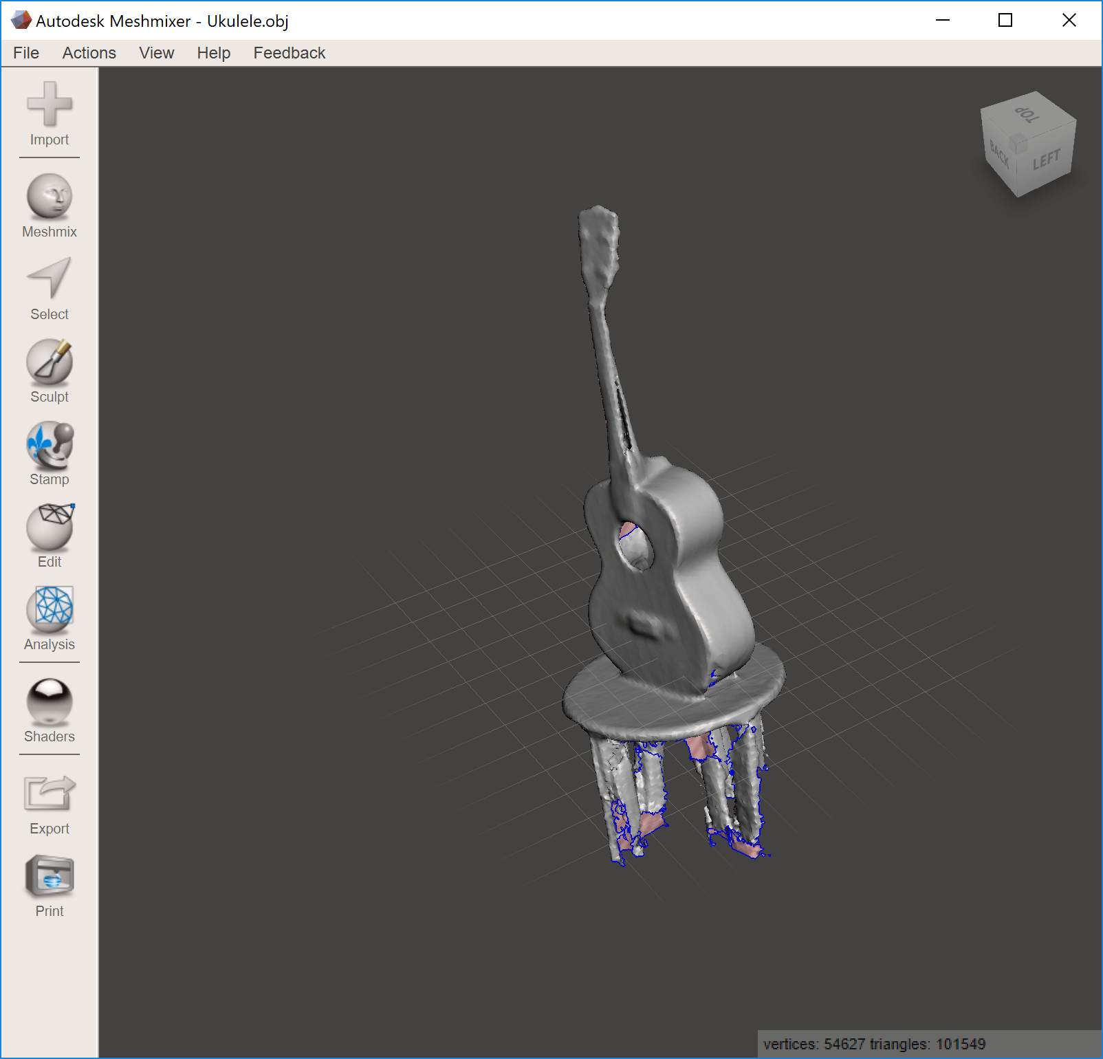
I have never done a 3D scanning before, and it has been a very nice week to learn it. To do so, I decided to scan a Ukulele for my final project, but the result was very bad, so I decided to scan myself too. I tried different softwares and ways to scan, using Autodesk ReCap to 3D scan using photogrammetry and Skanect using a Kniect. Those are the result:
Autodesk ReCap
ReCap is a photogrammetry software, that allows you to get a 3D model using a set of photos. The best thing of ReCap is that the processing of the images is done in the cloud, so your computer has not to be very powerful to get a good result. The most important thing is to make sure you get photos from all the angles, more photos will mean more quality! But you have to make sure that the photos are good, if not the result will be bad.
My intention was to 3D scan a Ukulele, so I hang my Ukulele from the shower pole with a nylon string to be able to do take pictures from all angles, get my camera out and start shooting. I did 59 photos from different positions covering all the object, but I made a big mistake... The light was really bad, so the front images and the back images were very different.
Then I used ReCap Photo to upload the pictures and send the model to the Cloud. Four hours later, approximately, the model was done, but the result was not what I expected...
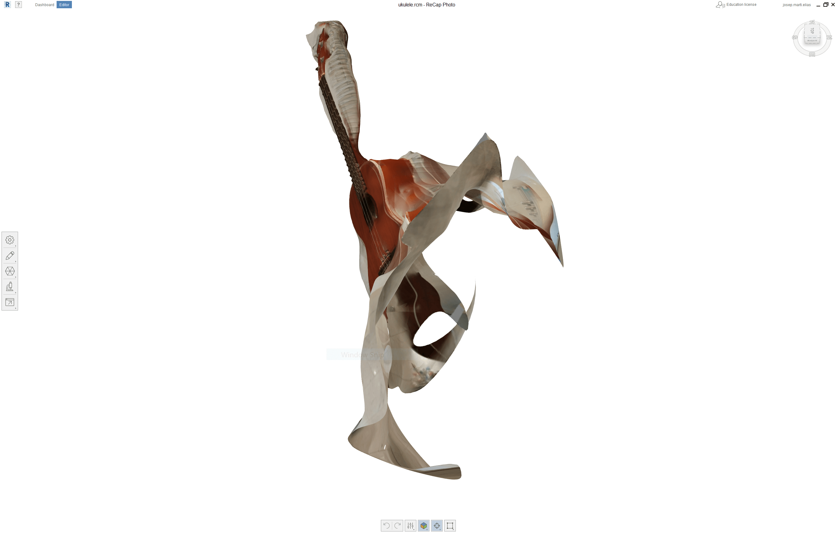
The bad quality of the images was the reason why the result was awful. I will try to scan more thing using this software, but now I want to try another process.
Skanect using a Kinect
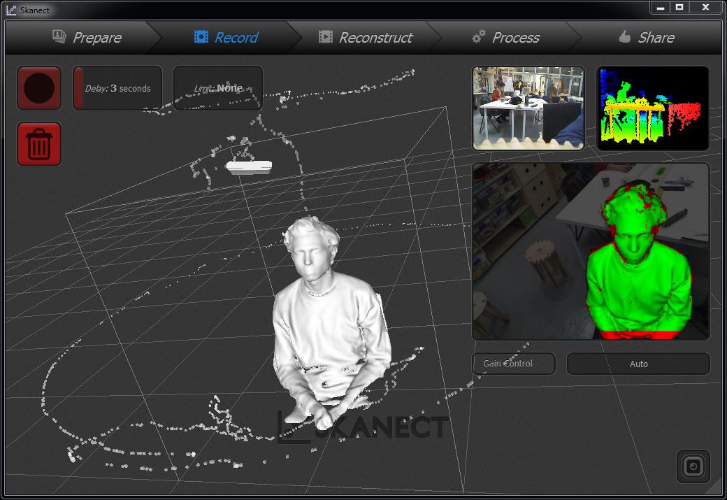
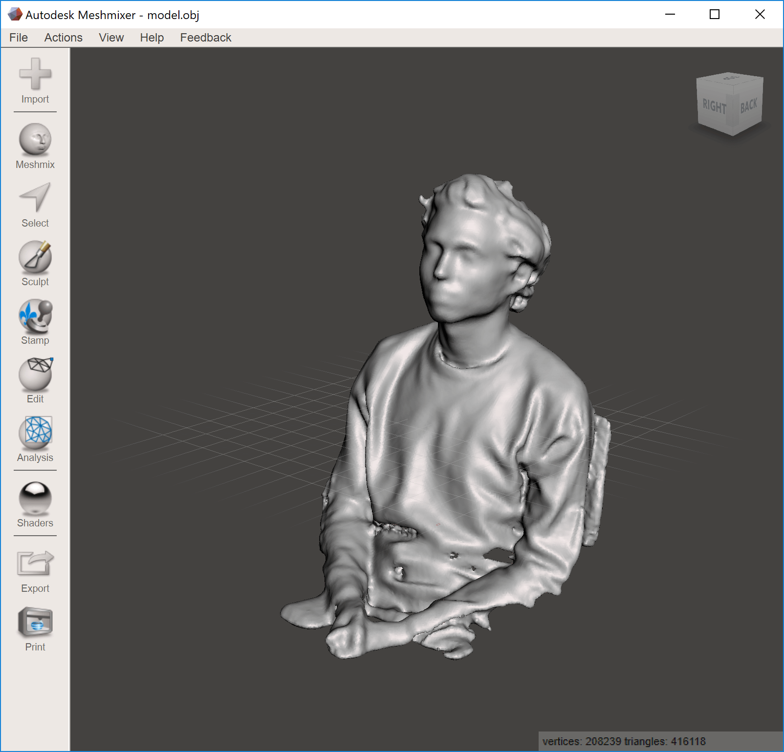
After my failure using ReCap, I decided to scan the Ukulele with a Kinect, but the result was not great either. First, let me start explaining how I used Skanect to scan myself. You can download Skanect from here.
The first thing to do is to get a Kinect and plug it into your computer. We had some issues with it because we had 2 different models of Kinect, the 1414 and 1417. In one computer, the Skanect software only recognizes the 1417 model, so we can only use one device in that computer.
Some help is needed, because you cannot scan yourself, or it is very difficult. I recommend to use a spinning chair so you can start with the Kinect placed on a table, spin slowly to get a scan, and then ask someone to grab the Kinect and finishing scanning the top and bottom parts.
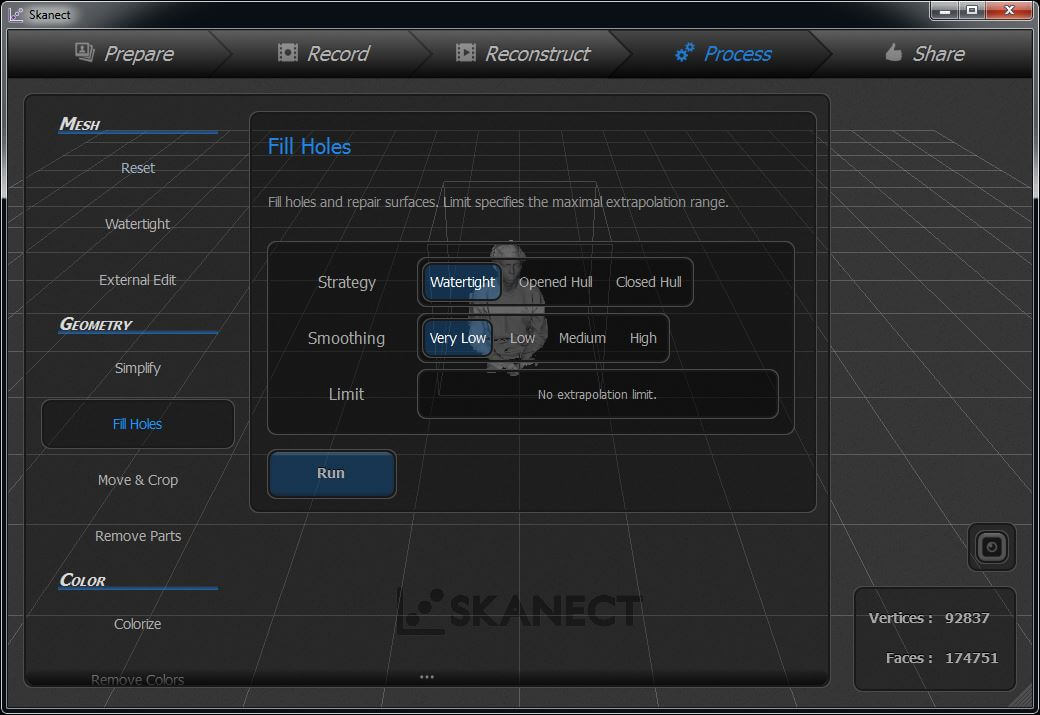
Once you finish the scan, wait for some minutes to process it, and you will see the result. There are some options for the post process of the mesh, I recommend to use the Fill Holes option, make Watertight with Low smoothing to get a good resolution.
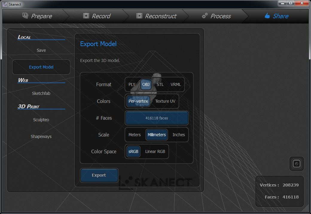
Then you can export it as STL or OBJ and import it to another software as Blender or Meshmixer to post process the mesh and fix any problem that could have appear.
The result of the scan of myself was great, but the Ukulele didn't go that well. It has some holes and the geometry is not perfect, so it won't work for me at this time. Those are the result of both scannings:
Conclusions
This week was amazing. I did have some knowledge of 3D printing, but I tried and learned new ways and methods, so now I will be able to design new things and use those features to get the best out of my 3D printer. Also, I started myself in the 3D scanning world, and I am looking forward to scan more things and get better at it.