experimentation
make it happen
Group Assignment - participants:Josep Marti, Felipe Santos, Alberto Lopez, Diar Amin, Gustavo Abreu
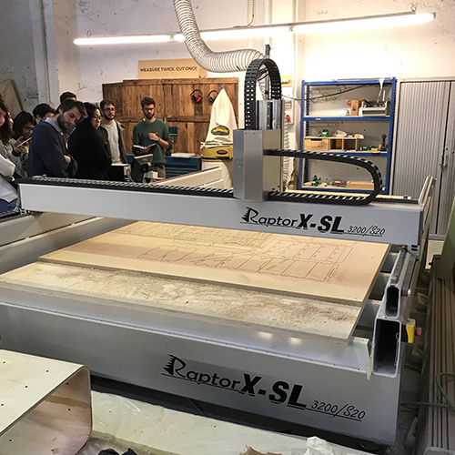
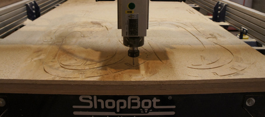
For this assignment we are using the next CNC machine: Raptor X SL 3200.
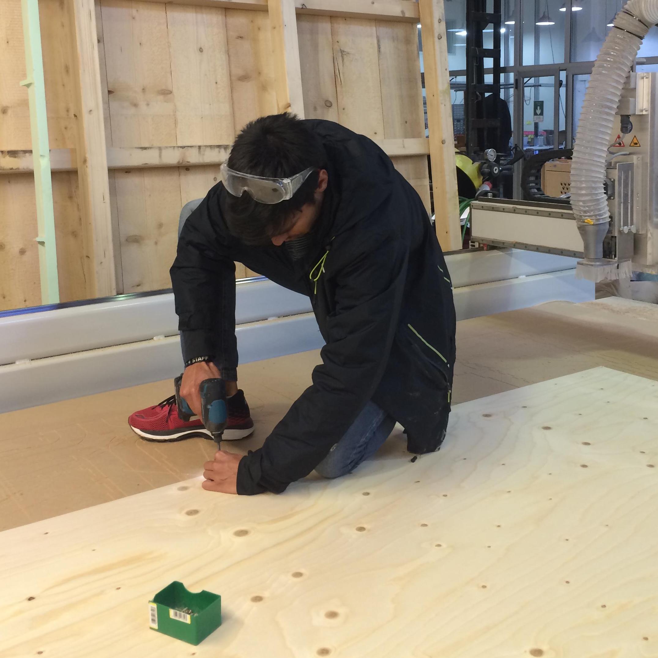
Measure and fix material.It is important to measure the full sheet from every corner. It is common to have different thickness through the material, due to fabrication or storage conditions. For instance, if the board is standing on the ground, the bottom corner may absorb humidity and be ticker.
It is important to measure the full sheet from every corner. It is common to have different thickness through the material, due to fabrication or storage conditions. For instance, if the board is standing on the ground, the bottom corner may absorb humidity and be ticker.

Remember the 0 is set to the bottom left corner
Install end mill
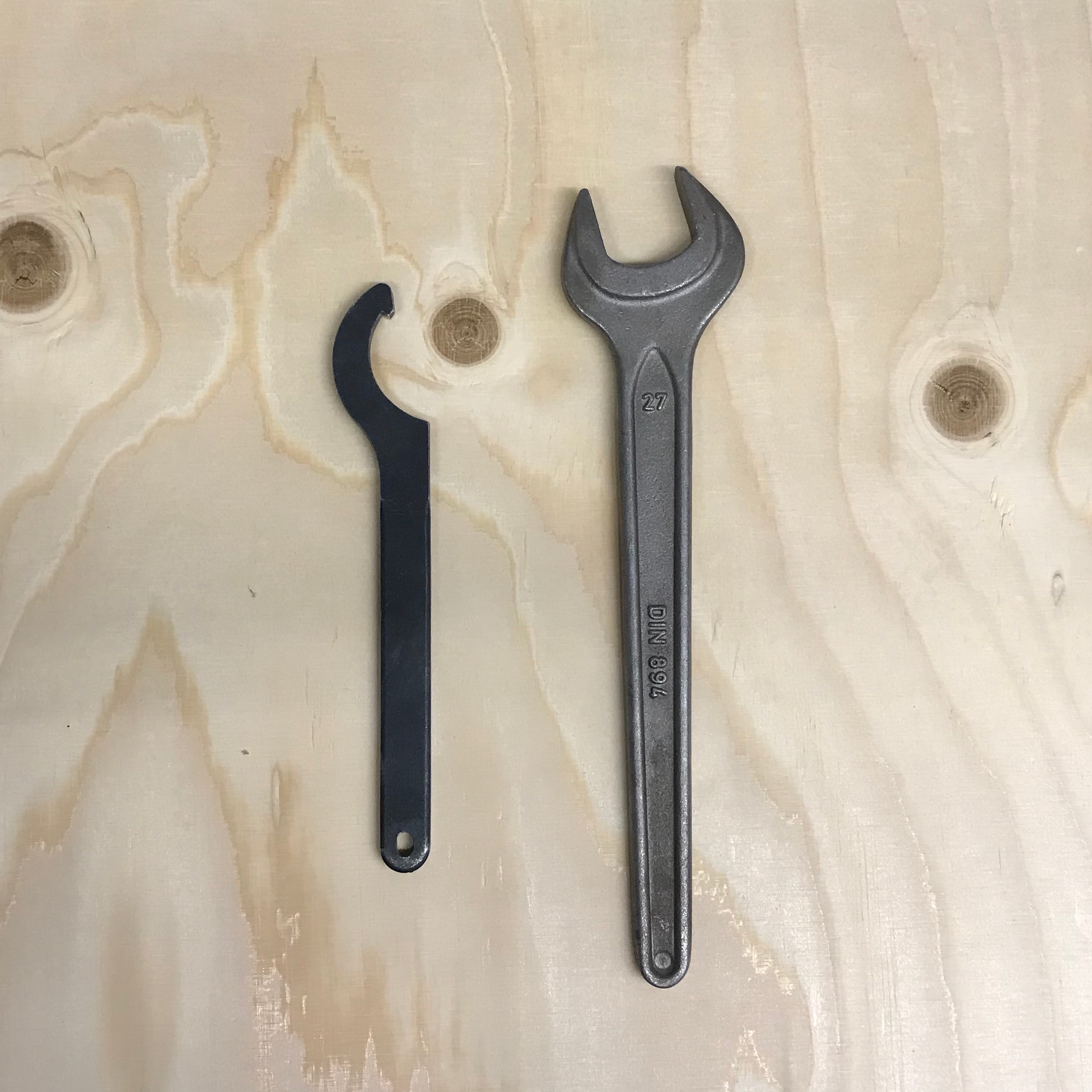
If necessary, you can remove the dust collector to make it easier to change the tool. Use the machine’s wrench and key to release the collet and holder.
For safety, don’t hold it from the flutes. You can easily cut yourself. It is recommended to hold the shank instead. A little trick to get the collet out of the holder is to press it laterally. You should leave around 2-3mm of the shank out of the collet and then tighten with the wrench.
Set each axis origin. If you placed the board aligned with the machine bed, X,Y could be set by sending it to home, if not, move then to the origin of your board and set the 0 there.
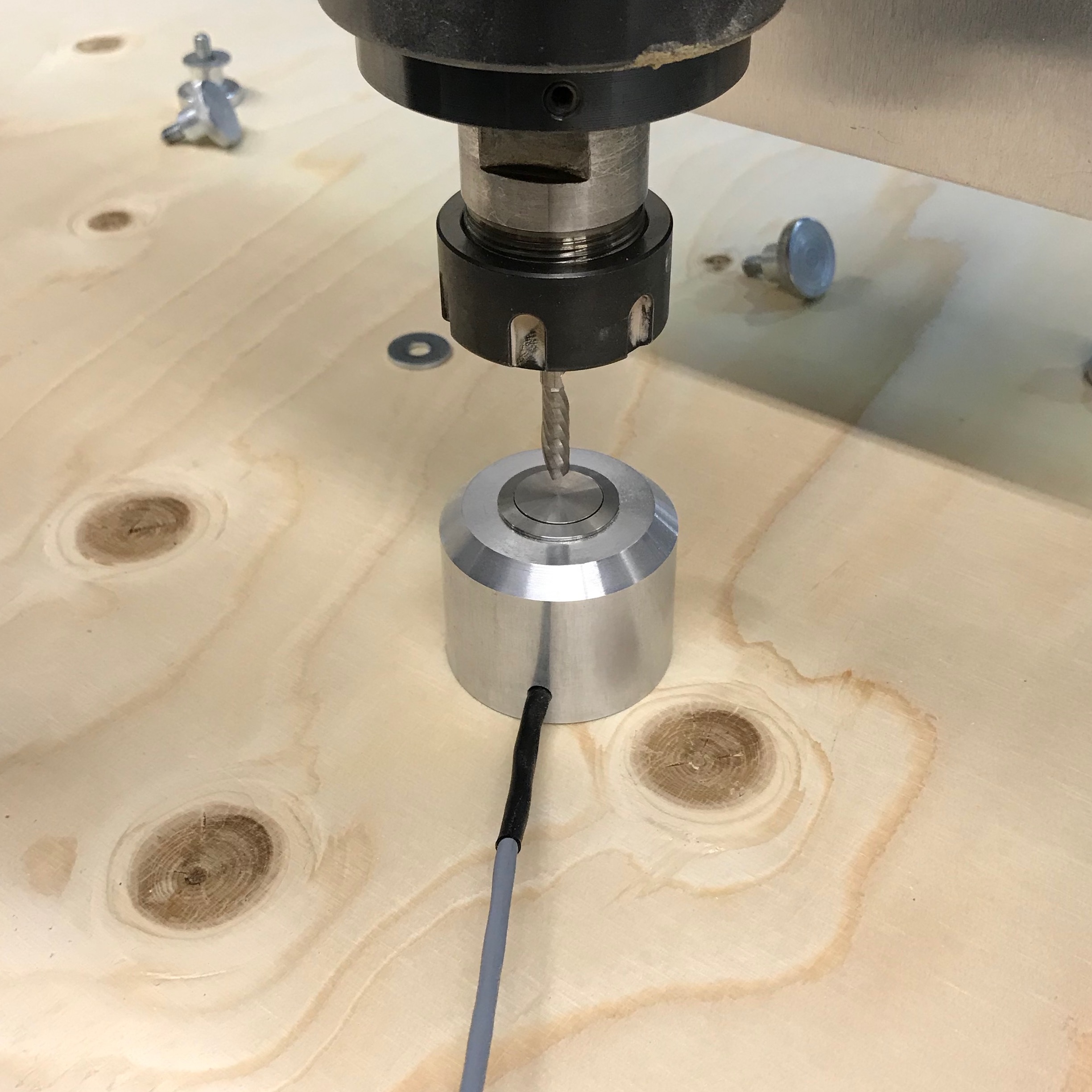
To set Z, we have the auto-leveler, that should be set right under the tool.
Start job
After doing all that, is time to start the machine, but first, a couple of checks:
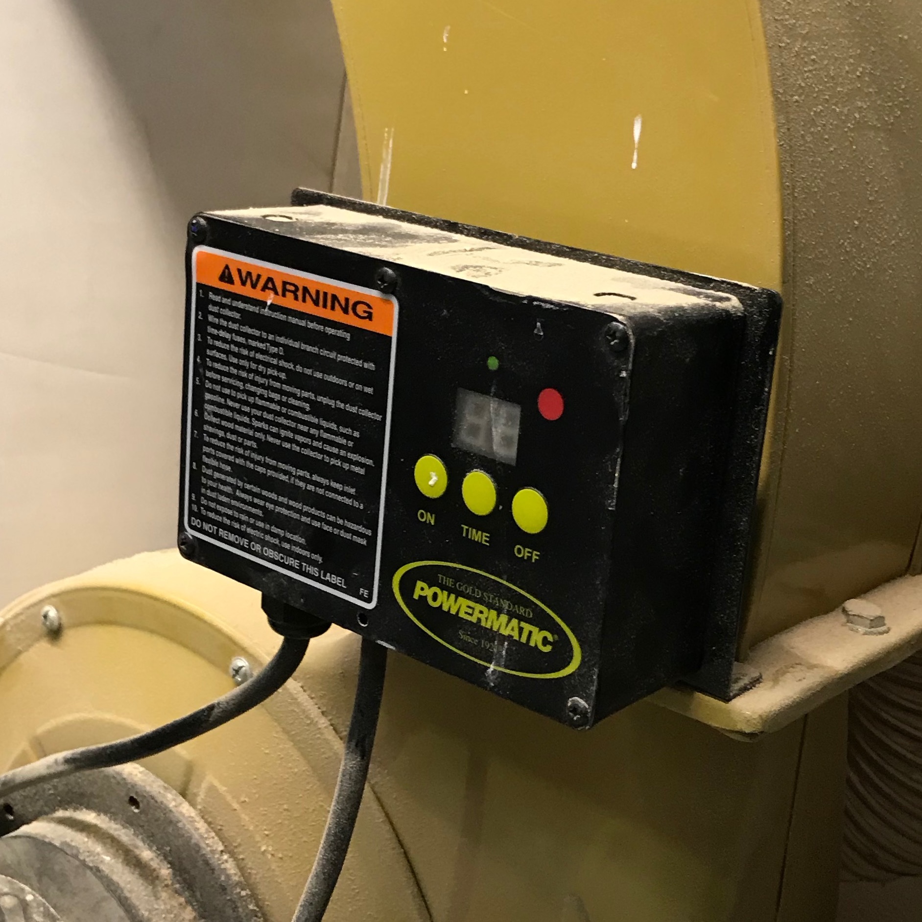
Make sure dust collector is on.
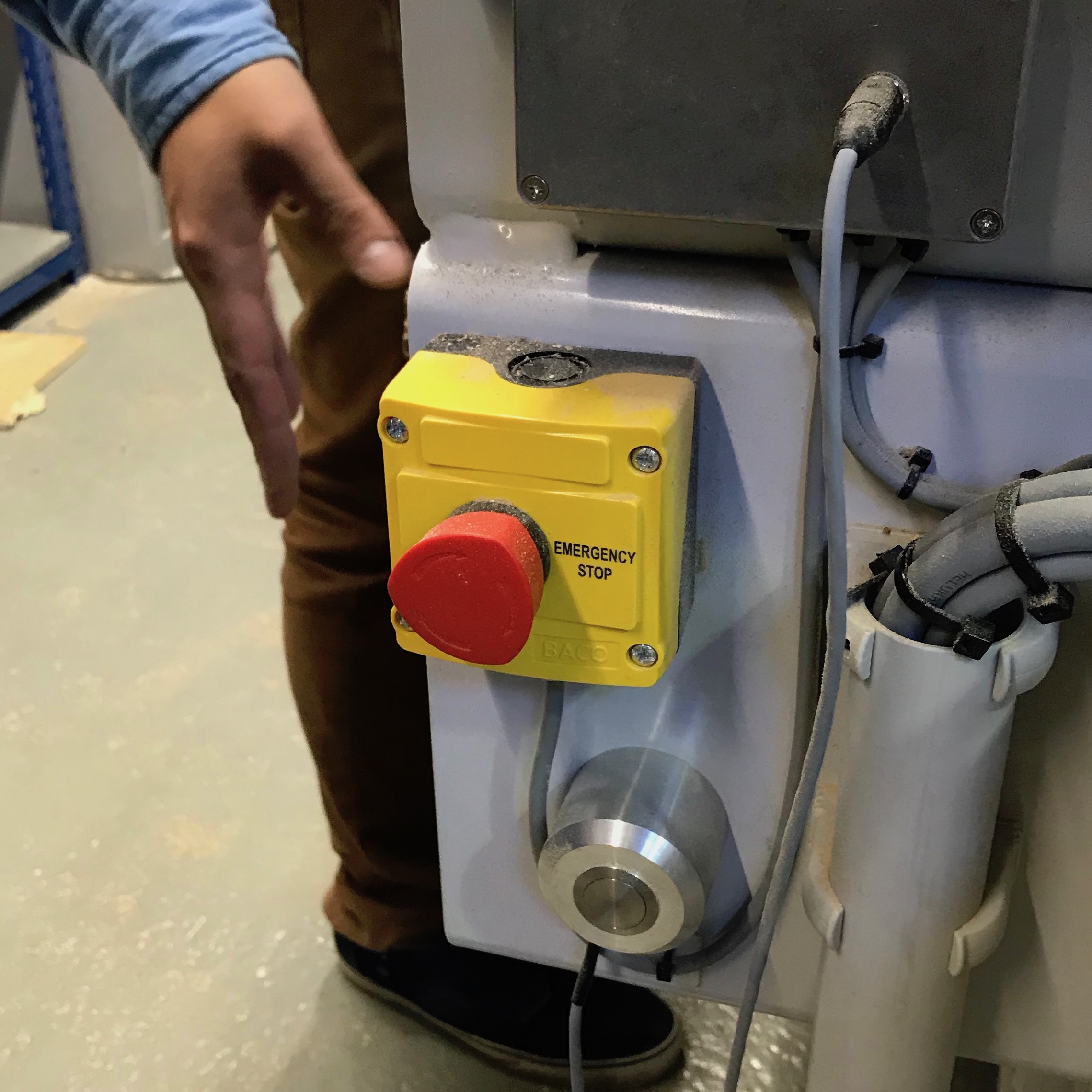
Make sure you know where the emergency button is.
Wear safety glasses, closed shoes and earmuffs. Only then, start the job.
Finish job
After finishing, move the axis away so you can reach the cutout pieces, turn off the machine and dust collector, only then proceed to remove the material. Remembering to clean after yourself and store all the tools and protection gear.
Chip load Calculation. also can be calculated here: https://pub.pages.cba.mit.edu/feed_speeds/
A really basic calculation is to multiply the spindle RPM x number of flutes X chip load, to get the appropriate feed rate. We got 2440x1220 15mm spruce plywood boards. After a quick search, we found that the chip load is between .011”-.013”. Since our machine is set up in millimeters, we did the following calculations 18k x 1 x 0.28 5040 20k x 1 x 0.28 5600 22k x 1 x 0.28 6160 24k x 1 x 0.28 6720
Tests
Even tough we had the numbers, we wanted to try the possible combinations, varying from 18k RPM with 2k feed rate, up to 24k RPM with 7000 feed rate. But, the math does not lie. The best results were the ones we previously calculated. This are the results with a downcut end mill.

We repeated the test with a up cut as well and got batter results. But probably the main reason is because the tool was newer and more sharp.
Individual Assignment:
At first, it is important to understand the difference between 2D, 2.5D and 3D contouring. Neil also was talking about it in his lecture, but just to sum up, working in 2D means that you are cutting out a part with features that are all at the same depth. Working in 2.5D means you are cutting a part that has multiple flat features at varying depths. During a 2.5 D cutting process, the Z-axis positions itself to a depth where the X and Y axes interpolate to cut a feature. The Z axis then retracts so the X and Y axes can move to the start point of the next feature, which may be cut at a different Z depth than the last feature. When working in 3D - contouring can then be accomplished by creating curves that use all three axes at once.
#design
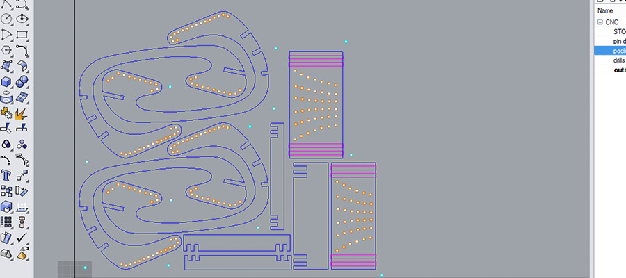
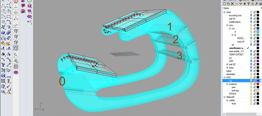
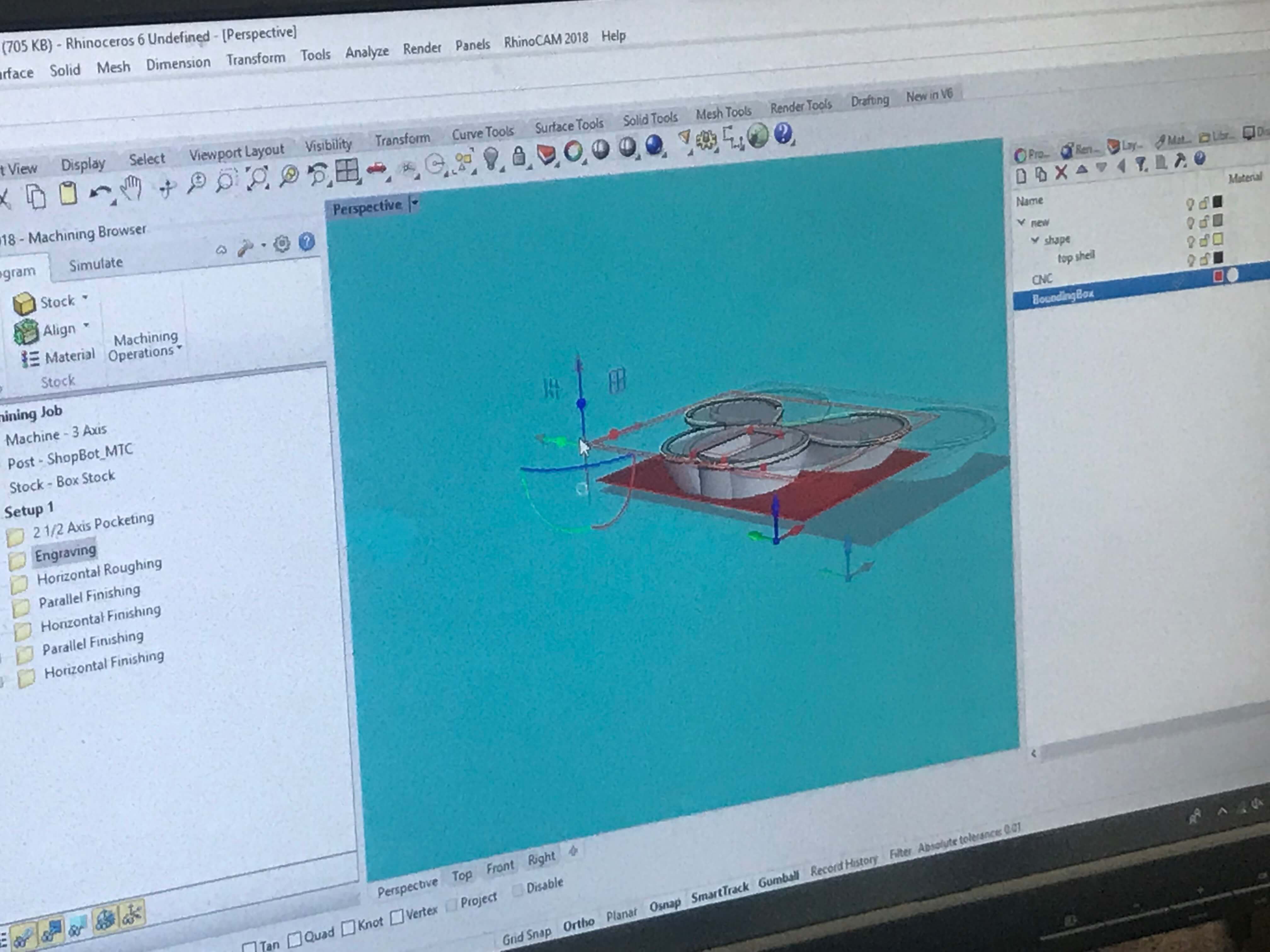
#layout for CNC cutting. Workflow 1. Open Rhino CAM 2. Defining the Bounding box strategy 3. Defining Pins downs strategy 4. Defining Inside profiling 5. Defining Pocketing strategy 6. Defining Drilling strategy 7. Defining Outside profiling strategy...this is what needs to be done in future steps...
#layout for CNC cutting in Rhino CAM. is needed to setup the right machining processes with the right tools. export files and take them to the computer connected to the machine.
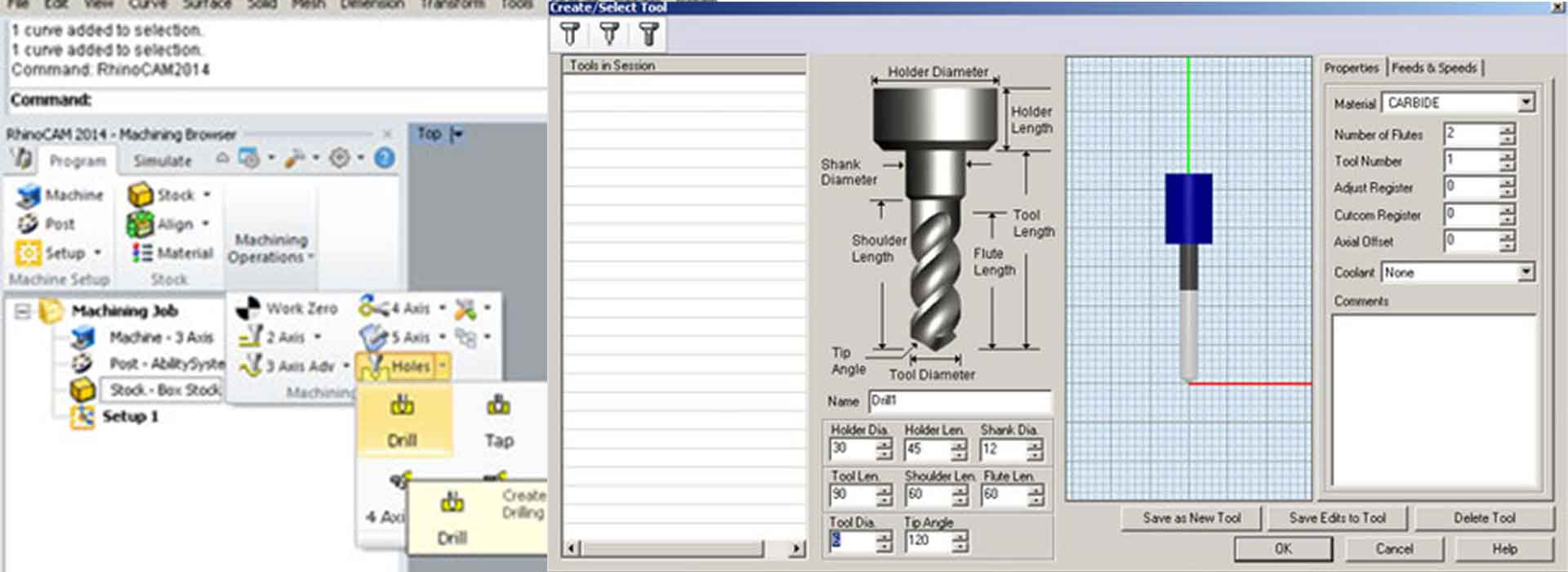
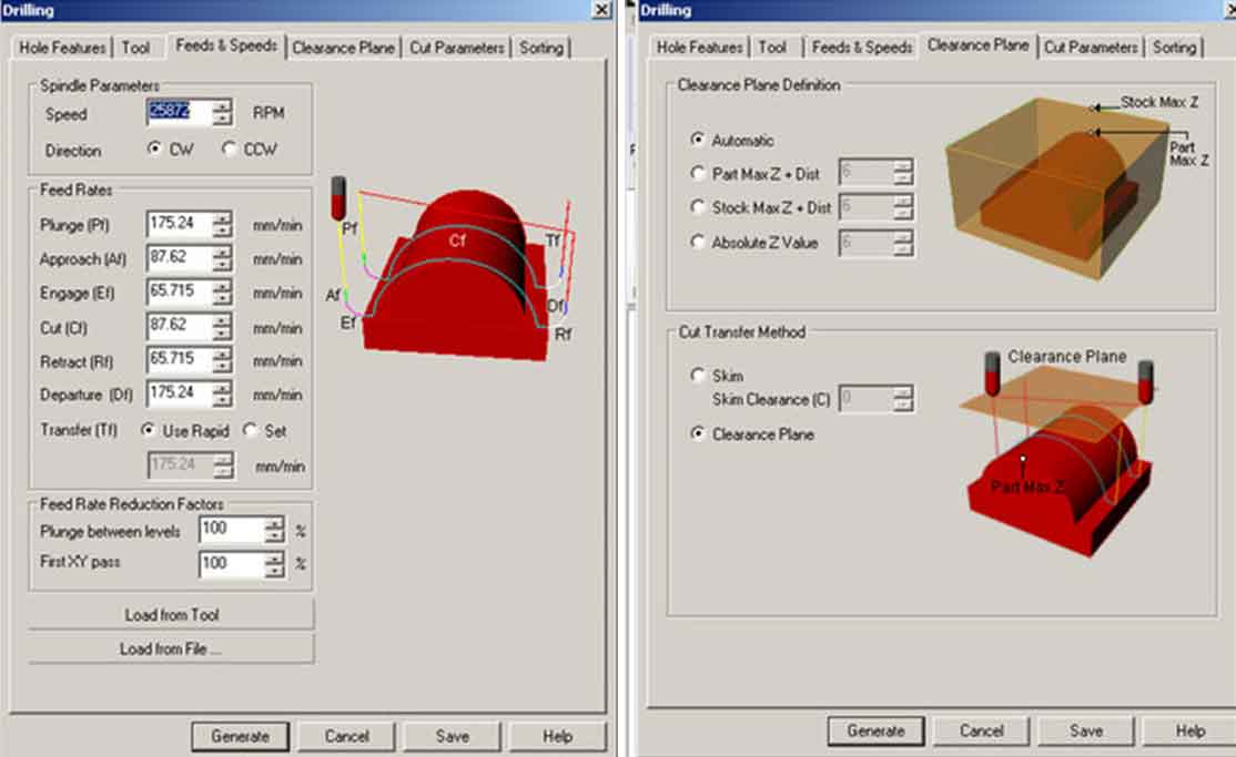
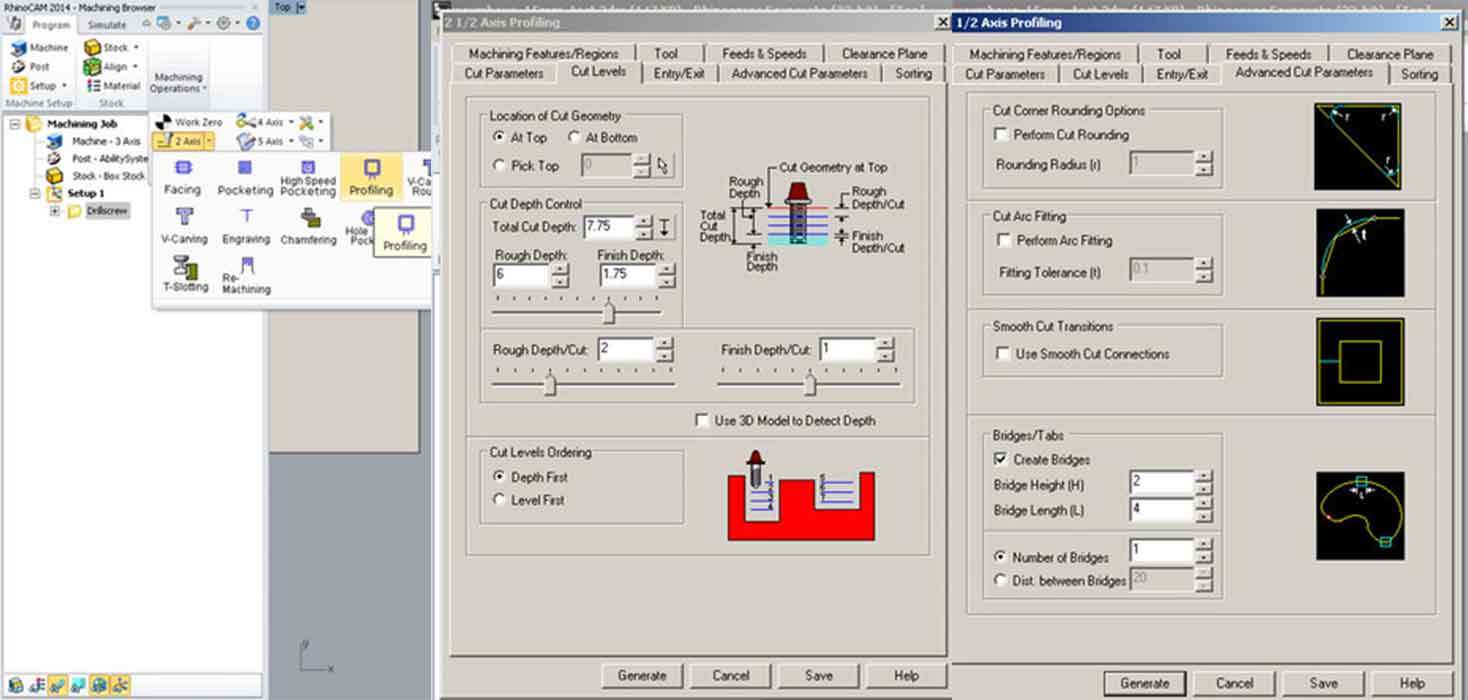
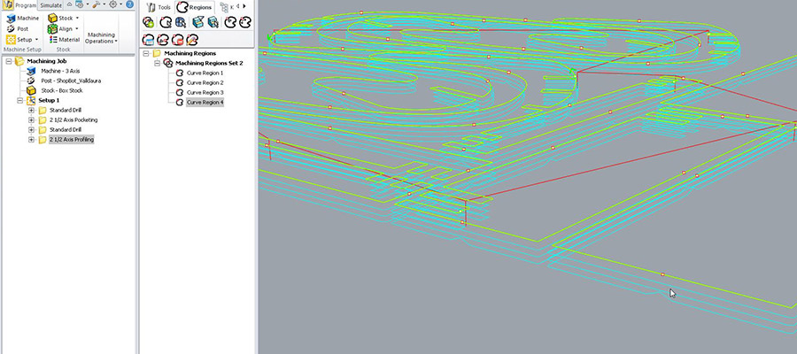
For generating code in RhinoCAM: Go to Machine operation, Select 2 axis, Select your type of strategies for your layer, Select reference "select drill points // Select drill points & circle...Select tool / drill bit / 6 mm Check Speed // Check sense of mill bit Clock-wise // Change the speed to 20 000...see the screenshots for more settings to follow... Press "Generate"...Then Go to Machine operation // Select 2 axis // Select Profiling ...next step is making pocketing. For Pocketing layer Go to Machine operation Select 2 axis Select your type of strategies for your layer > "pocketing" Select "control geometry" / remove all Go on your "pocketing layers" and "select objects" layer / press OK Select your tool > Edit / Create / Sellect tool: Check Speed Check sense of mill bit Clock-wise. Cut parameters Total cut depth=7.75 Rough depth = 6 Rough depth cut= 2 (to indicate that we will do 3 rounds) Finish depth=1.75 (to finish Finish depth cut= 1.75 (to indicate that we will do 2 rounds) Press "Generate"
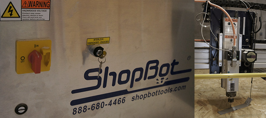
#switch on the machine and setup origin
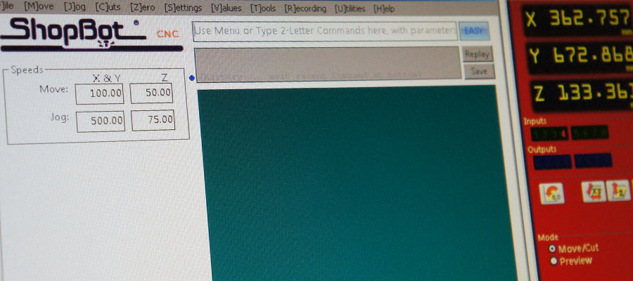
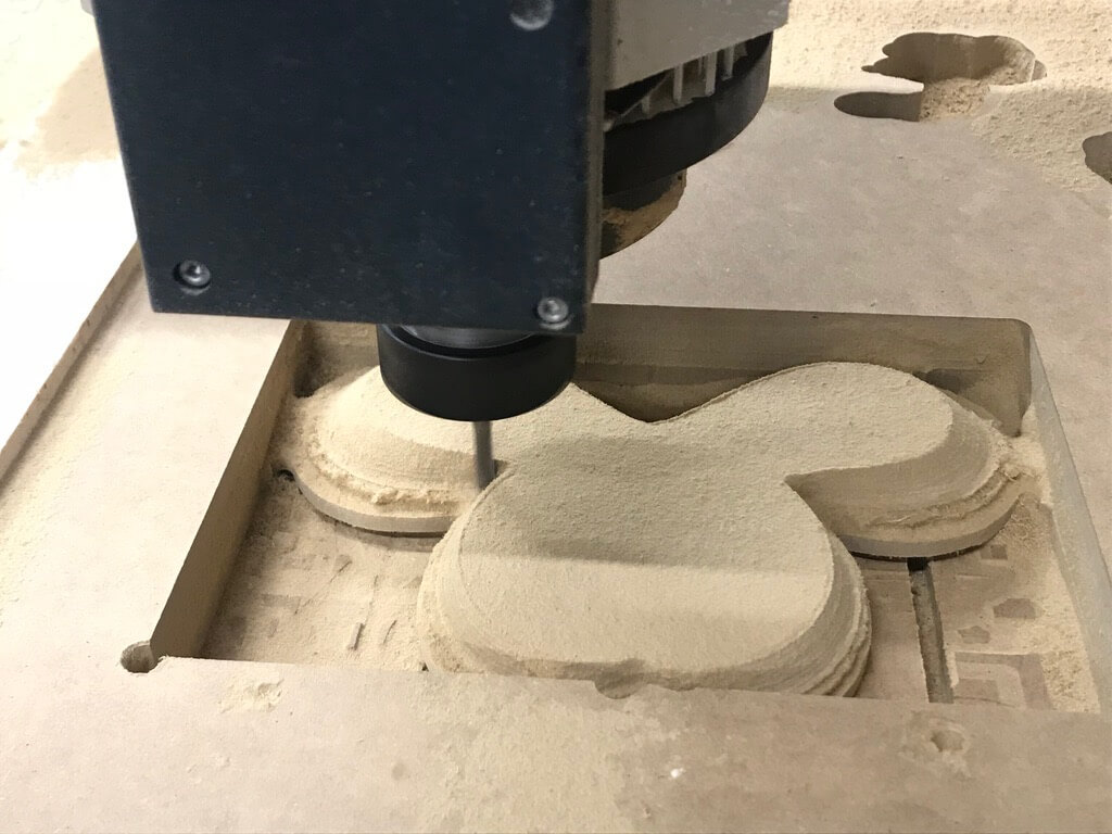
#start processing
#watch out the machine while processing cutting. when there is too much substracted material, clean it!
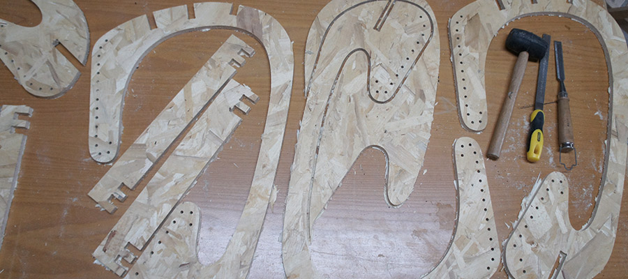
#ready cutted parts. we can see that it didnt cut it properly, so it was needed to use additional tools as you can see on the picture to remove and clean components.
Video of the process of CNC production. This was happening in the Green Fab Lab Valldaura in March 2016 and I got the assistance from the lab lead Johnatan with the machine processing.

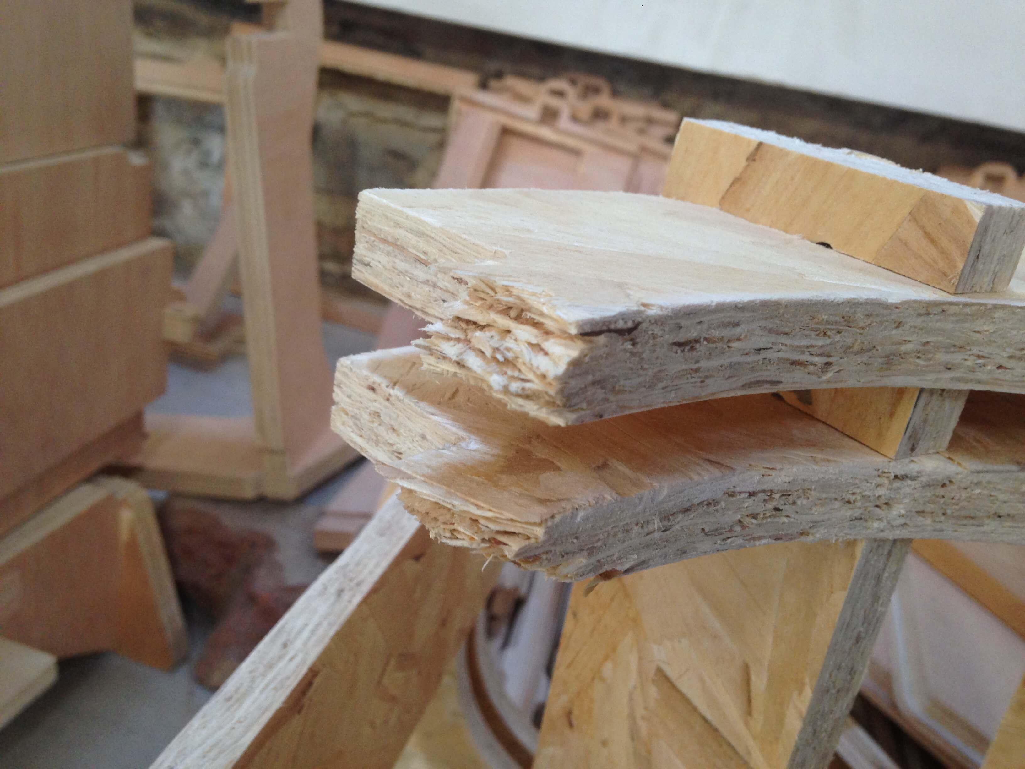
As you can see, it broke when I wanted to test it. joining parts were too thin and the material was not really proper for such a thin connections. what we realized after.so for the future improvements is good to focus on better joints ;)
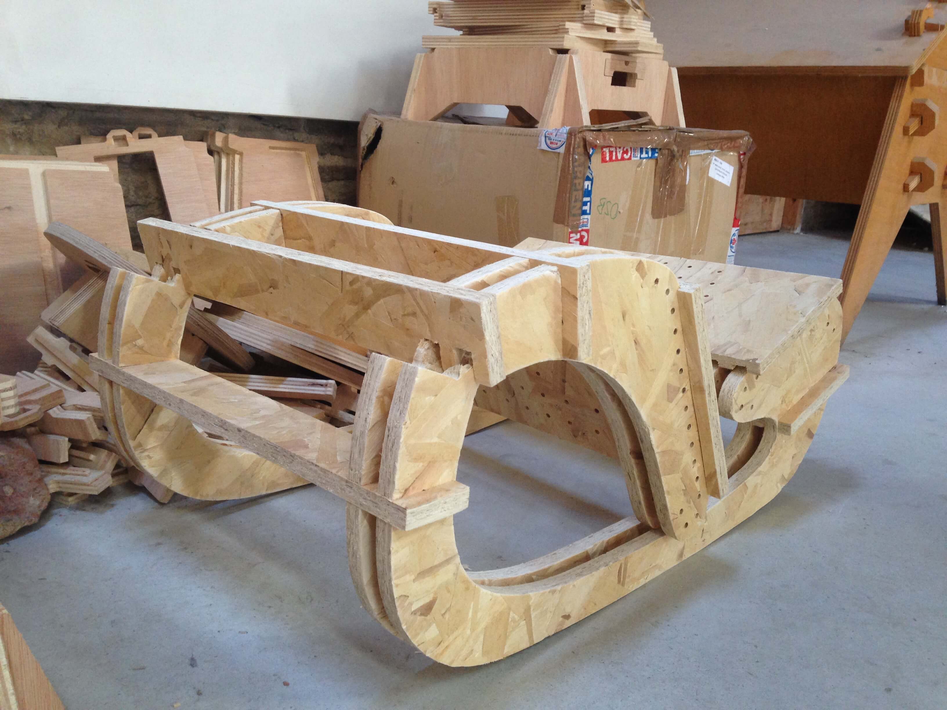
and since I was doing this back in 2016 I couldnt recover the files. I made the CAM files in Valdaura PC and so the files are gone. anyway I decided to make CNC for my final project. The idea was to make a base for my lamp using subtractive machining technique. For prototype I was using lasercutting, now I wanted to do the final version of my lamp using CNC milling.
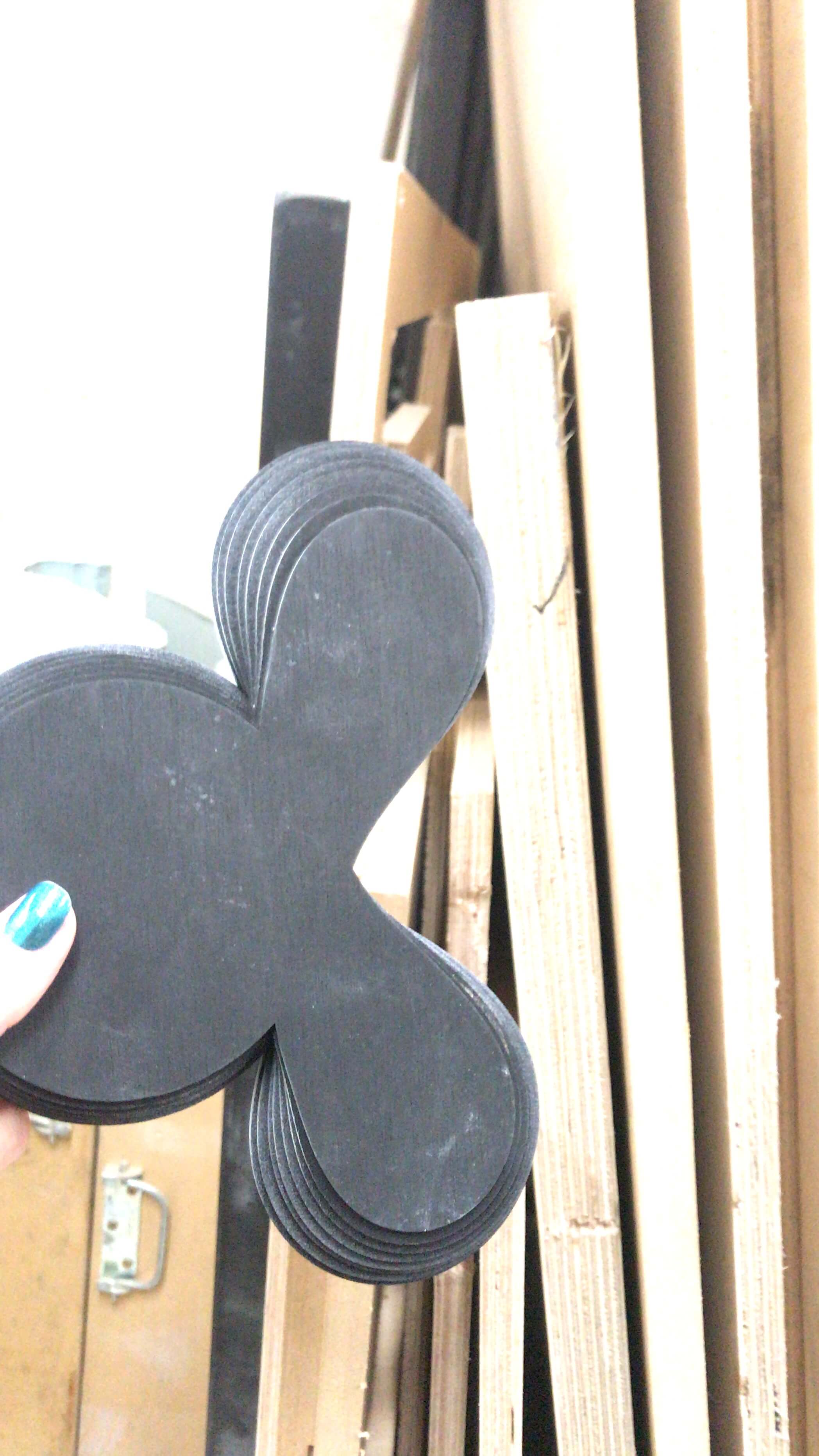
#transformation from this laser cutted prototype to wished milled piece.

#fixing the material to the machines cutting bed with drilling screws and also wooden pieces to follow the right alighnment when there will be the time to switch to the other side.
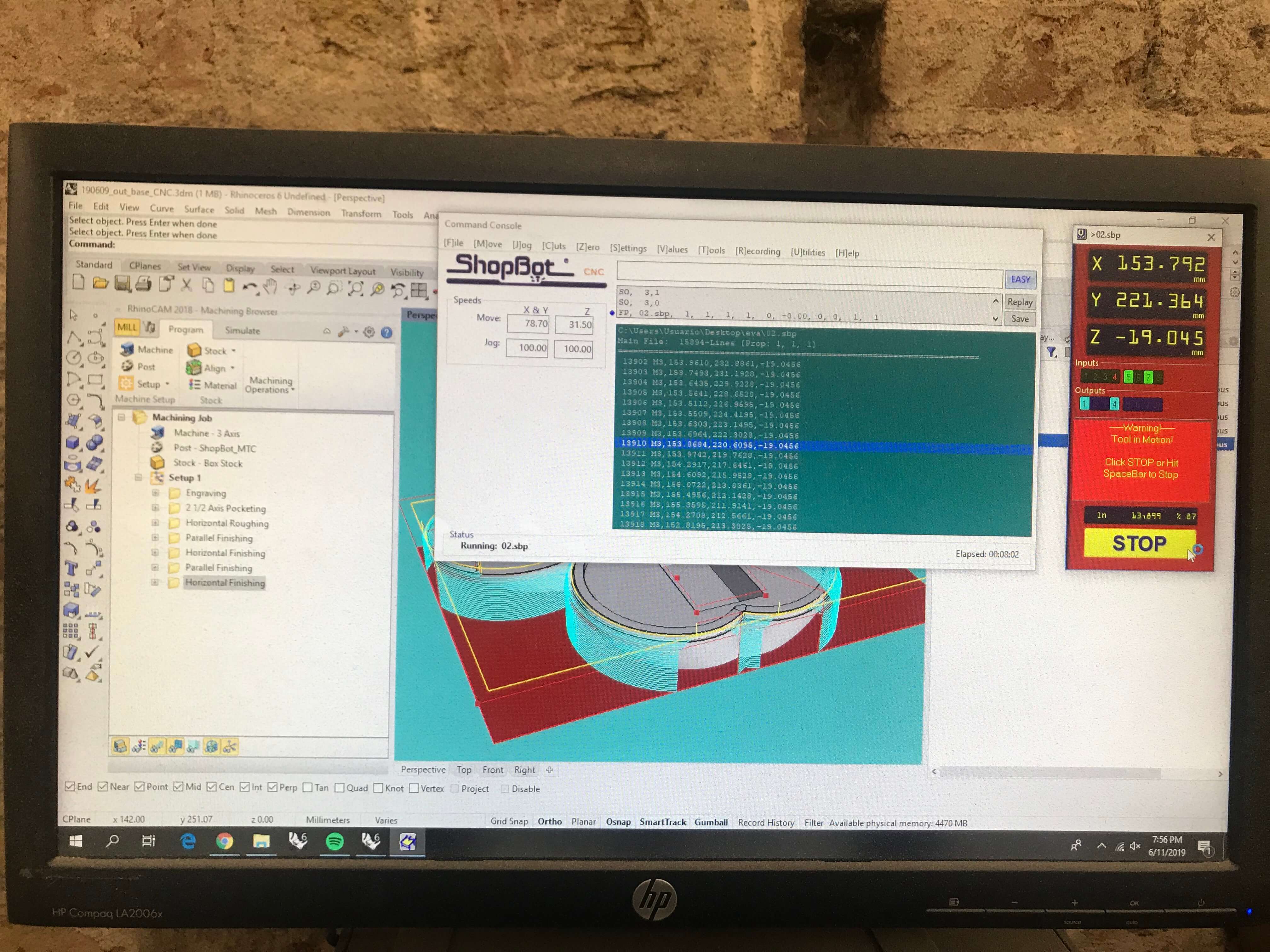
#setting up the right machine processing in the lab computer in RhinoCAM.
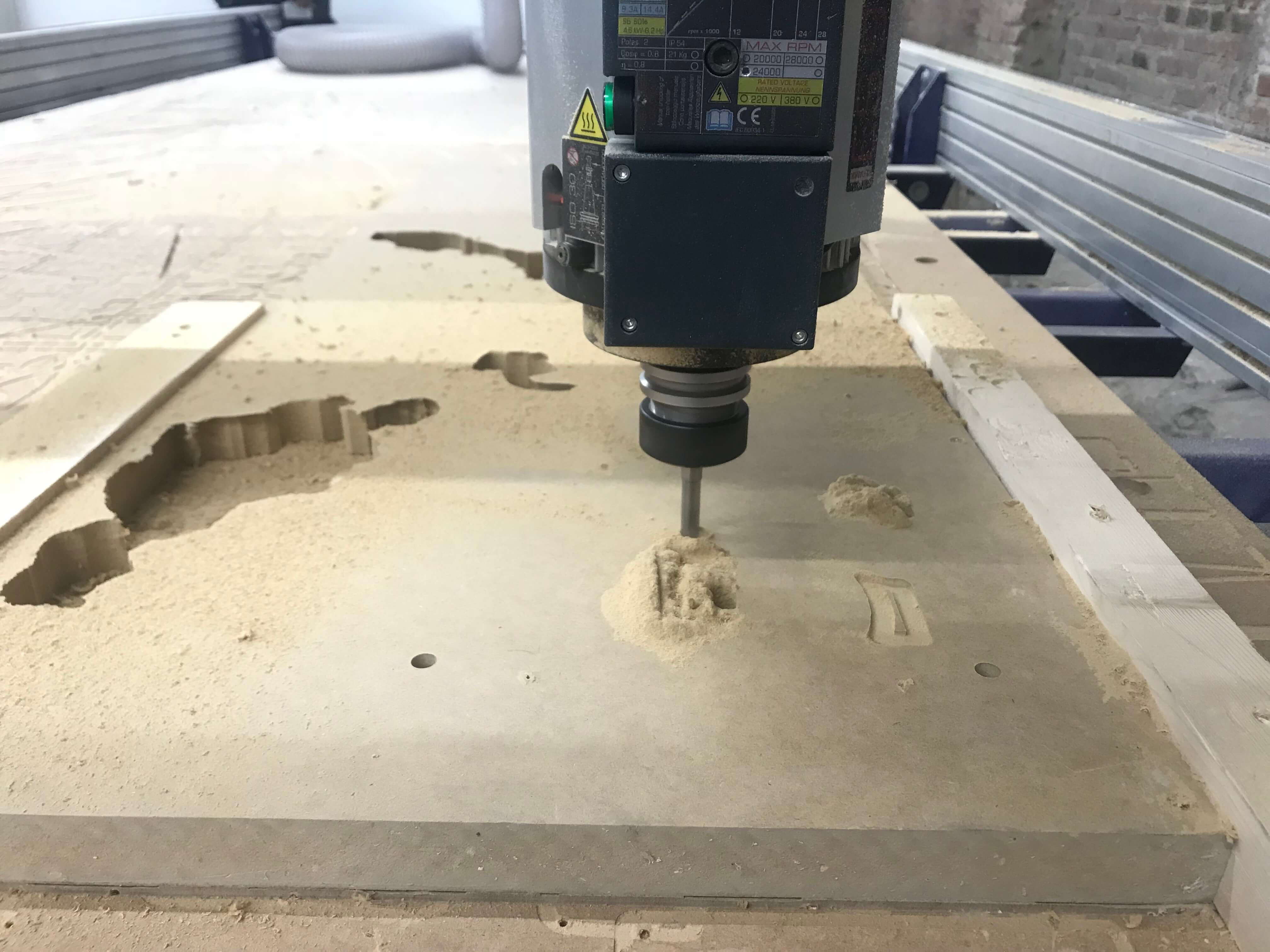
#start milling
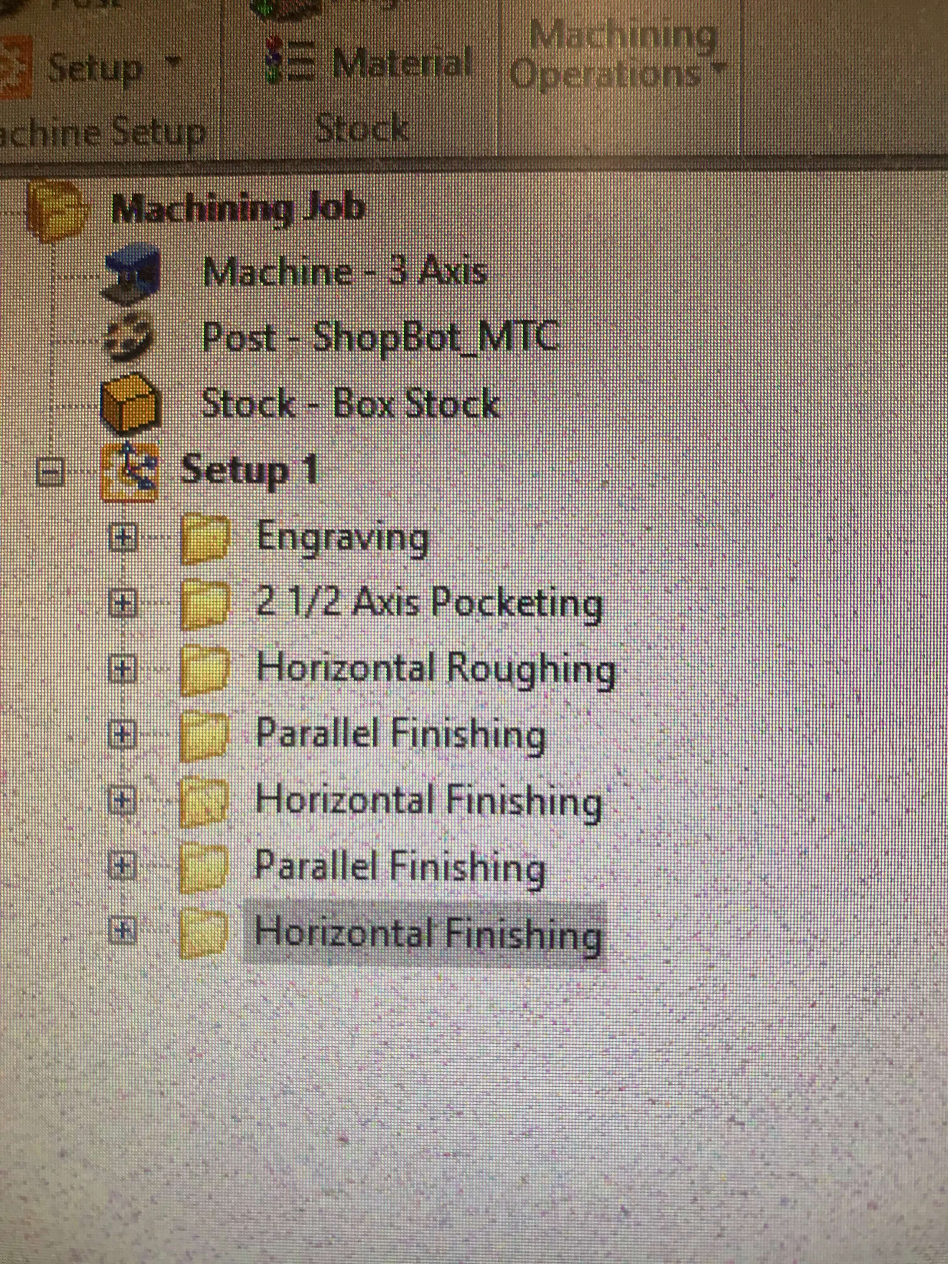
just to recap - those processes were generated
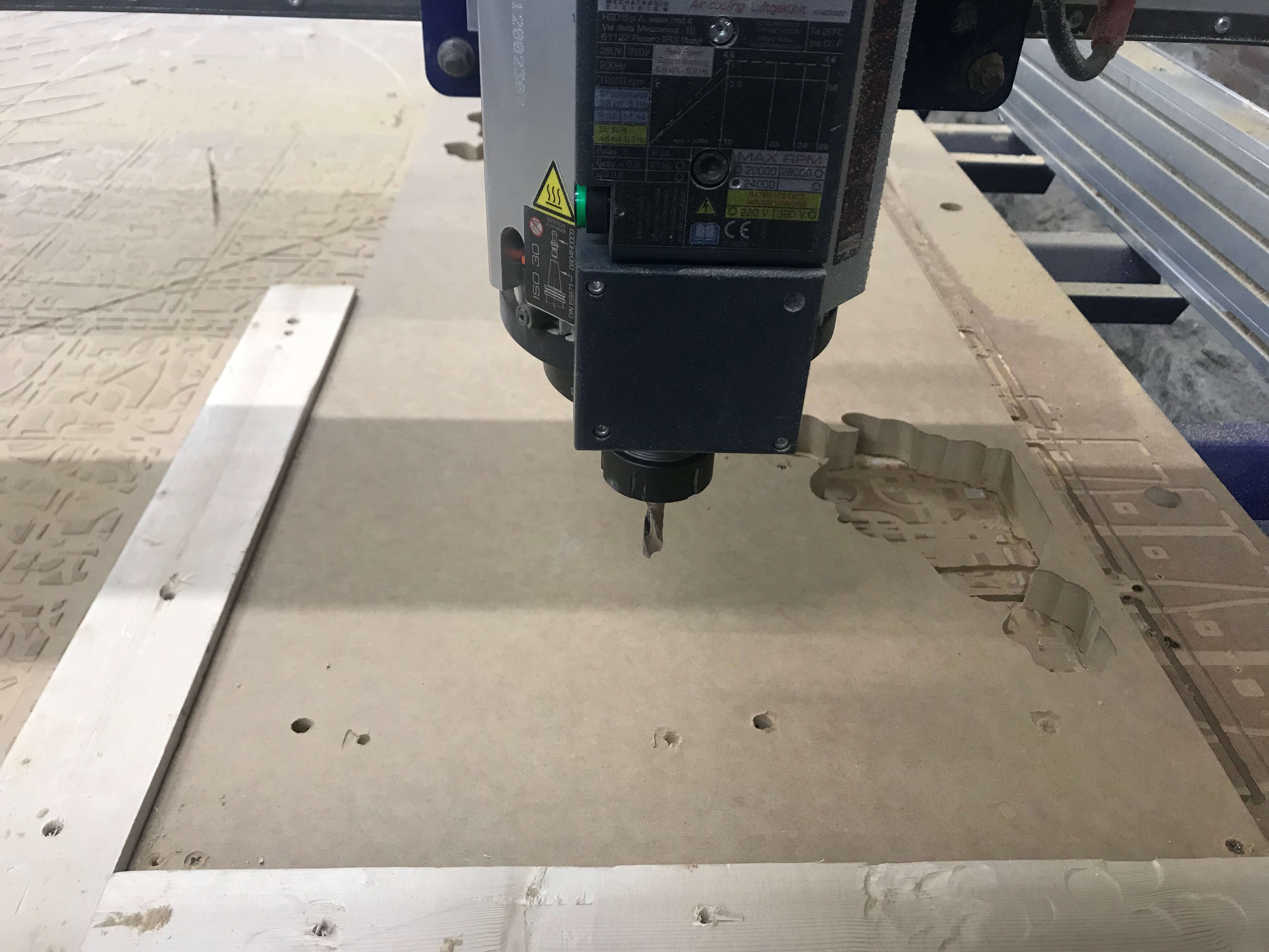
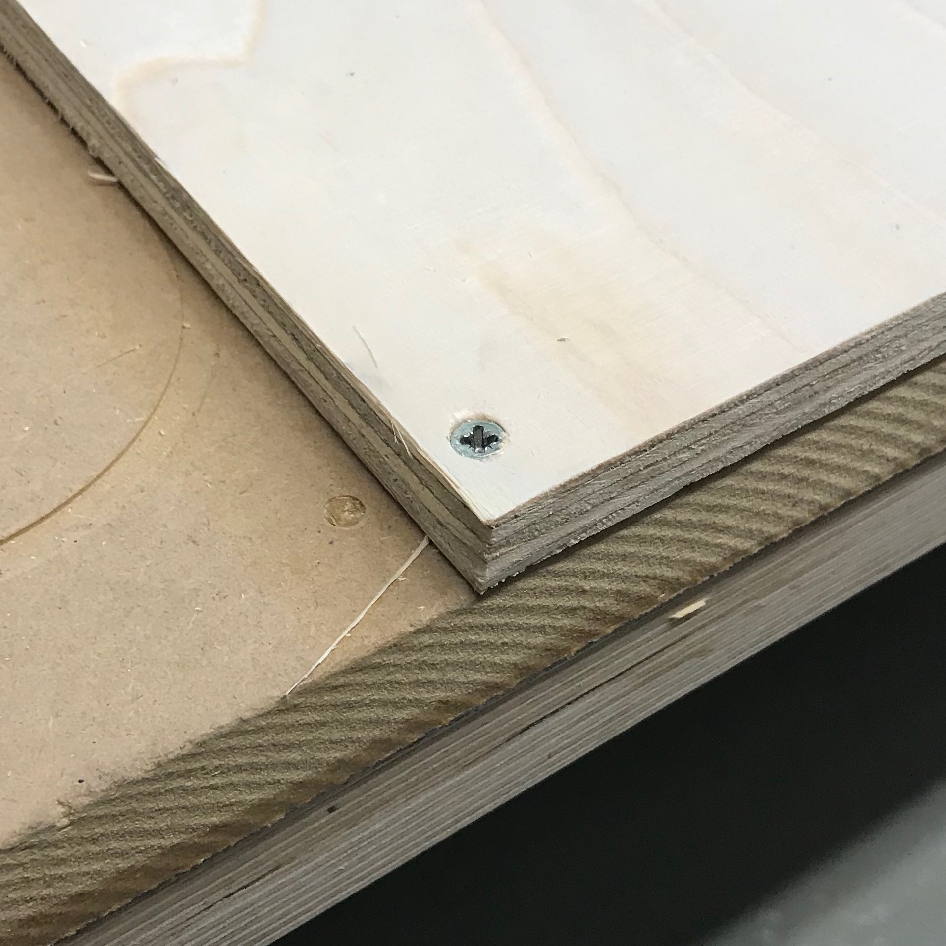
for keeping the same position we milled 2 holes to keep the right alighnment. it was helpful for following the correct path from the other side.
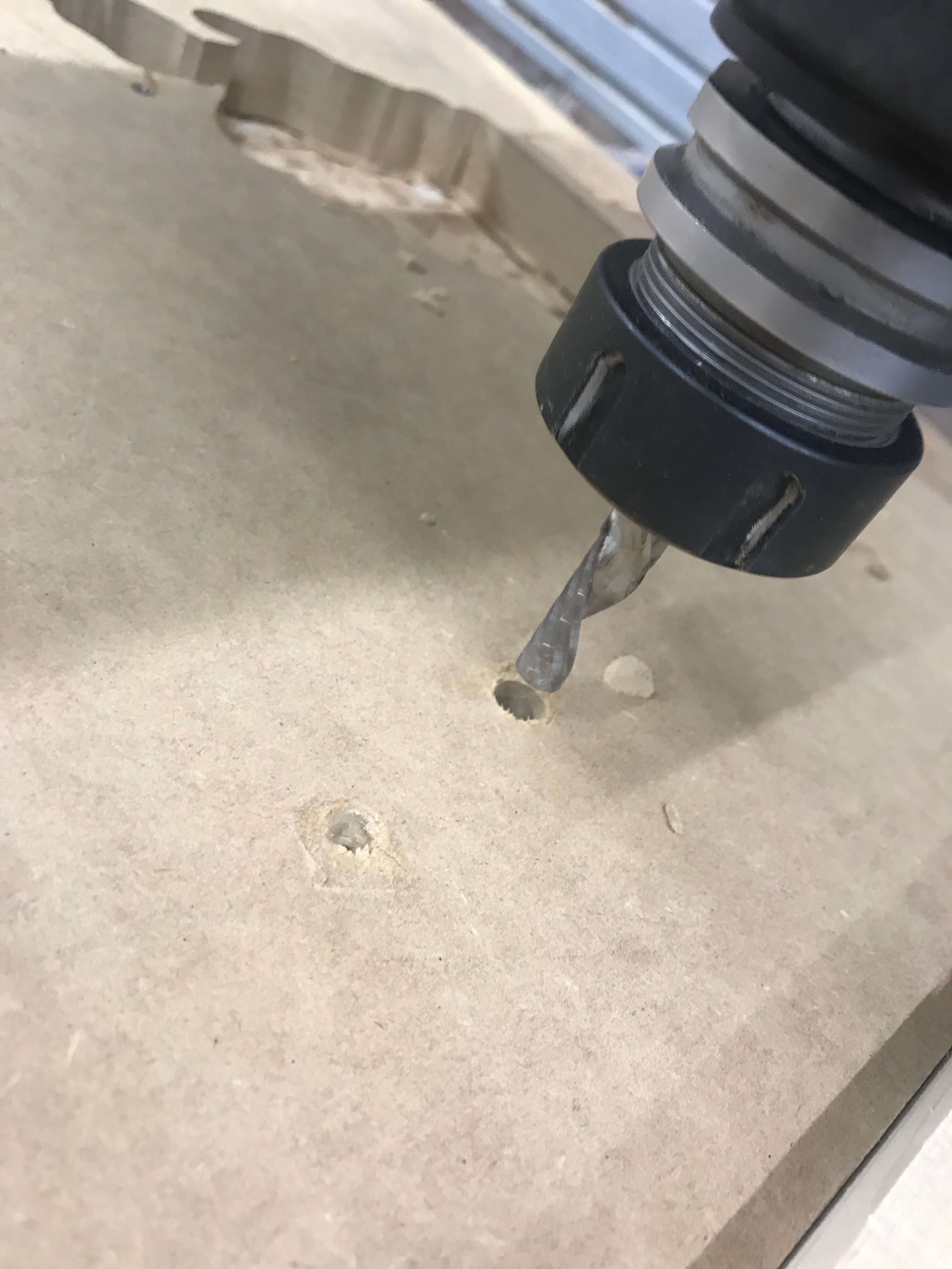
just slowly move the drilling bit and fit it with the hole.