experimentation
Group Assignment:
Group Assignment - participants:Josep Marti, Felipe Santos, Alberto Lopez, Diar Amin, Gustavo Abreu
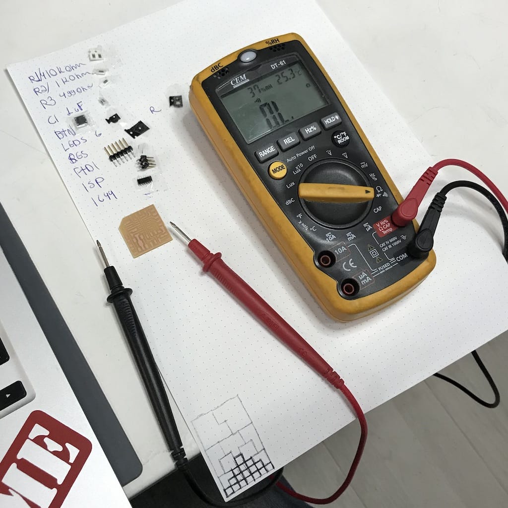
We’re still going to have a oscilloscope class. So for now, we will test our own boards with the multimeter.
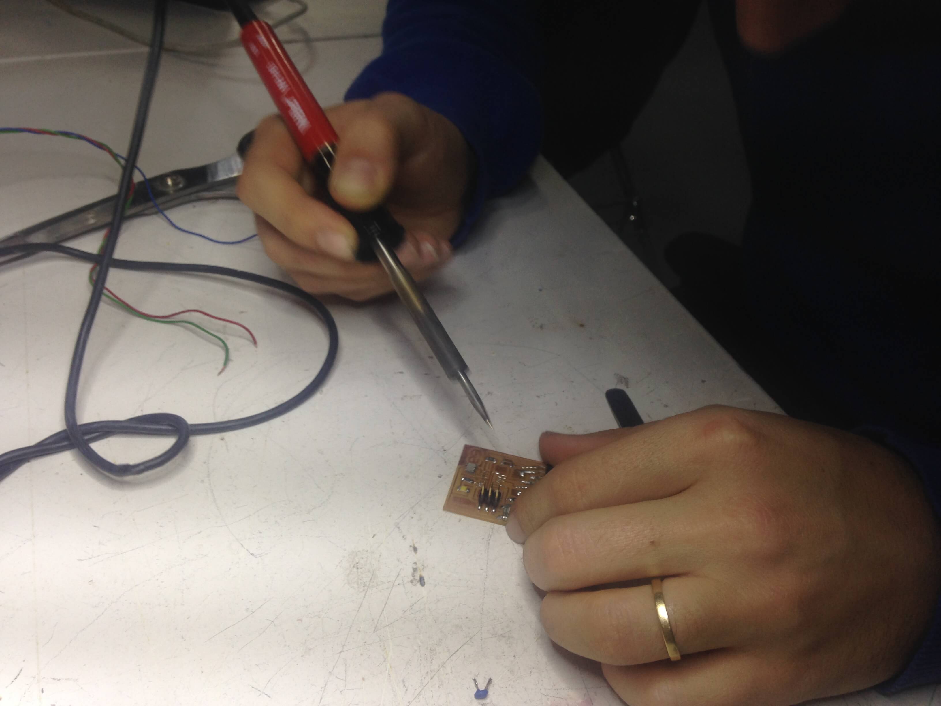
First, we checked the boards continuity before and after soldering. Everything looks good.
Then, voltage powering the LED, before and after the resistor.
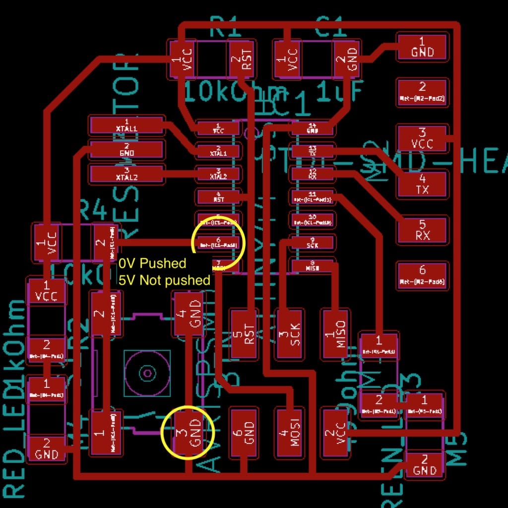
Understanding the button state is really easy when you measure the voltage on the IC port.
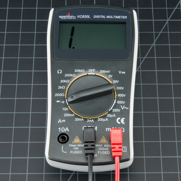
Multimeter is set to continuity mode. Image from Sparkfun.
Now it was a time to get familiar with this device, because we will use it troughout the whole Fab Academy course. The Multimeter helps us identify and recognize the values of voltage, resistance and current. It combines three essential features: a voltmeter, ohmeter, and ammeter, and in some cases continuity. It is a measurement tool absolutely necessary in electronics.
So what exactly is the multimeter? Sparkfun link, Begginers Guide, WikiHow, Here
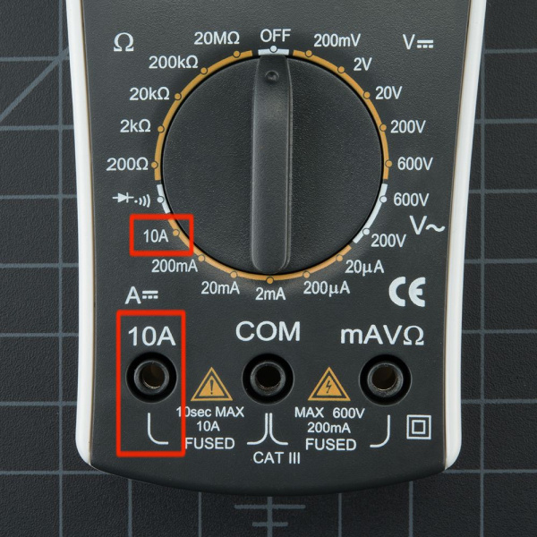
Remember: If your system has the potential to use more than 100mA you should start with the red probe plugged into the 10A port and 10A knob setting.
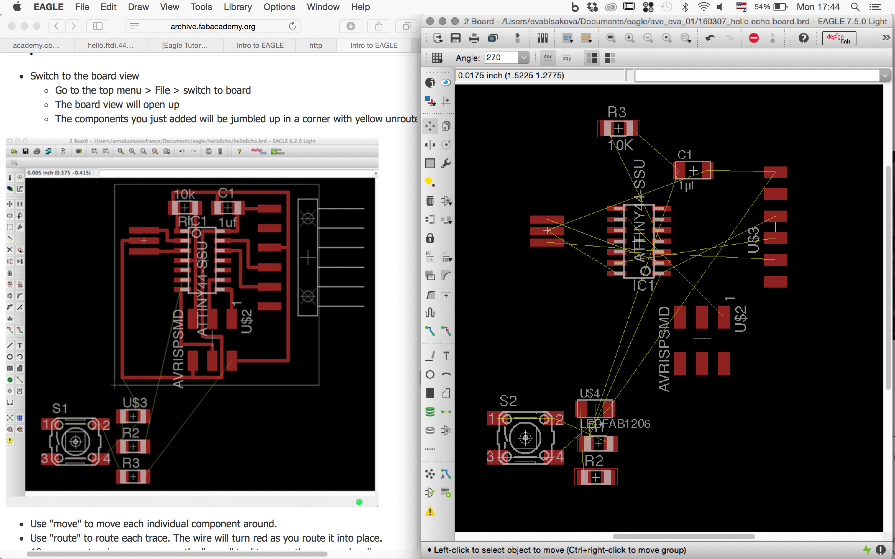
...coming from 2016 to 2019...meanwhile Eagle bought Autodesk...reinstalling SW process...and refreshing the knowledge again...I went trough the new EAGLE tutorials on the Fab Academy website tutorials here
The task was to make a HelloBoard with LED and Button. When we use LEDs in circuits we always use a series resistor. For that it is important to know how to calculate its value. This website is very helpful for understanding the resistors value and its calculation and you can even calculate it online there! It includes LED calculator! just go to thils this link.
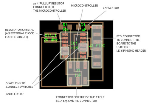
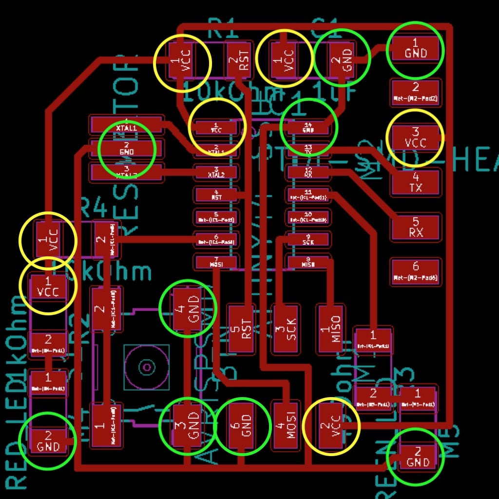
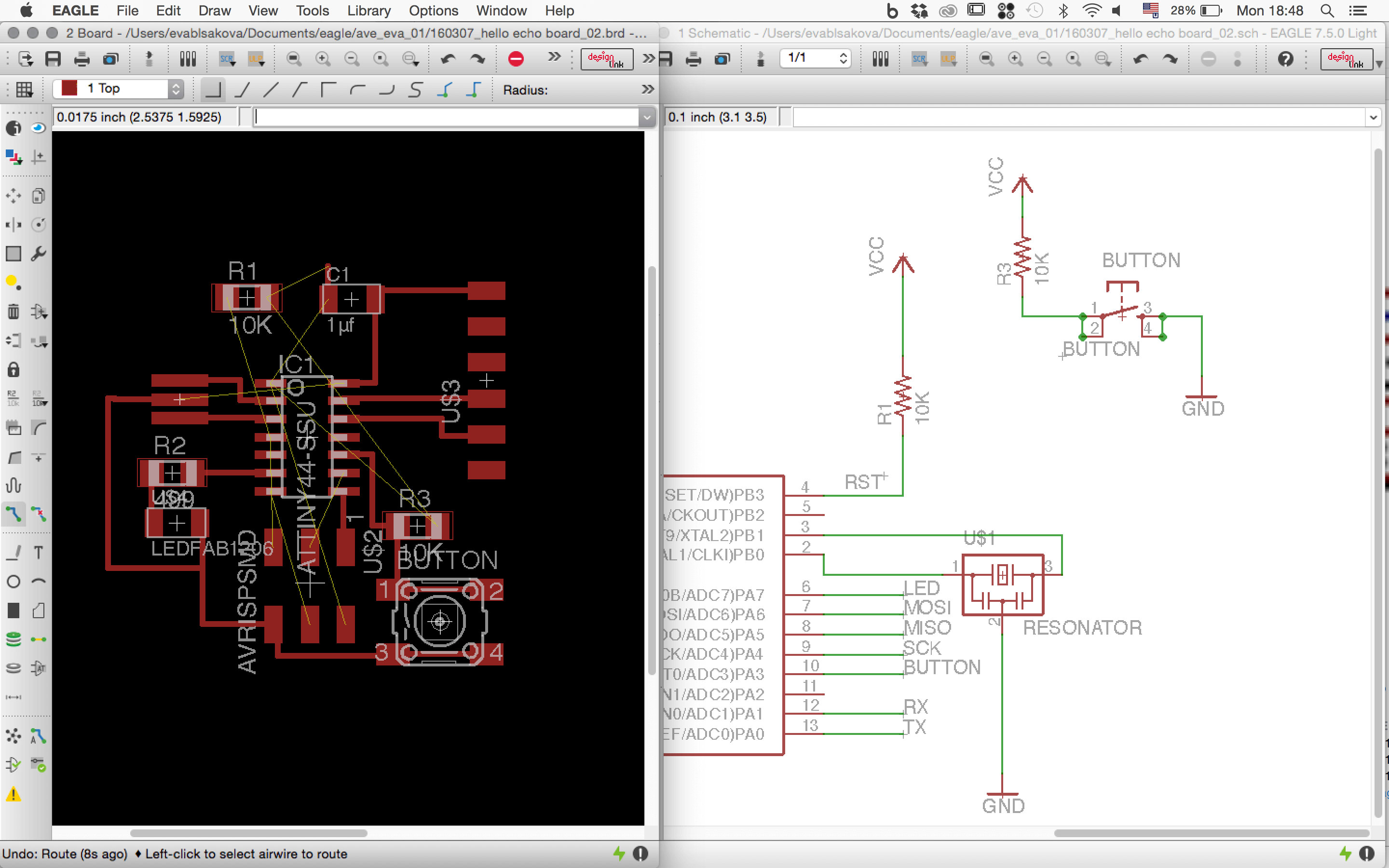
As a good starting point is good to check Neil’s board and to understand what components are included. I found this great documentation from past fab academy student very helpful. So on the diagram is showen also explanation what components it consists and what they are able to do - from the ATTiny44, this is what we have: * Microcontroller: this is an ATtiny44 programable chip that controls all the parts on the board and is programmed from the computer. * Pull-up resistor: this 10K resistor keeps the power flowing into the microcontroller steady near VCC or zero and needs to be connected to the VCC pin on the ATtiny. * Capacitor: this is a device used to store electric charge, consisting of one or more pairs of conductors separated by an insulator. This will help filter devices to remove voltage or signal spikes in our circuit. * FTDI Connector: This will connect the circuit to the computer to both program and power the board. It’s VCC and GND pins need to be connected to the respective VCC and GND circuits on the board, and it’s Tx and Rx pins connect to the two free pins on the microcontroller. * SMD Bus Connector: Takes in information from the FabISP and connects it to certain pins on the Microcontroller to program the board. This also needs to be connected to VCC and GND on the respective pins on the Microcontroller, and the other pins need to be connected to free input and output pins. * Resonance crystal: This is an external clock for the circuit. It needs the input traces to be connected to two pins on the board and the ground trace to the GND circuit. * Spare pins: these are the free pins on the chip to which we must connect our button/switch and LEDs.
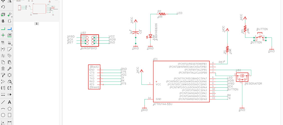
So I started with the design of Hello Board in Eagle. This is the tutorial to follow to get on the Eagle track. As I did too :) So open Eagle/Create a new project, and new schematic (save it both otherwise you are risking loosing your data). This layout allows me to start adding in my components. To do this I used the add button on the left toolbar, which pops up the library window with millions of components. They are listed alphabetically, so under the fab library I was able to locate and choose all the components for my board and connect them where is needed >use NET tool for that.
I followed the tutorial what we had online in fab academy handbook. It was very easy to continue its instructions.
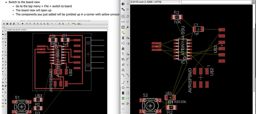
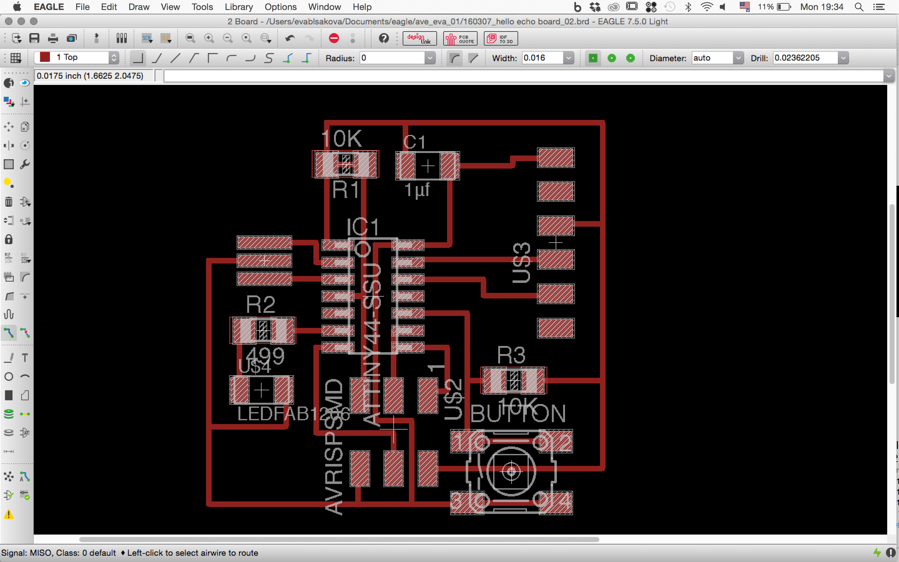
Start to connect wires. Yellow connection needs to be transformed to real path. So make traces. Good strategy is to do it while placing components, that way you avoid being lost or using jumpers later when there would be no possibility to connect wished path.
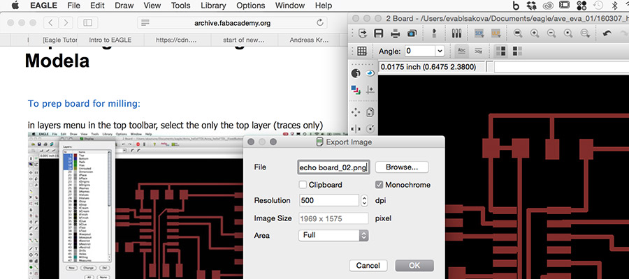
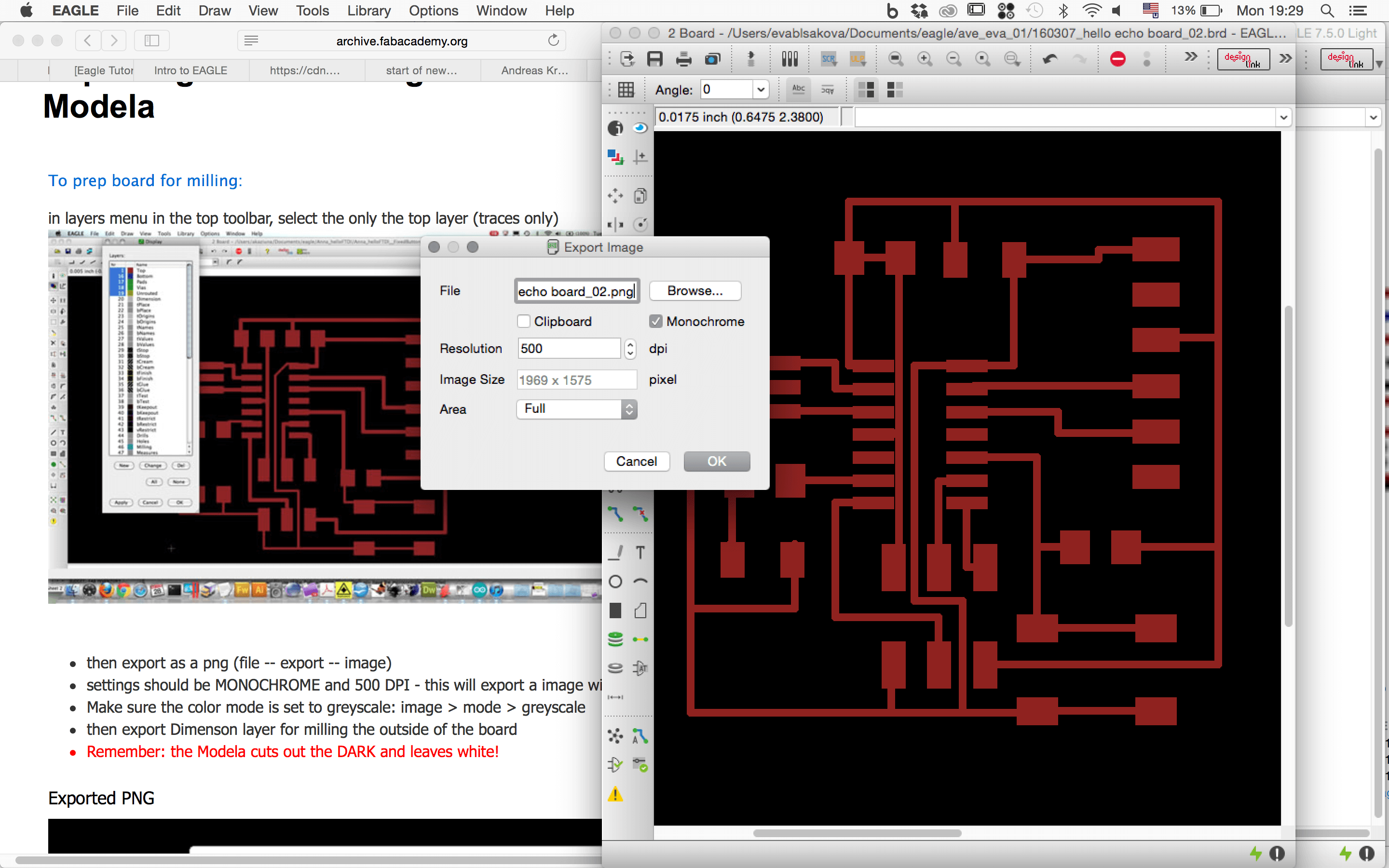
Once you connect all wires...export the image as .png (monochrome, resolution 500 - this was back in 2016, now we do export 1000, and in MAC because of some bug we change the image size in photoshop -50%)
I took it to photoshop to label it.

Now I had to update my fab libraries and also Design Rules for milling. I had to download those files and upload them to the Eagle. On Mac they are in /Applications/EAGLE/lbr/ top toolbar and select the "Library" menu Select "use".Select all the libraries with 01 in front and click "open".
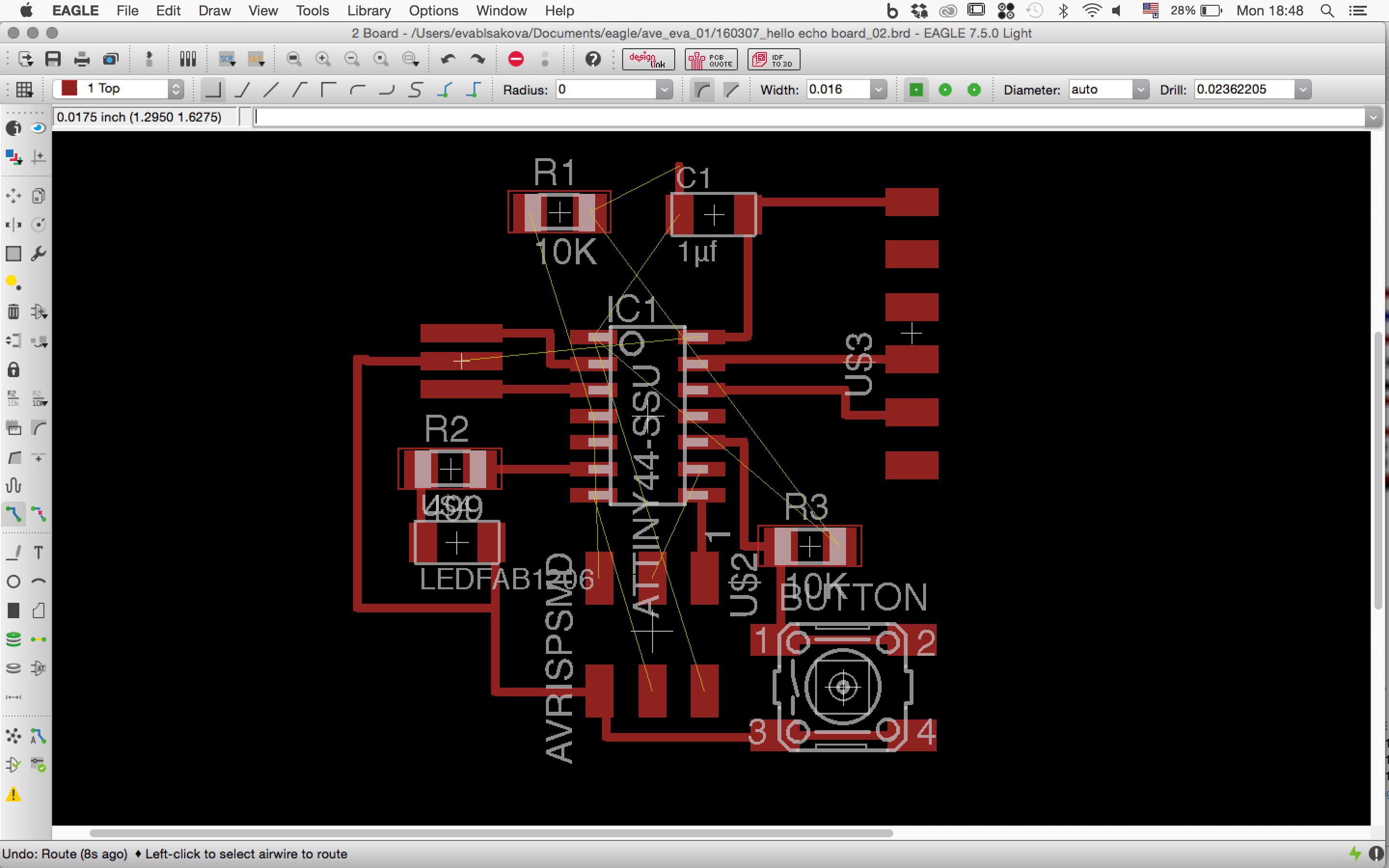
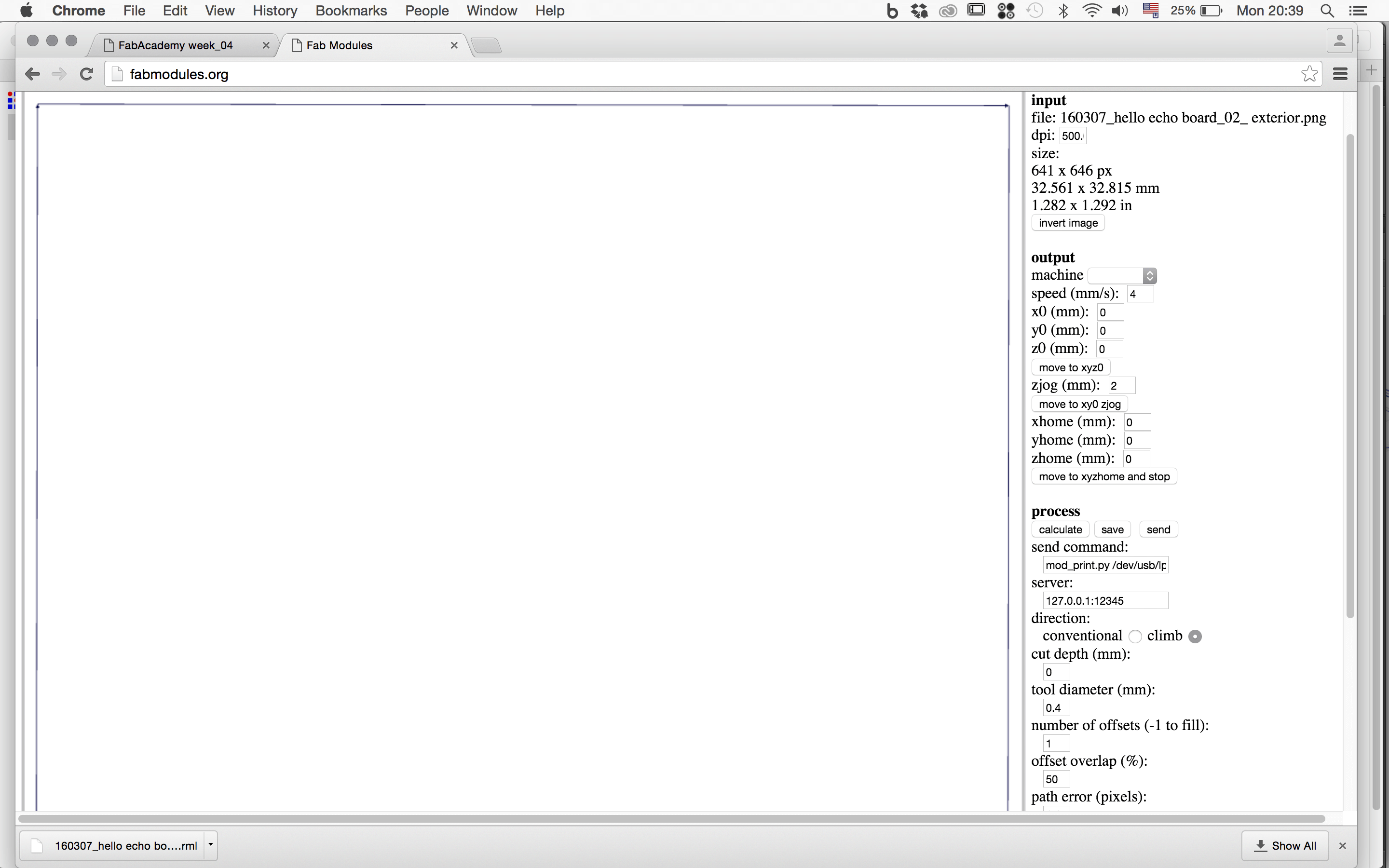
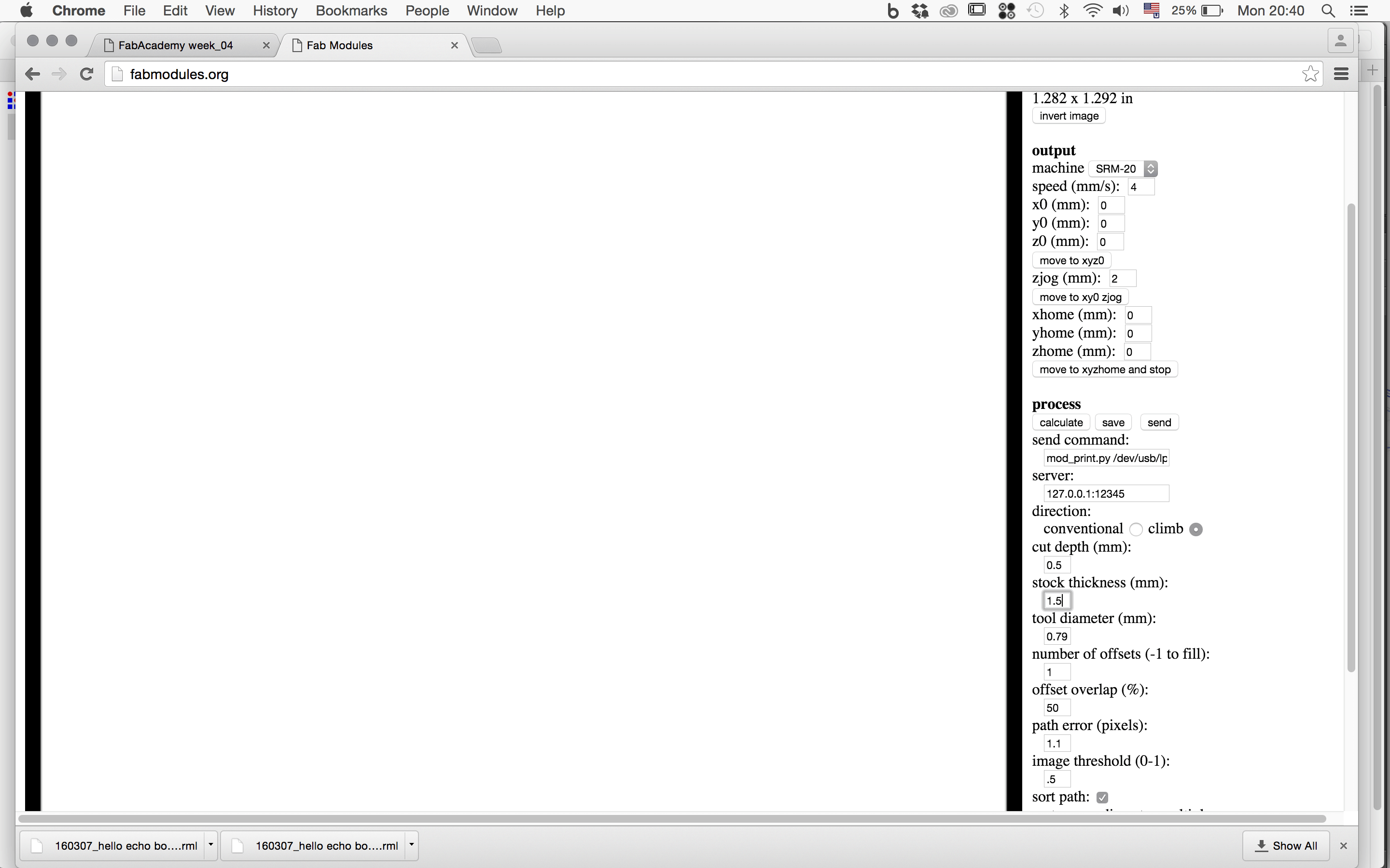
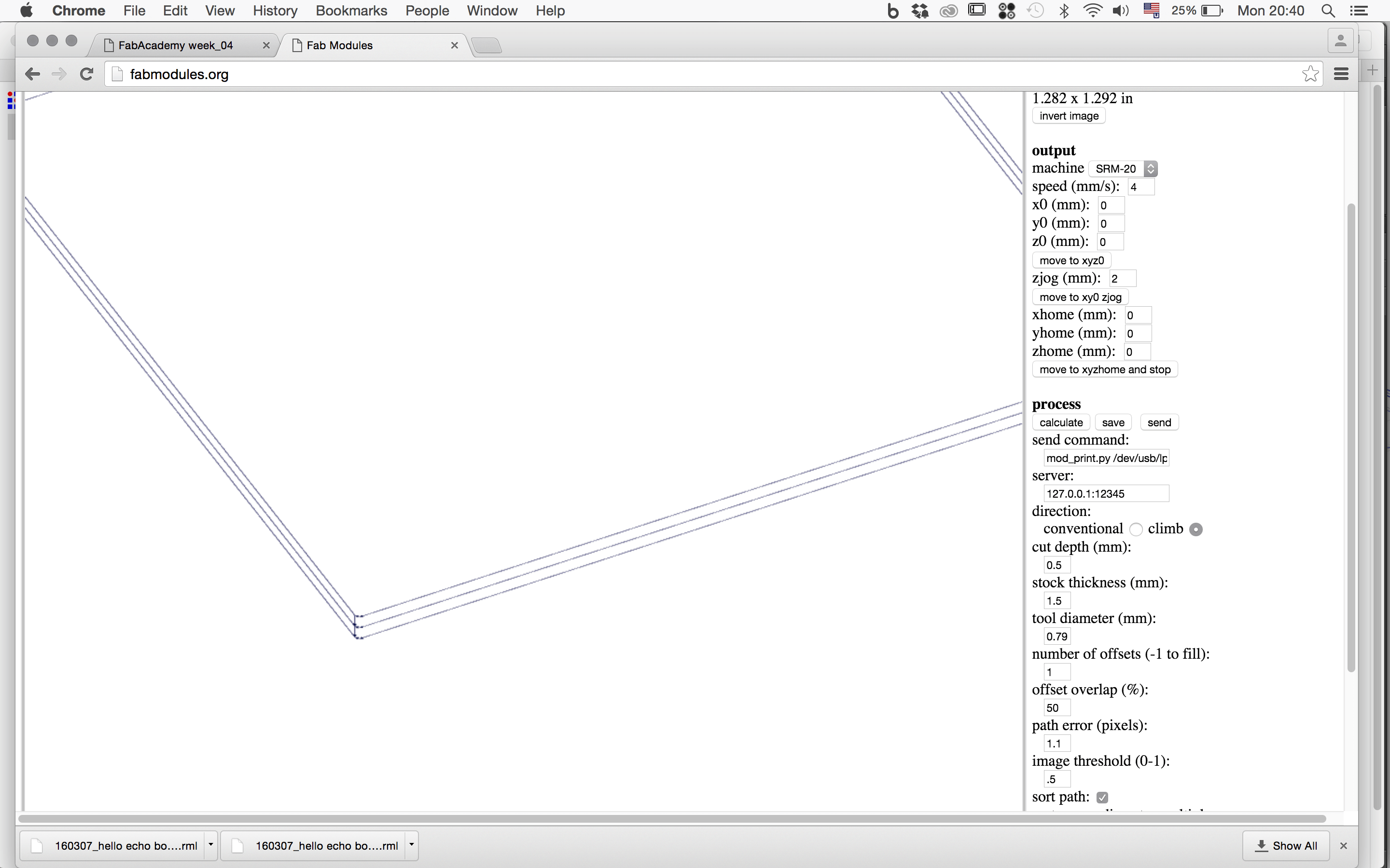
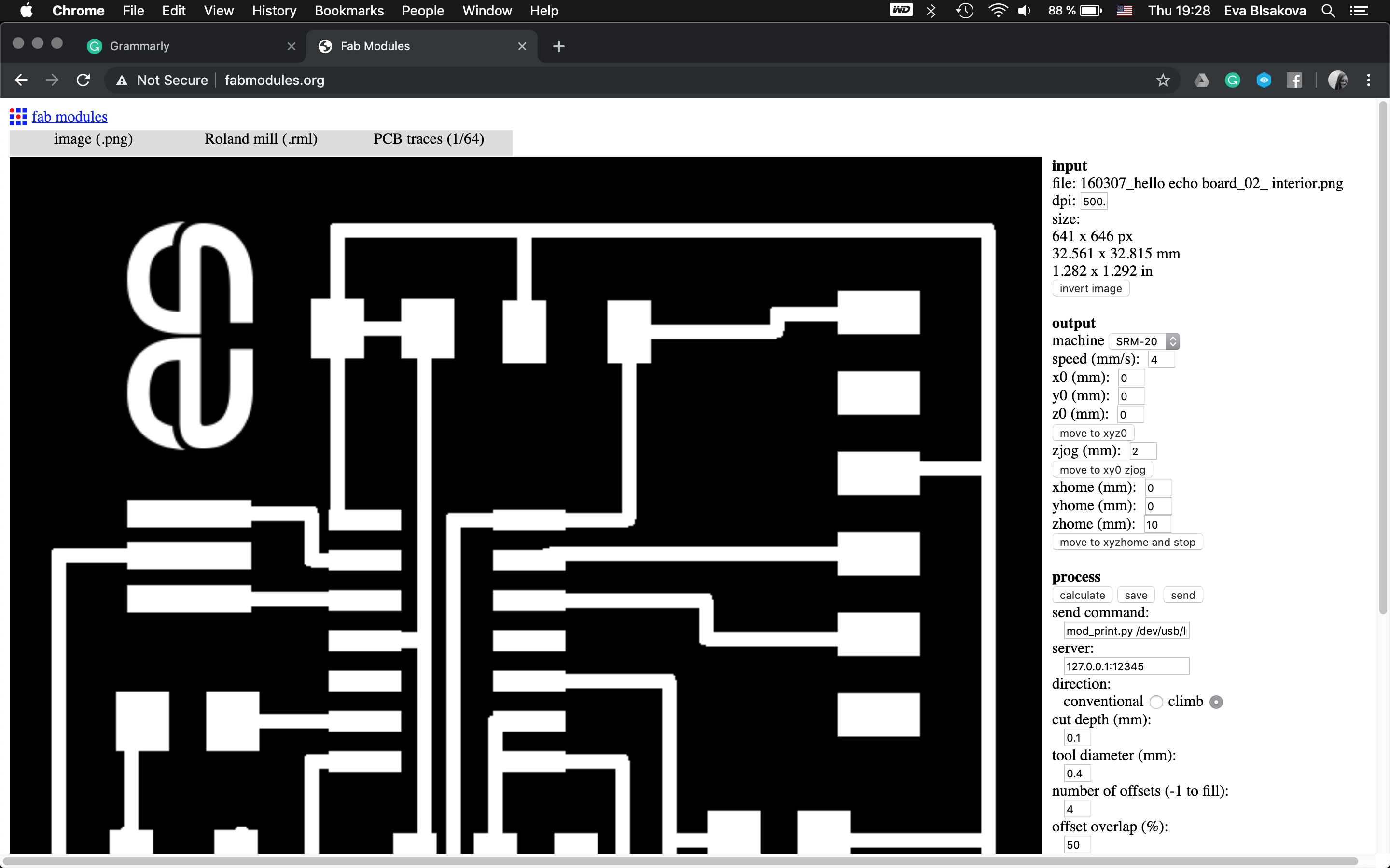
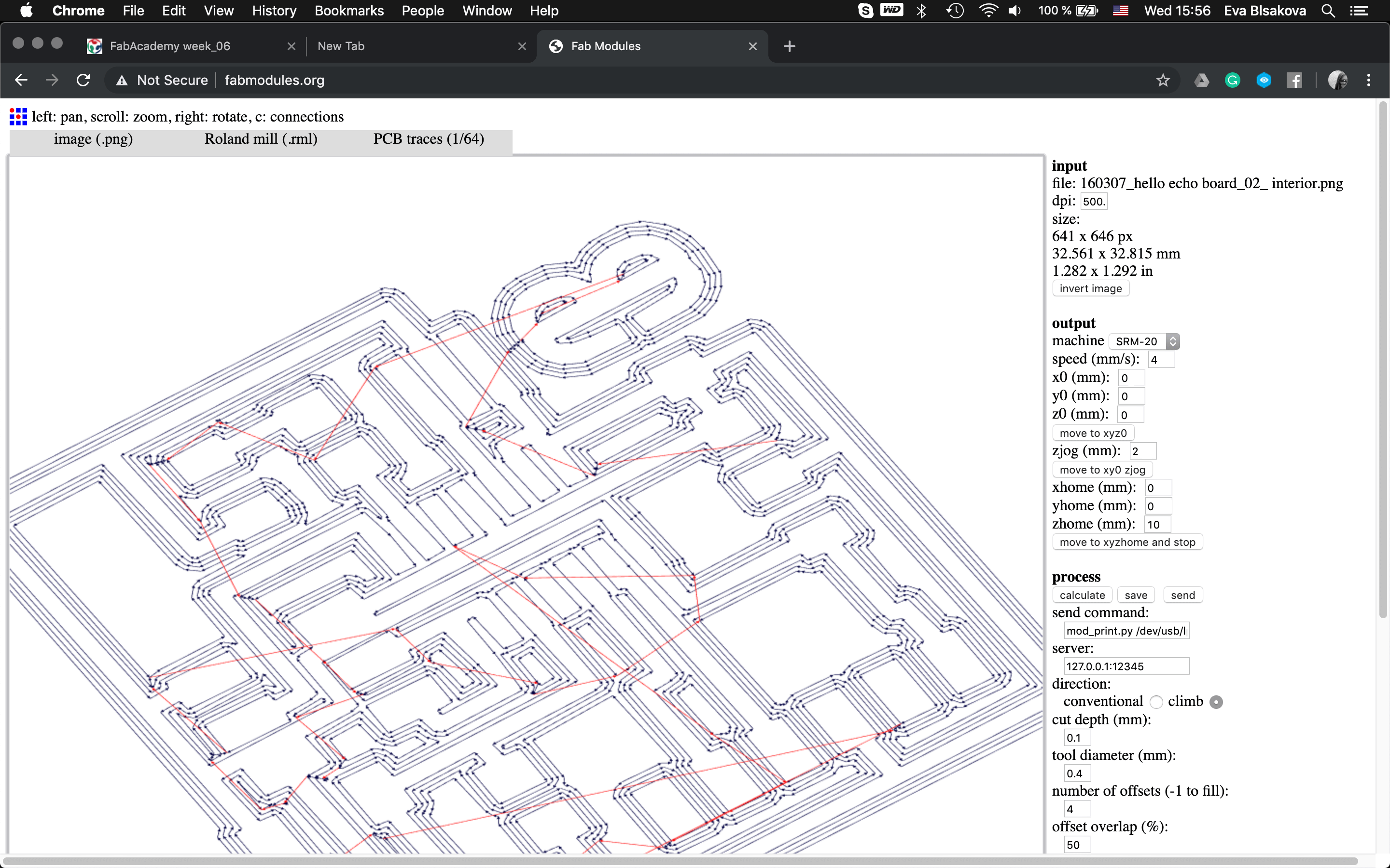

To check the board if it's millable / its traces, if they are too close and the machine will cut them perfectly or if they're too close, perhaps overlapping, we use the test called Design Rule Checking (DRC). Go to fab modules and export milling files for traces and outline. DRC = design rules check (in board view) - keep all the default settings (16 mil is fine); it should display a "no error" message in the bottom left hand corner of the screen...So download the DRC script from here
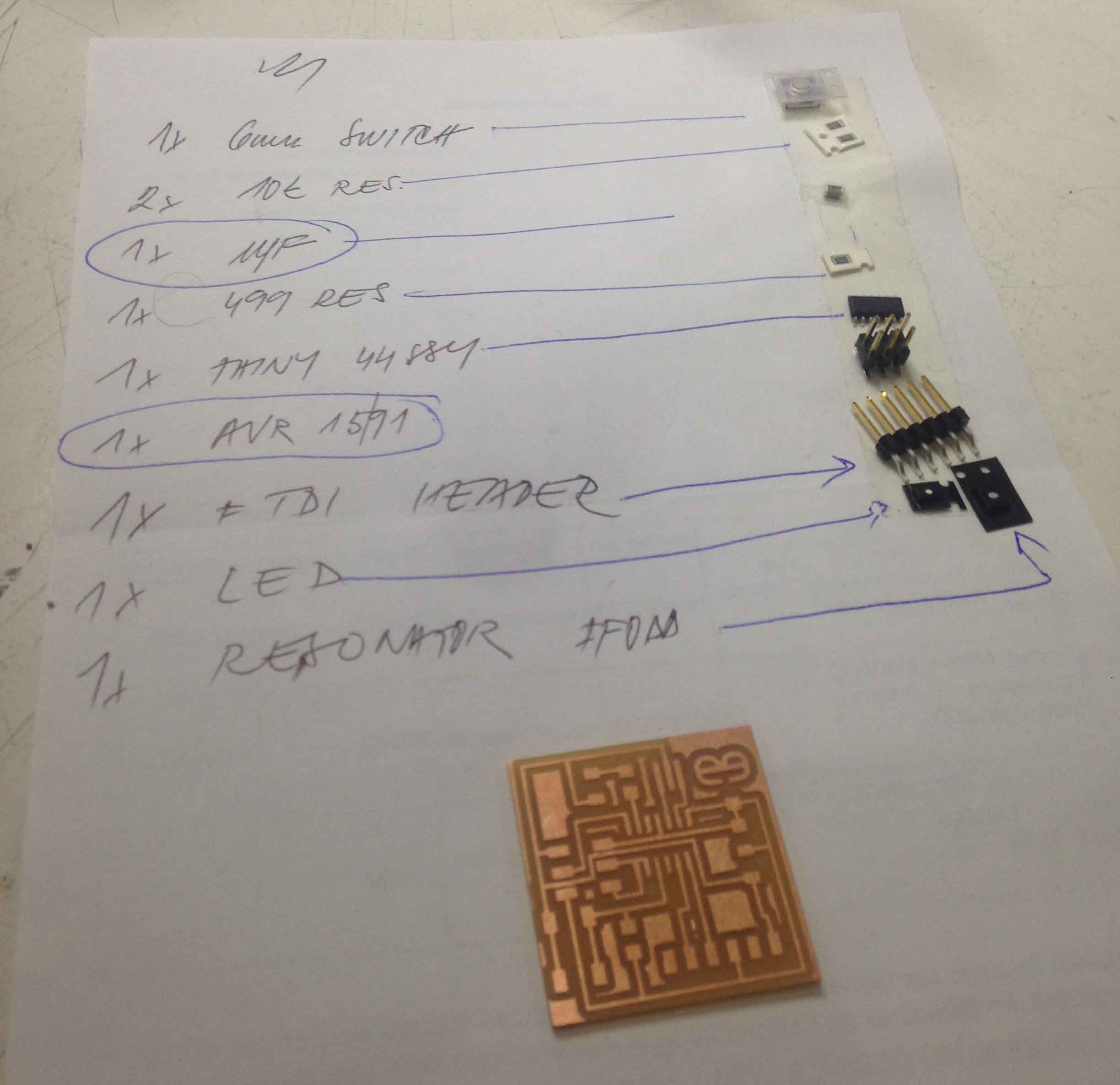
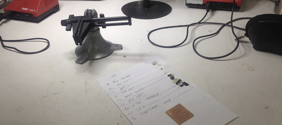
Prepare needed components...its good to put them together on a paper sheet on one side name of the component and on the other side placed component on the double sided tape - that way is harder to loose it while soldering process.
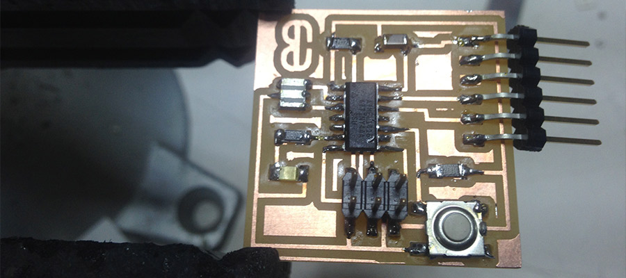
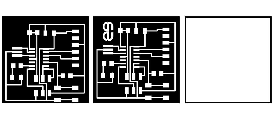
Solder them onto the board and it should looks like that.
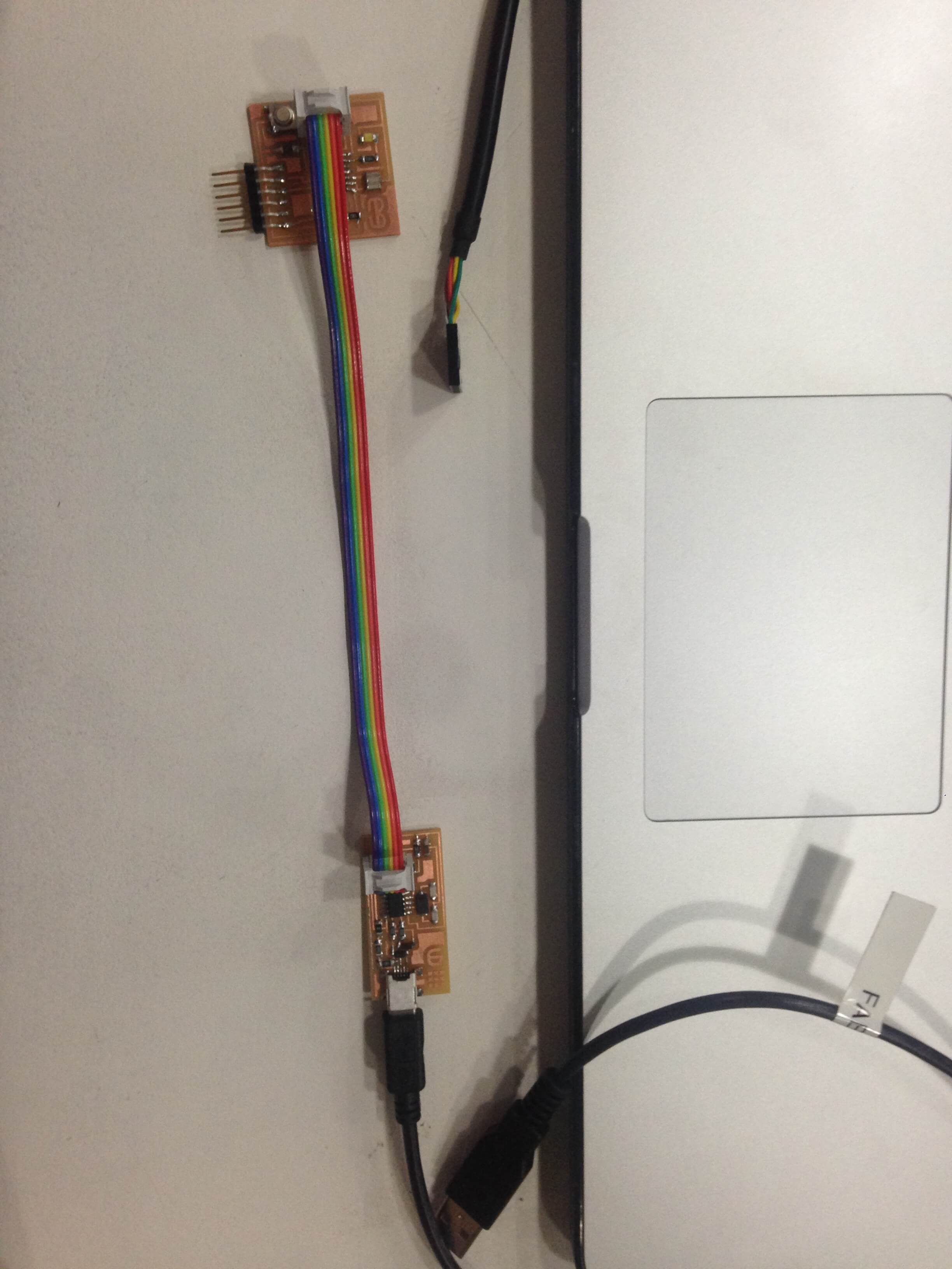
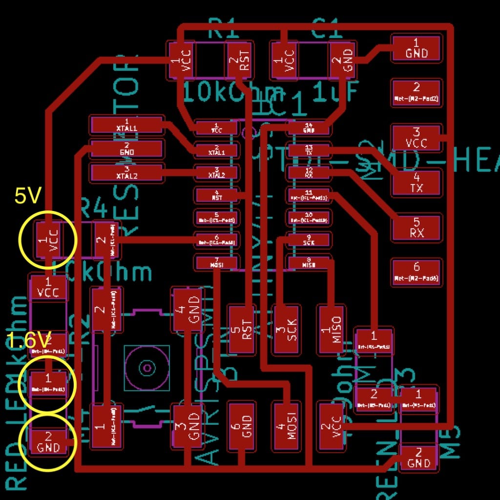
First testing with multimeter looked ok. So I connected it also with fab ISP and tried to programm it, but unfortunately I was not able to recognize the connections. As you can see on the picture, I tried to connect and disconnect wires, still not communicating...