experimentation
make it happen
Group Assignment - participants:Josep Marti, Felipe Santos, Alberto Lopez, Diar Amin, Gustavo Abreu
Test file
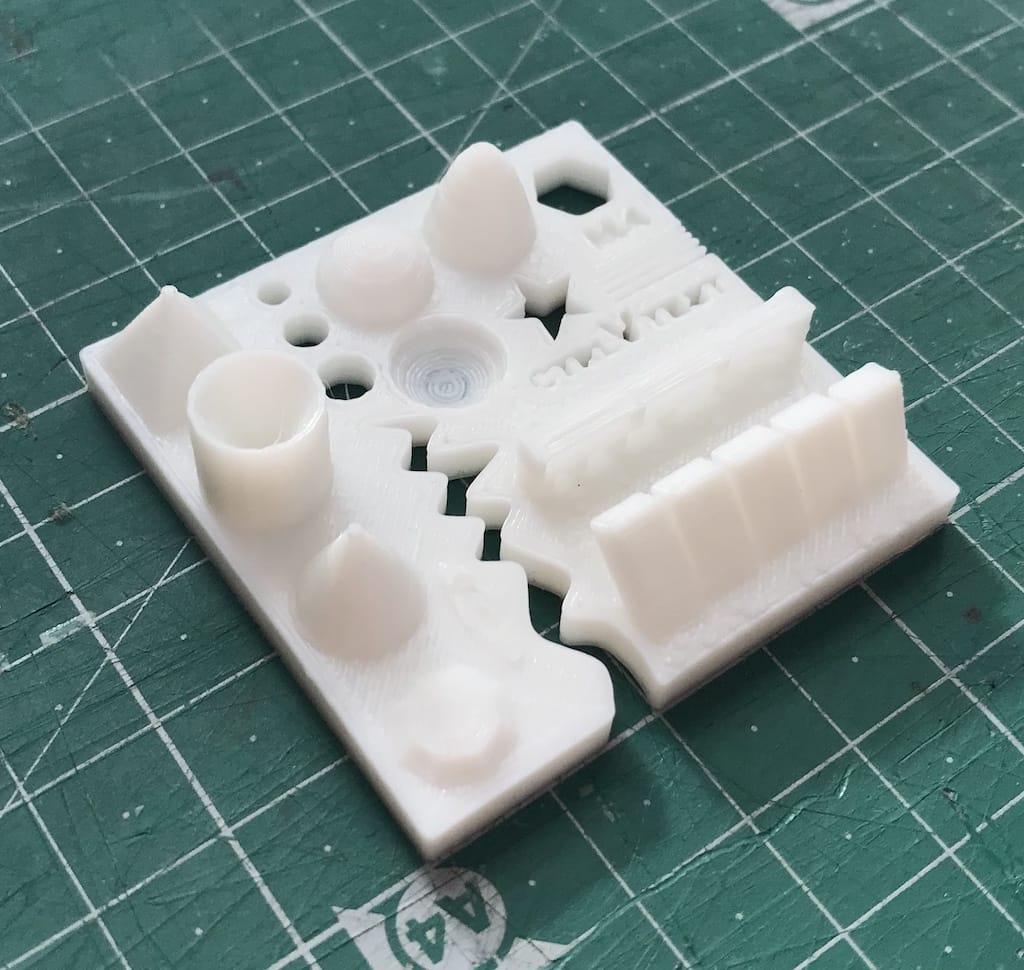
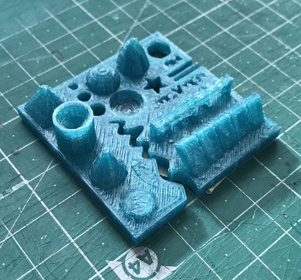
To test the different printers, the best option is to print a part that shows how the printer behaves in different situations.
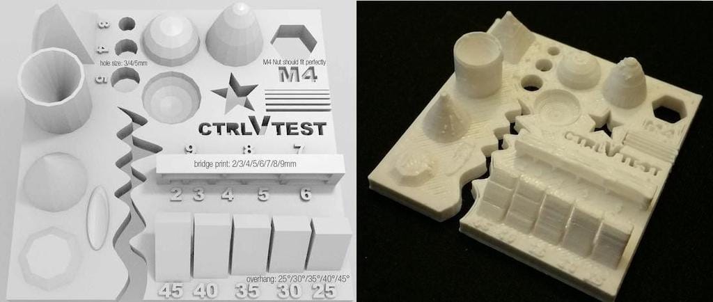
To do this, we’ve used a file from 3dprint.com available on thingiverse.
The article explains what should be measured as pointed below: Size: the object is 4 x 50 x 50 mm (baseplate) — measure with a caliper Hole size: 3 holes (3/4/5mm) — measure with a caliper/drill Nut size: M4 nut should fit perfectly — insert an M4 nut; it should need a little pressure Fine details: pyramid, cone, all numbers — check if all things look nice and smooth Rounded print: wave, half sphere — check if all things look nice and smooth Minimum distance between walls: 0.1/0.2/0.3/0.4/0.5 mm — depending on your nozzle size and slicer settings you will get different results Overhang: 25°/30°/35°/40°/45° — depending on printed material/cooling, these will not be as seen on the rendering provided Flatness: all flat areas — these should be flat with no gaps
We’ve used the same slicing parameters on every machine to have somewhat similar results. Although we could not use the same filament since the diameters were different. Slicing settings: Layer height: 0.2mm Wall line count: 2 Top layers: 6 Bottom layers: 4 Infill: 20% Speed: 60mm/s Nozzle temp.: 205 Bed temp.: 60 Material: PLA
Printers description
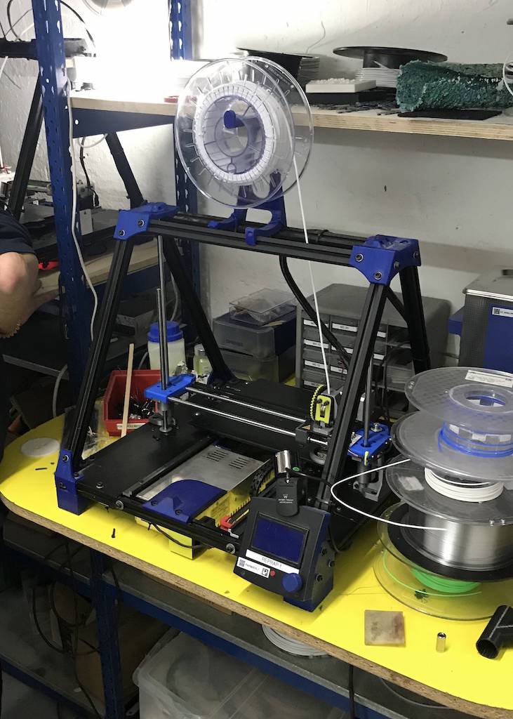
Anycubic Kossel Plus
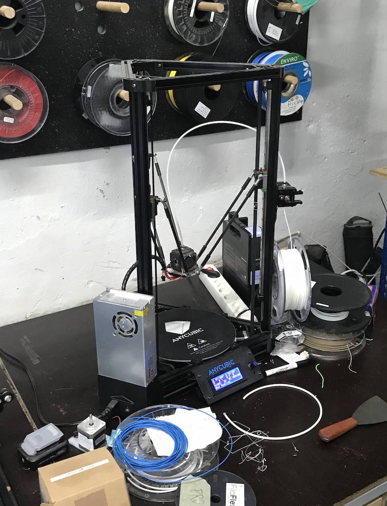
Area (x,y,z): 23x23x30 How to print: SD card Nozzle diameter: 0.5mm Filament diameter: 1.75mm Axis movement: Delta
Ultimaker 2
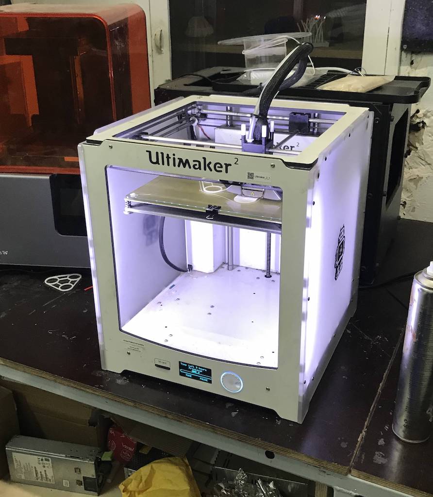
Area (x,y,z): 22x23x20 How to print: SD card Nozzle diameter: 0.4mm Filament diameter: 3mm Axis movement: CoreXY
RepRap
Area (x,y,z): 24x23x20 How to print: SD card or Octoprint Nozzle diameter: 0.6mm Filament diameter: 3mm Axis movement: Cartesian
Prusa i3 Mk3
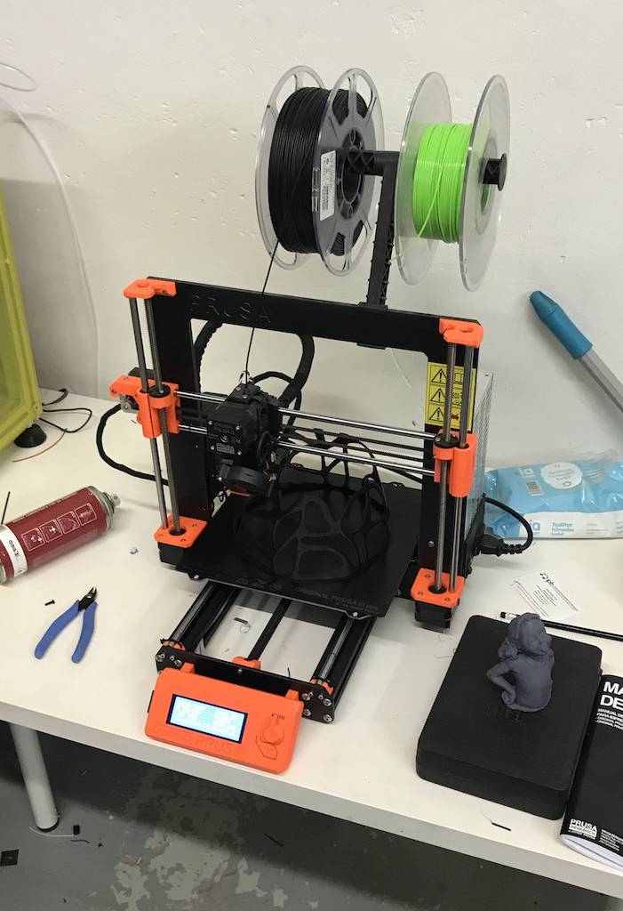
Area (x,y,z): 25x21x20 How to print: SD card Nozzle diameter: 0.4mm Filament diameter: 1.75mm Axis movement: Cartesian
Print tests
Prusa i3
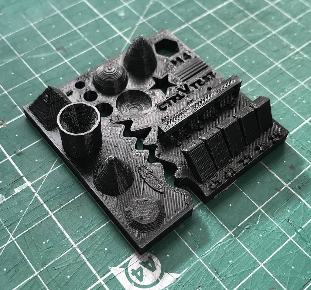
Size: 4x50x50mm Hole size: 4.7,3.7,2.5 Nut size: Snug fit Fine details: Smooth Rounded print: Smooth Minimum distance between walls: 0.3mm Overhang: Up to 45º smooth Flatness: All closed Bridges: Up to 9mm smooth
Ultimaker 2
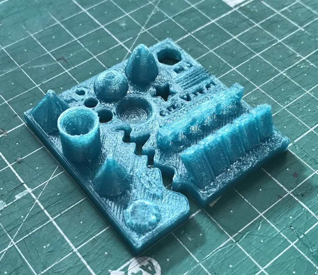
Size: 4x50x50 Hole size: 4.6,3.7,2.3 Nut size: Snug fit Fine details: Smooth Rounded print: Smooth Minimum distance between walls: 0.3mm Overhang: Up to 45º smooth Flatness: All closed Bridges: Up to 9mm smooth
Anycubic
Size: 4.1 x 50 x 50 mm Hole size: All of the drills almost fitted Nut size: Almost fitted but not entirely Fine details: Looks nice and smooth Rounded print: Looks nice and smooth Minimum distance between walls: Problems only with the 0.1/0.2mm wall distances but printed nicely Overhang: No problem printing the overhangs Flatness: Flat with no gaps Bridges: It printed it all but with a little problem in the bridge of 6mm
Reprap
Size: 4.1 x 49 x 49 mm Hole size: Any of the drills fitted at all Nut size: Doesn’t fit Fine details: Looks nice but not smooth Rounded print: Looks nice but not smooth Minimum distance between walls: It could print only one wall with wrong distances Overhang: No problem printing the overhangs Flatness: Flat with no gaps Bridges: No bridges at all
Conclusions
The Prusa i3 Mk3 did the best printings with accurate measurements, nice bridges, overhangs, spaces between walls and a lot of details. Anycubic and Ultimaker had similar good results. The worst result was on the Reprap, we believe we could fine tune the slicing to improve the print. But, other than it having a 0.6mm nozzle, the main reason could be the old filament we’ve used. We may try again with a new one as soon as it arrives. Since we had to use different softwares and filament between printers, we had very different results, but overall, they were good prints.
Individual assignment:
Identify the advantages and limitations of 3D printing and scanning technology
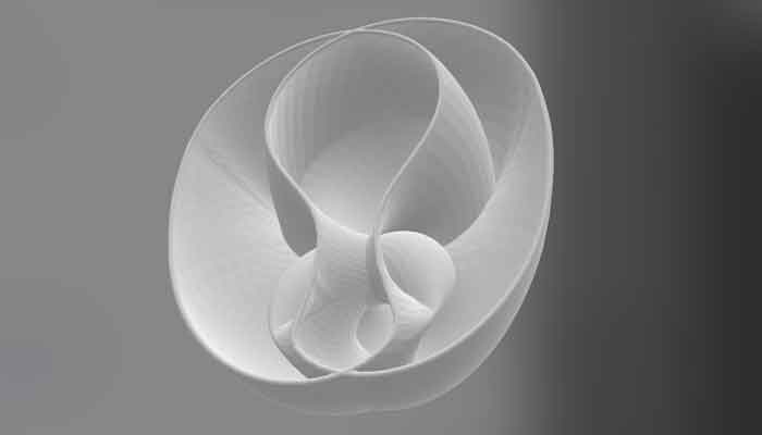
The form of my design has a number of limitations related to the complexity of the final product geometry and additive manufacturing as a 3D printing allowes the creation of complex internal features as we can see in my case. 3D printing gives the possibility of manufacturing with hollow or lattice structures what in my case could be very nice for testing also the transparency and visibility, how it behaves when the light goes trough the shell.
Here are explained all 10 types of 3D printing technology in 2019.
The advantages of extrusion-based 3D printing, according to the researchers, are the low costs of the entry-level printers, the variety of raw materials available and the ease of customization. The disadvantages include the low level of precision and the long build time. Of course it depends on the type of 3D printer that we use. There are several sources on the internet that provide different points of view on the advantages and disadvantages of this technology as for example this article Digital fabrication is becoming a part of all branches of design, from architecture to furniture or fashion. Some require large machines, and some can be done with small-scale machines. It always starts with the scale consideration of output object and different objects require different fabrication strategies. I think the main confusion is related to the scale. I would say 3D printing is an over-hyped technology. It has been around since the 80s, now smaller desktop machines became available and affordable, which will allow all of us to manufacture our own objects. The truth is that the desktop 3D printers are not like industrial ones! People think that they can print everything and that they do not need any other manufacturing techniques. It is not true. In the context of manufacturing, only parts of a suitable level of complexity are economically viable for 3D printing. Just because you can 3D print, doesn’t mean that you should! Always consider the complexity of the printed object and decide if using different manufacturing method e.g. laser cutting or CNC machining would be more efficient and provide a better quality of final output. Probably the biggest of all 3D printing myth is that every 3D printer will manufacture the same 3D model the same way. Not true at all. The most important factors affecting the quality of 3D prints are extruders, the diameter of their nozzles, printing temperature and speed, build platforms and if they are heated and casing of the machine. Sure, everybody can buy a 3D printer nowadays but not everyone should. Mostly because not everyone would make use of it. Manipulating a 3D printer requires a certain professional knowledge and objects manufactured this way most aren’t recognized as end products. //read the full interview here
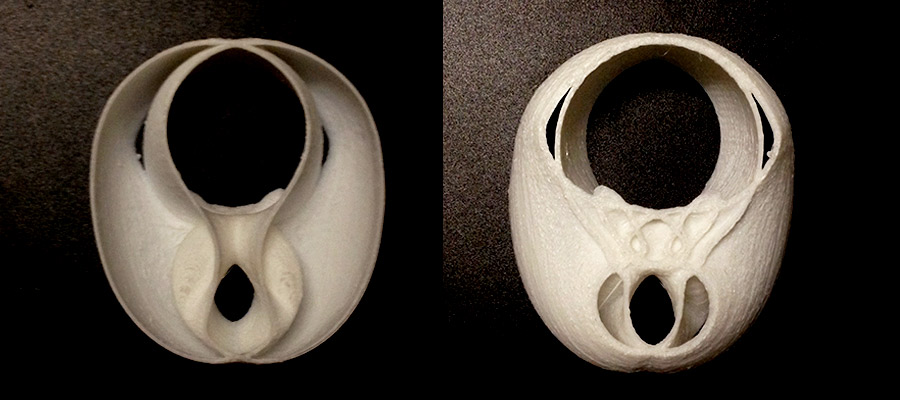
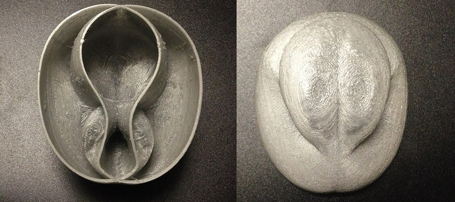
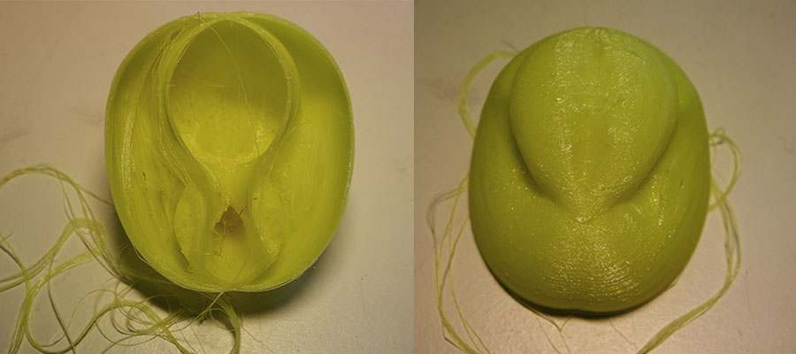
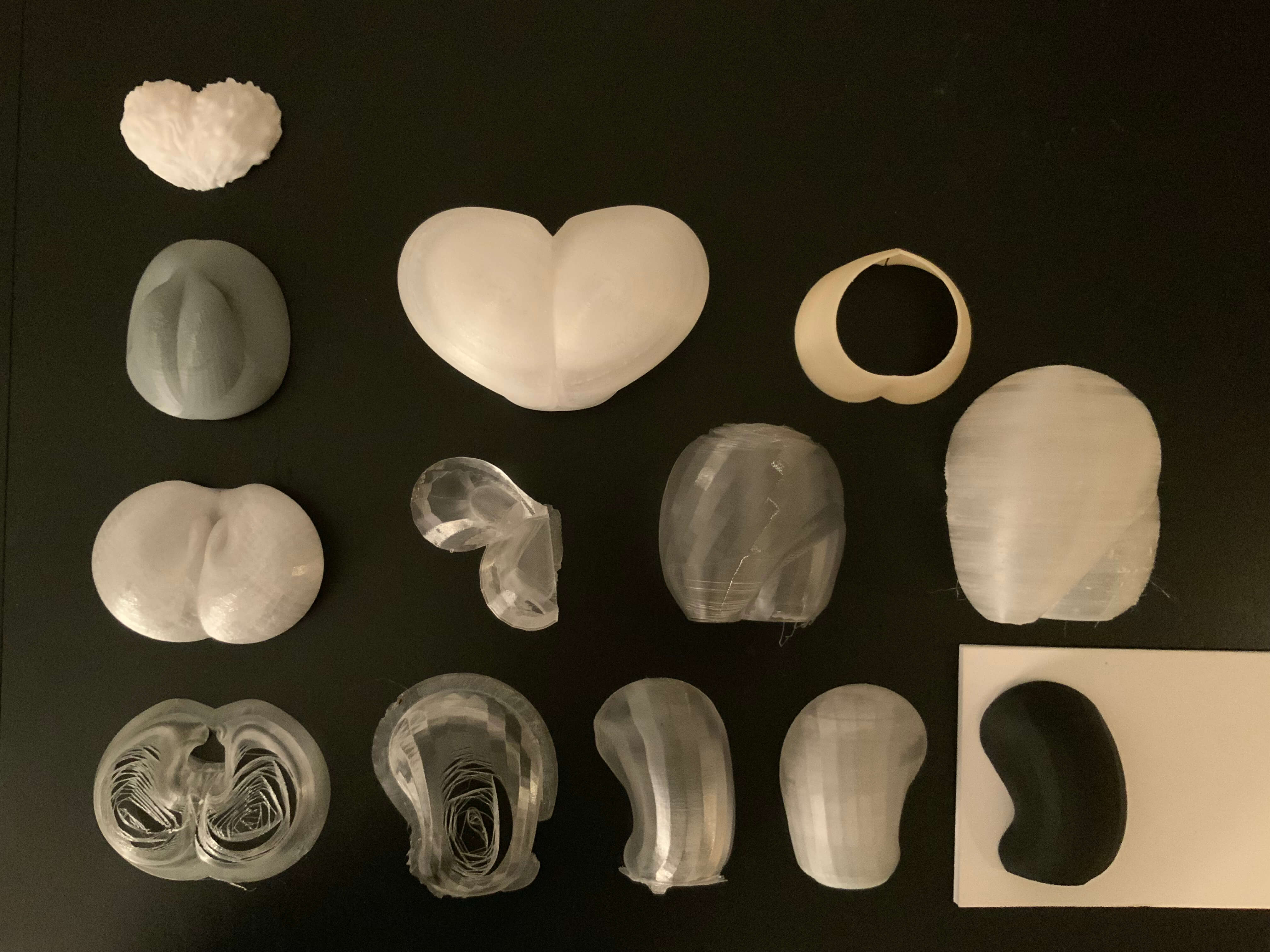
Now the aim is to test and print variations of different enclosure shapes - shells for the light for my final project.
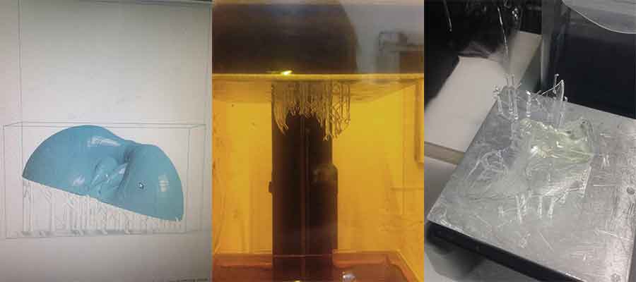
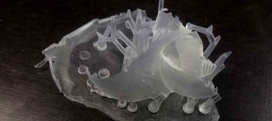
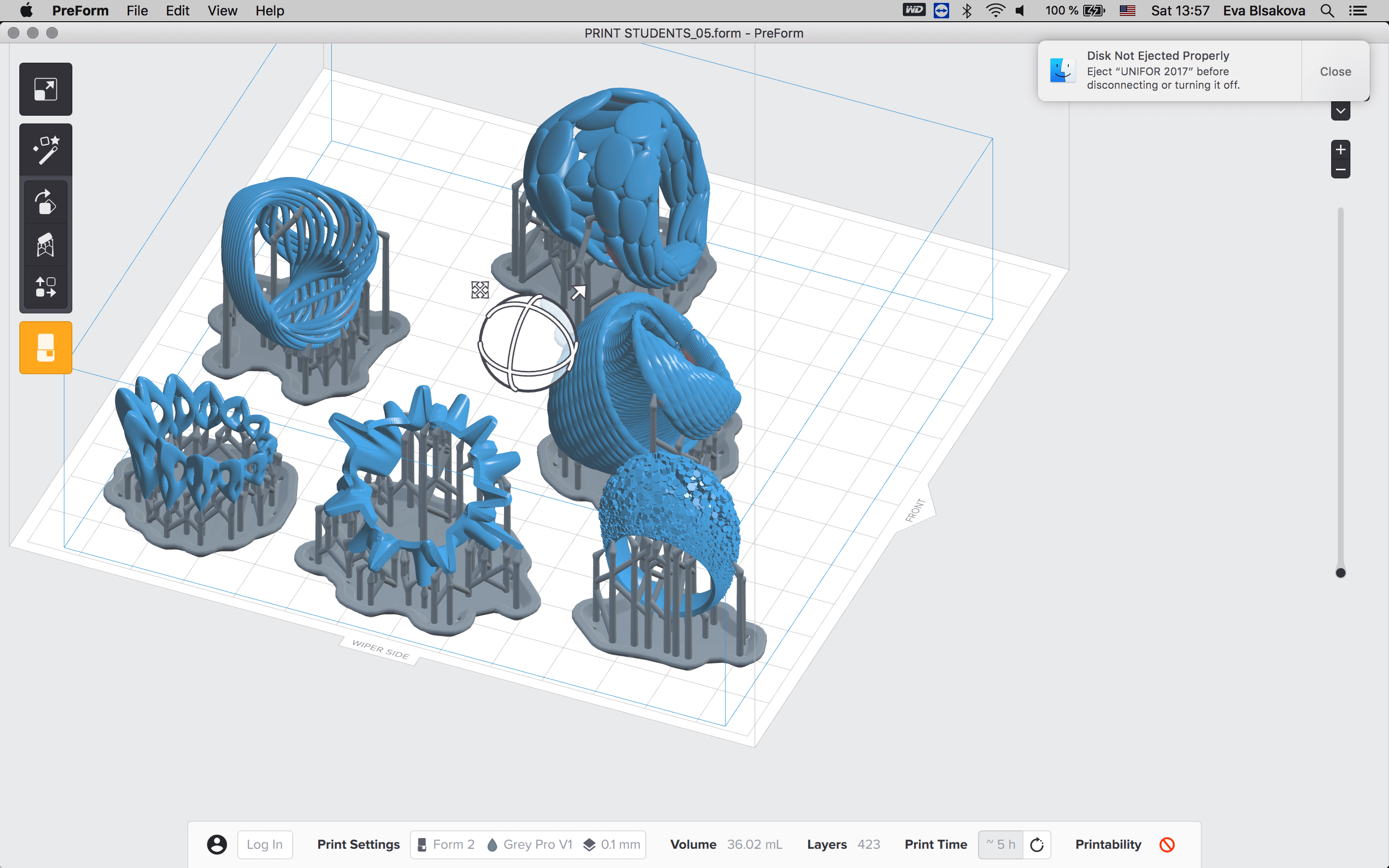
FormLabs - resin printing. images showing slicing sw (PreForm) than piece in the printer and outcome when we just took it out of the printer. still with supports. It was not so succesfull because the printer in the lab is not working properly and has some hardware issues. but I tried...It would be nice to make it in from transparent resin, the qualities of final product would be visually very aestetical in terms of the light conditions interacting with its surface. Anyway, on the picture below you can also see screenshot from PreForm slicer SW what we printed with my students on the Design Morphine Algorithmic Accessories Workshop with Formlabs...was very succesfull and we managed to print a lot of great pieces with this printer. It was the newone Form2.
Than I continued in 2019 with test printing explorations of my final project - lamp shell on various printers available not just in our lab, but also in the IAACs Lab because in the other building they had the possibility to print with zortrax too. pretty simple user interface and the printing process with this machine is very user friendly and straightforward. import stl. choose material, there are already predefined options dedicated to selected materials, than generate the supports if needed and press to print.
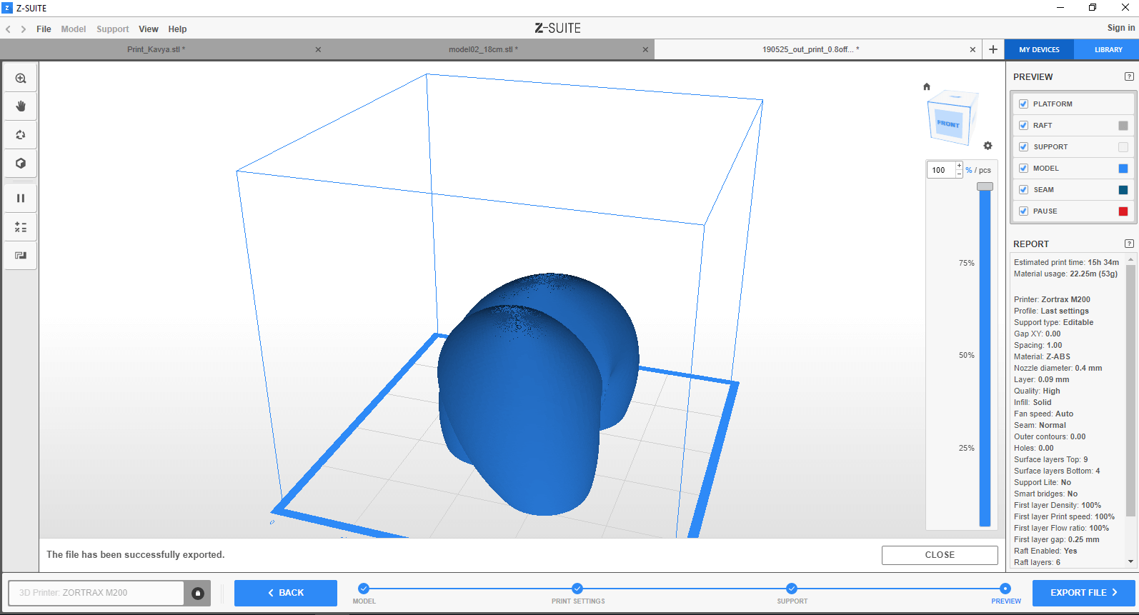
Printing with Zortrax - zGlass material. screenshot of the slicing sw.
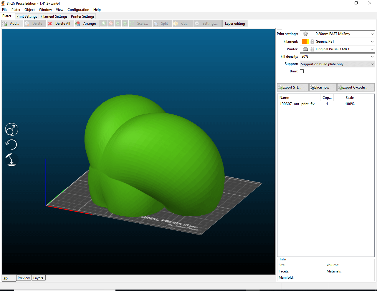
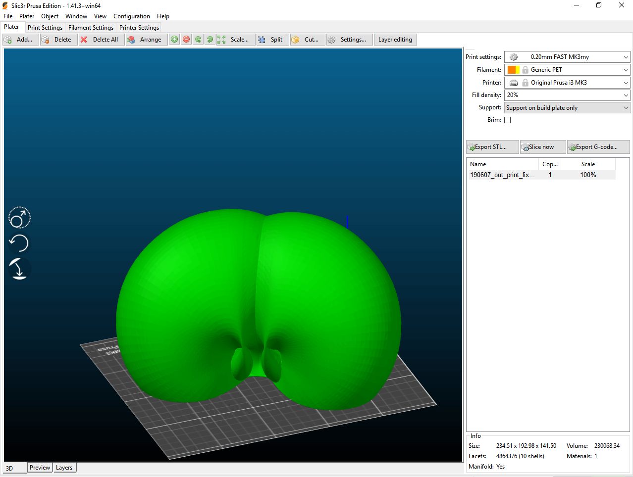
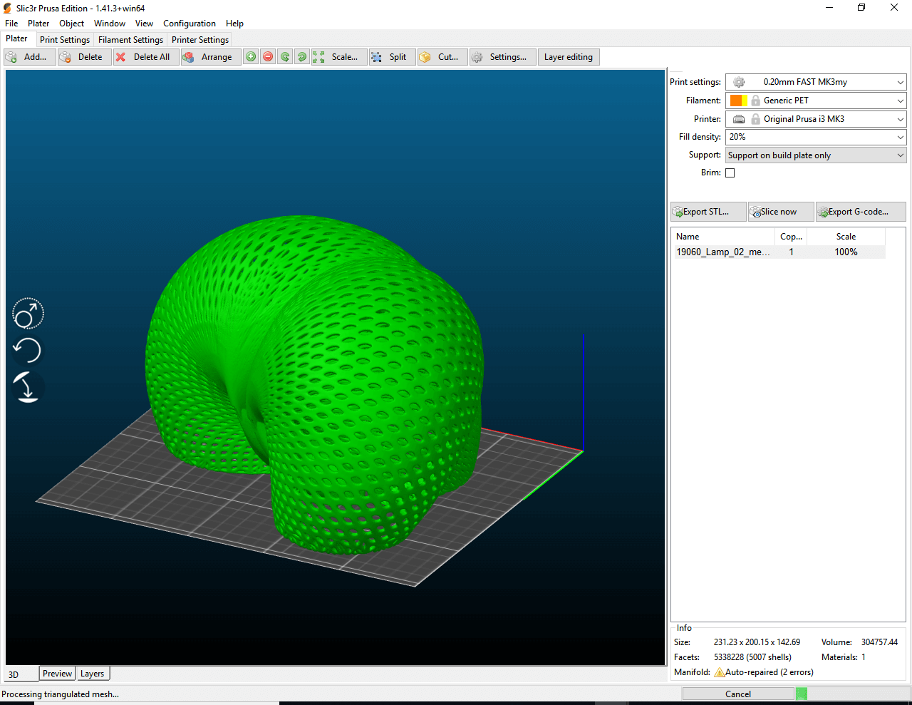
Printing with Prusa - PetG material. screenshot of the slicing sw.
3D printing with different filaments. To get the 3D files ready for printing I exported the Rhino file as .stl file and used Cura to generate the GCode. I cleaned the plate and add lacquer spray to help the print stick to the base. With the SD card in the machine, I navigated through the menu to the print from sd option, select it and clicked ok. The machine starts preheating and the print starts. Cura Settings: * Leyer height: 0.2mm best, 0.3mm and increase temperature for good mechanical properties. * Shell thickness - 2-3mm. * Bottom top - 0.6mm. * Infill - at least 20%. * Print speed - the lower the better definition.
3D printing test using filaflex (elastic filament) with BCN3d RepRap. Filaflex requires a temperature of 230 degrees and speed of 30mm/s. The lower the speed of the print the better; // settings temperature-230/bed temperature-50/ print speed 50.
download files
Download section could be find also here * I made it like that after discussion with our lab instructors due to the large size of .stl files of my complex geometries.
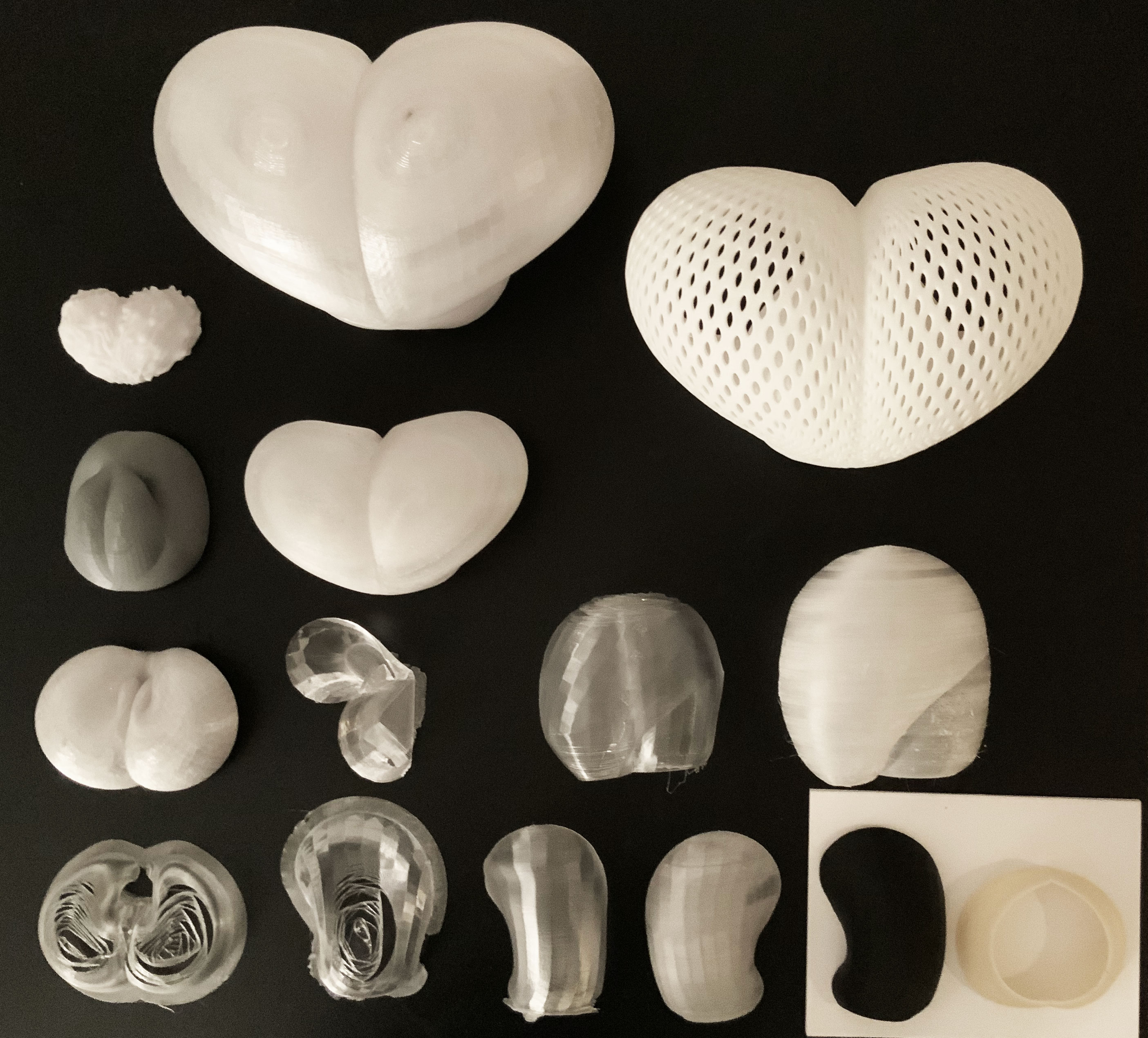
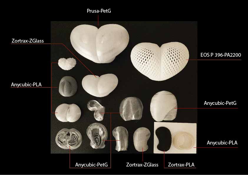
More of my 3D printing experimentation during FabAcademy you can find here. My final project FabLux Smart Interactive Lamp was based on the 3D printing technology exploration - its body was created by this additive manufacturing technique. The final piece was sls 3D printed outside of fab lab Barcelona with this printer:EOS P 396 and material was PA2200.
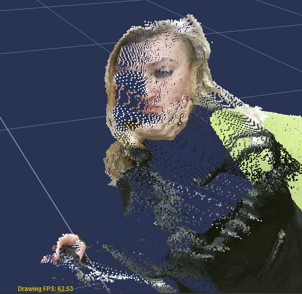
Video of the process of 3D printing and 3D scanning. Machines used: RepRap 3D printers and Modela 3D scanner.
3D scanning experimentation:
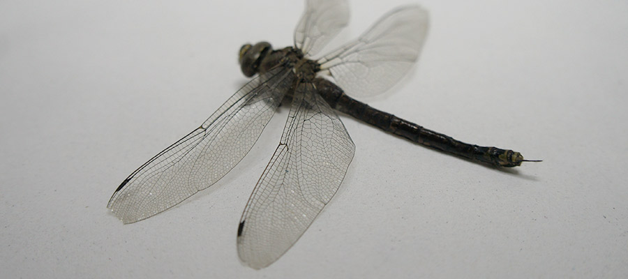
Object to scan - dragonfly. For testing various possibilities with the 3D scanning technology I decided to explore the photogrammetry applied on the capturing of small biological object to explore the results. This dragonfly was found in Valldaura Labs back in 2016.
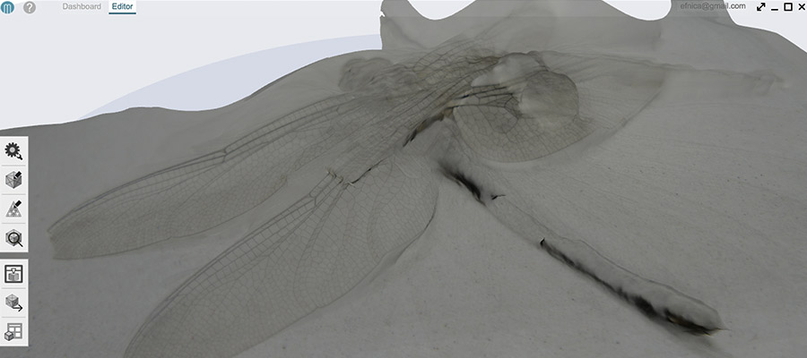
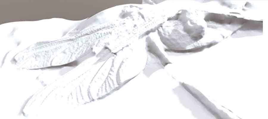
Photogrammetry_free SW Autodesk MEMENTO for creating 3d mesh from photos - “converting any reality capture input (photos, scans) into high resolution 3D digital mesh replicas.” Autodesk Memento was Released as ReMake by ReCap
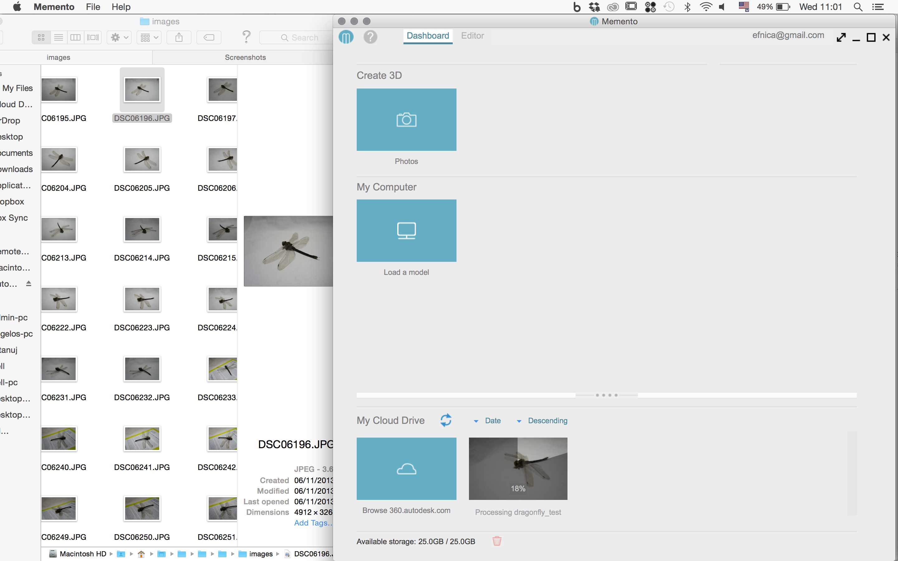
On the right side you can see the source images (I took them with my camera, downloaded them to the computer and loaded those to Memento SW) as an input for the Memento SW - on the left side of the screenshot, processing the dragonfly mesh. Since Autodesk’s cloud-computing resources handle the heavy computing load, this means the software will run on a wide variety of internet-connected devices. I tried to scan also with my iPad to explore posibilities of this 3D scanning environment. I downloaded the app to my iPad, took the pictures directly with the device and processed them to create the 3D mesh. Was just OK. Pros was just because it was processed all in one device.
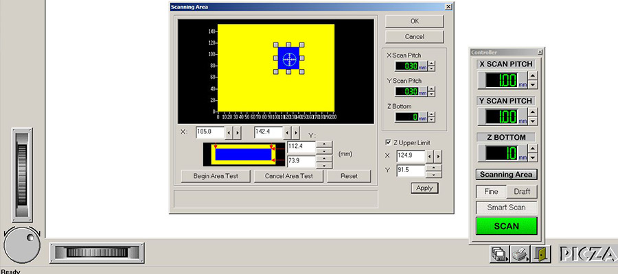

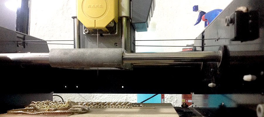
Modela scanning. I placed the butterly figure in the middle of the Modela scanner and secured it with double sided tape. I used the Dr. Picza software (in mm not inches!) to locate object. By moving the handles of the selection square, I fit the selection box as tightly as possible around the butterfly object to minimise scanning time. Double click on boxes of selection area makes the machine move down to determine selection. Measures: x-scan and y-scan: both 0.2 mm (sets resolution) z-scan: 10mm Z upper limit: restricts how high the machine moves over the object, low setting is best to avoid time loss. (tick box; put paper over model; make machine move by hitting apply; machine will move down until it touches the paper = highest model point)
Download 3D scan of dragonfly - test with Memento here
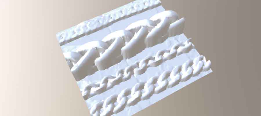
Download 3D scan of chains - test with Modela here