Output Devices

OUTPUT DEIVCE

What is an Output Device?
Output devices in electronic systems transfer energy from the electrical energy that has been processed to another kind of energy, often light, sound or movement (kinetic). Output devices can be digital or analogue. Devices which perform an “Output” function are generally called Actuators.

SERVO MOTORS

What is a Servo Motor?
A servo motor is an electrical device which can push or rotate an object with great precision. If you want to rotate and object at some specific angles or distance, then you use servo motor. It is just made up of simple motor which run through servo mechanism. If motor is used is DC powered then it is called DC servo motor, and if it is AC powered motor then it is called AC servo motor. We can get a very high torque servo motor in a small and light weight packages. Doe to these features they are being used in many applications like toy car, RC helicopters and planes, Robotics, Machine etc.
Servo motors are rated in kg/cm (kilogram per centimeter) most hobby servo motors are rated at 3kg/cm or 6kg/cm or 12kg/cm. This kg/cm tells you how much weight your servo motor can lift at a particular distance. For example: A 6kg/cm Servo motor should be able to lift 6kg if the load is suspended 1cm away from the motors shaft, the greater the distance the lesser the weight carrying capacity.
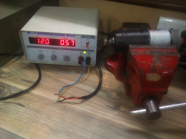
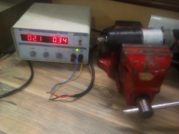
The position of a servo motor is decided by electrical pulse and its circuitry is placed beside the motor

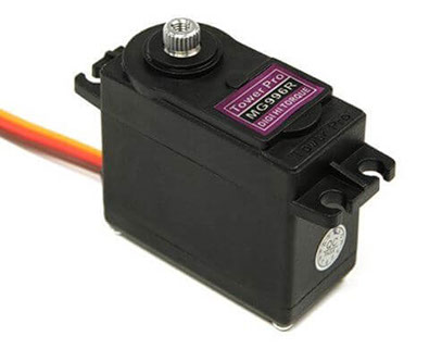
Image and GIF Source~ Google

Working principle of Servo Motors
A servo consists of a Motor (DC or AC), a potentiometer, gear assembly and a controlling circuit. First of all we use gear assembly to reduce RPM and to increase torque of motor. Say at initial position of servo motor shaft, the position of the potentiometer knob is such that there is no electrical signal generated at the output port of the potentiometer. Now an electrical signal is given to another input terminal of the error detector amplifier. Now difference between these two signals, one comes from potentiometer and another comes from other source, will be processed in feedback mechanism and output will be provided in term of error signal. This error signal acts as the input for motor and motor starts rotating. Now motor shaft is connected with potentiometer and as motor rotates so the potentiometer and it will generate a signal. So as the potentiometer’s angular position changes, its output feedback signal changes. After sometime the position of potentiometer reaches at a position that the output of potentiometer is same as external signal provided. At this condition, there will be no output signal from the amplifier to the motor input as there is no difference between external applied signal and the signal generated at potentiometer, and in this situation motor stops rotating.

Controlling Servo Motor: All motors have three wires coming out of them. Out of which two will be used for Supply (positive and negative) and one will be used for the signal that is to be sent from the MCU.
Servo motor is controlled by PWM (Pulse with Modulation) which is provided by the control wires. There is a minimum pulse, a maximum pulse and a repetition rate. Servo motor can turn 90 degree from either direction form its neutral position. The servo motor expects to see a pulse every 20 milliseconds (ms) and the length of the pulse will determine how far the motor turns. For example, a 1.5ms pulse will make the motor turn to the 90° position, such as if pulse is shorter than 1.5ms shaft moves to 0° and if it is longer than 1.5ms than it will turn the servo to 180°.
Servo motor works on PWM (Pulse width modulation) principle, means its angle of rotation is controlled by the duration of applied pulse to its Control PIN. Basically servo motor is made up of DC motor which is controlled by a variable resistor (potentiometer) and some gears. High speed force of DC motor is converted into torque by Gears. We know that WORK= FORCE X DISTANCE, in DC motor Force is less and distance (speed) is high and in Servo, force is High and distance is less. Potentiometer is connected to the output shaft of the Servo, to calculate the angle and stop the DC motor on required angle.

Servo motor can be rotated from 0 to 180 degree, but it can go up to 210 degree, depending on the manufacturing. This degree of rotation can be controlled by applying the Electrical Pulse of proper width, to its Control pin. Servo checks the pulse in every 20 milliseconds. Pulse of 1 ms (1 millisecond) width can rotate servo to 0 degree, 1.5ms can rotate to 90 degree (neutral position) and 2 ms pulse can rotate it to 180 degree.
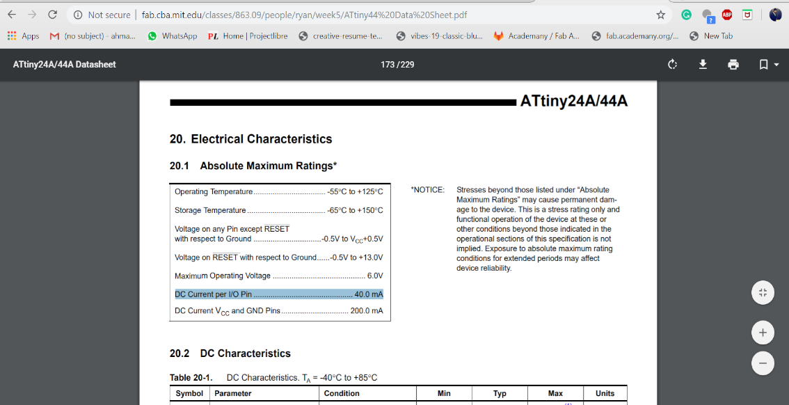
All servo motors work directly with your +5V supply rails but we have to be careful on the amount of current the motor would consumes.

https://circuitdigest.com/article/servo-motor-basics

I decided to make a board having servo motor. I referred Neil’s board for making my board using ATTiny 44. Components I used

  • ZLDO117 Voltage Regulator
  • AVRISP
  • Capacitor
  • Resistor
  • 2 - 6 pin headers for servo motor

Designing In Eagle


Now routing for the board


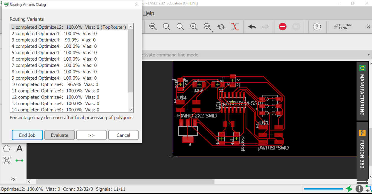
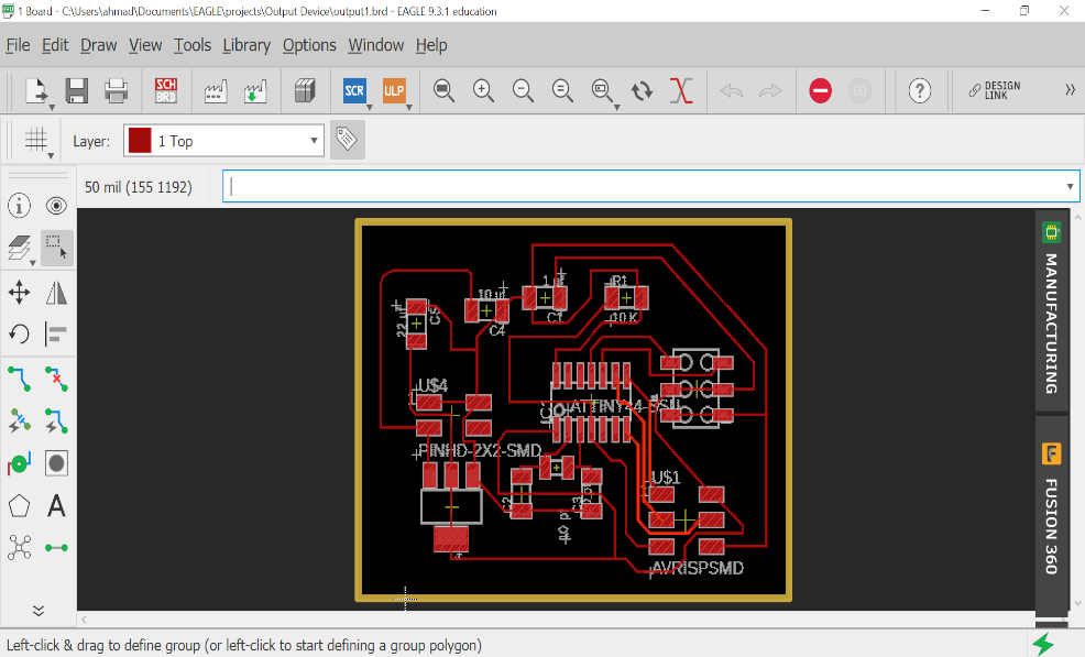
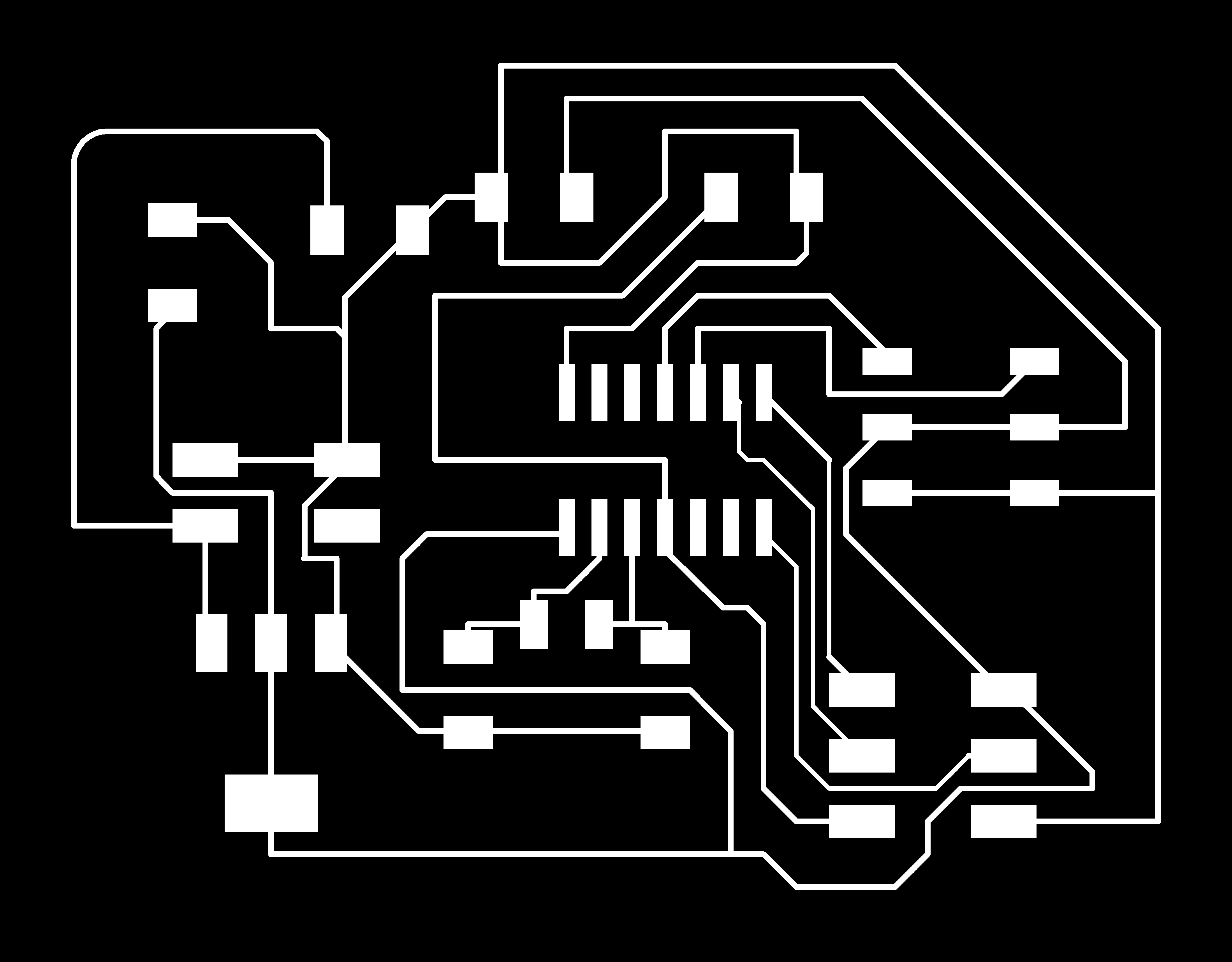
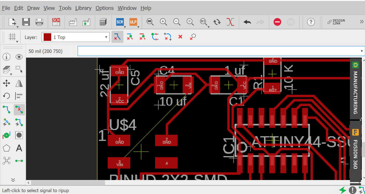
Still did some manual routing beacause autorouting feature does some excess turns in the paths.


Download all the above files from here

traces
Traces
outline
Cutout- need to invert the image in fabmods to generate toolpath

Using Fabmods to generate tool path


Issues

Firstly I tried to iterate Neils board so it has ZLDO 1117 IC and in our Lab we had LMS117 the output volatages differ in in them as the latter is 3.3v so I decide to give it a power supply.

Major Issues
The Servo didn't work!!!
It was getting some power but the sweep code was not working, then I read the datasheet and google a bit about IO of Tiny45 and it came to know that it provide max current of 40mA and our servo required atleast 100mA.

I gave it an external supply from the power supply we had at LAB but still it didn't work. Howerver I thought that giving it the external supply will cover it's current requirement and oonly the data will be triggered using the data pin from the board I milled.
Yes I common the ground of the supply and the board which was the mistake I was doing intitailly, also I changed the servo thinking the servo I was using was wornout or something but that was agian not the case. I checked for the volage level at the output of the dat line and the vcc and gnd lines all was working fine.
After scratching a lot of head over the servo I decided to use the neopixel LED as the output device, which was going to be as the output device for my final project too.

The Code


                        #include < Servo.h>

                        Servo myservo;  // create servo object to control a servo
                        // twelve servo objects can be created on most boards

                        int pos = 0;    // variable to store the servo position

                        void setup() {
                          myservo.attach(9);  // attaches the servo on pin 9 to the servo object
                        }

                        void loop() {
                          for (pos = 0; pos <= 180; pos += 1) { // goes from 0 degrees to 180 degrees
                            // in steps of 1 degree
                            myservo.write(pos);              // tell servo to go to position in variable 'pos'
                            delay(15);                       // waits 15ms for the servo to reach the position
                          }
                          for (pos = 180; pos >= 0; pos -= 1) { // goes from 180 degrees to 0 degrees
                            myservo.write(pos);              // tell servo to go to position in variable 'pos'
                            delay(15);                       // waits 15ms for the servo to reach the position
                          }
                        }
                    

Output Device Servo-failed from Ahmad Ali on Vimeo.


Then I decided to use my neopixel LED which I was going to use for the output of my final Project..

What is Neopixel LED

The neopixel LED's are individually addressable RGB LED's which can be controlled by a ingle data pin.
They come in 12v or 5V supply it has 3 Lines vcc,gnd,data...The data is that data what the controller feeds to it.
When compared to a normal RGB LED we need 3 pins to control the Red Green and Blue value and all LEDs have to either on or off. Using these individually addressable can help create some very cool effects.
Lots of companies sell strips of addressable LEDs however the most popular is the NeoPxiel by Adafruit. Adafruit produces a line of addressable LED strip and also supplies the library to control them, this is called "Adafruit NeoPixel" that give various inbuilt example codes to play with the strip of LED's.
I downloaded the Adafruit Neopixel Library from this link https://github.com/adafruit/Adafruit_NeoPixel
After That I opened Arduino and added the library and opened the simple example and try to upload since the code was too big and it occupied most of the space of AtTinty45, I needed to modify the code for less number of LEDs and reduce the line of code to reduce the size.
So i decided to turn all the 6 LeD's with different colors, for understanding the function and how the neopixel LED code's work there is some good documentation on the instructables I refered this blog and understood most of it-
https://www.instructables.com/id/Neopixels-How-Do-They-Work/


And yes it worked...but it did not work on the example code of the strand as the code was taking alot more memory

I optimize the code because any by default examples were not working as 45 as a very less memory, so I use only 5 led so that the curent drawn will be less.
                                    #include < Adafruit_NeoPixel.h>
                                                    #ifdef __AVR__
                                                     #include < avr/power.h>
                                                    #endif
                                                    #define PIN 3//data pin of led attached to the pin of the board
                                                    #define NUM_LEDS 6//Number of individual LED's
                                                    int i=0;
                                                    //create a NeoPixel strip
                                                    Adafruit_NeoPixel strip = Adafruit_NeoPixel(NUM_LEDS, PIN, NEO_GRB + NEO_KHZ800);


                                                    void setup() {
                                                      strip.begin();
                                                      strip.show();
                                                    }

                                                    void loop()
                                                    {
                                                    strip.setPixelColor(0,0,0,255);//0 led on 
                                                    strip.setPixelColor(1,255,0,0);//1st led on
                                                    strip.setPixelColor(2,0,255,0);//2nd led on  //Turning all the 6 LED's On with different color
                                                    strip.setPixelColor(3,255,0,0);//3rd led on
                                                    strip.setPixelColor(4,0,255,0);//4th led on
                                                    strip.setPixelColor(5,255,255,0);//5th led on
                                                    strip.setPixelColor(6,0,255,255);//6th led on
                                                    strip.show();
                                                    delay(1000);
                                                    for(i=0;i<6;i++)// Setting up the loop that goes till 6th led 
                                                    {
                                                      strip.setPixelColor(i,0,0,0);//The i in this is that particular numbered  LED 
                                                      strip.show();
                                                      delay(500);// a delay of 500 milliseconds
                                                    }
                                                  

                                                    }


RGB test from Ahmad Ali on Vimeo.


Group Work -

Visit our Lab Group page. This week our group assignment was to measure power consumption of an output device. To do so we decided to measure power of a motor.We Connected a Planetery Geared DC Motor to a Variable power supply and observed the current drawn by the motor.


Observations
  • It may be noticed that the current drawn by the motor @ 2.1 V is about 340mA, and the current drawn by motor @ 12 V is about 570mA.
  • So the Power consumption Using formula P=VI where P = Power, V = voltage and I = Current
  • P = 0.340 * 2.1 = 0.714 Watt
  • P = 0.570 * 12 = 6.84 Watt
  • So the power consumed by motor at No load ranges from 0.714 Watts - 6.84 Watts

Learning

Top