Input Devices

What is an Input Device?

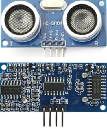
An input device is an equipment/Component used to provide data and control signals to an information processing system such as a Micro Controller. Examples of input devices include Sensors, Cameras etc.

Sensors & Transducers

A sensor is a transducer whose purpose is to detect some characteristic of its environments. It detects events or changes in quantities and provides a corresponding output, generally as an electrical or optical signal. Transducers are measurement devices used to change one kind of energy to another. Energy may include electrical, mechanical, electromagnetic, chemical, acoustic, and thermal energy
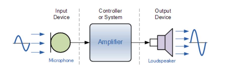
Devices which perform an "Input" function are commonly called Sensors because they "sense" a physical change in some characteristic that changes in response to some excitation, for example, heat or force and convert that into an electrical signal. Devices which perform an "Output" function are generally called Actuators and are used to control some external device, for example, movement or sound.

Analogue and Digital Sensors

Analogue Sensors
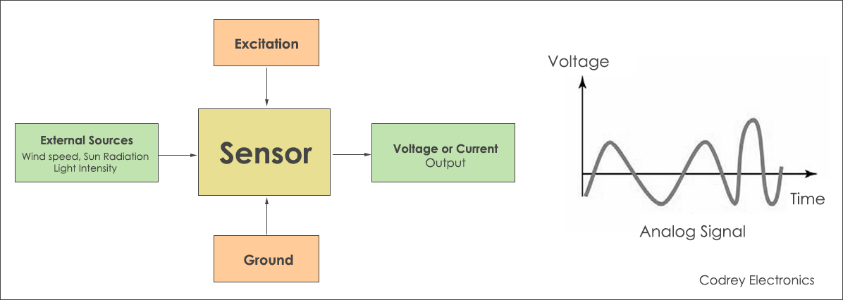
Analog Sensors produce a continuous output signal or voltage which is generally proportional to the quantity being measured. Physical quantities such as Temperature, Speed, Pressure, Displacement, Strain etc are all analog quantities as they tend to be continuous in nature. For example, the temperature of a liquid can be measured using a thermometer or thermocouple which continuously responds to temperature changes as the liquid is heated up or cooled down.

Digital Sensors
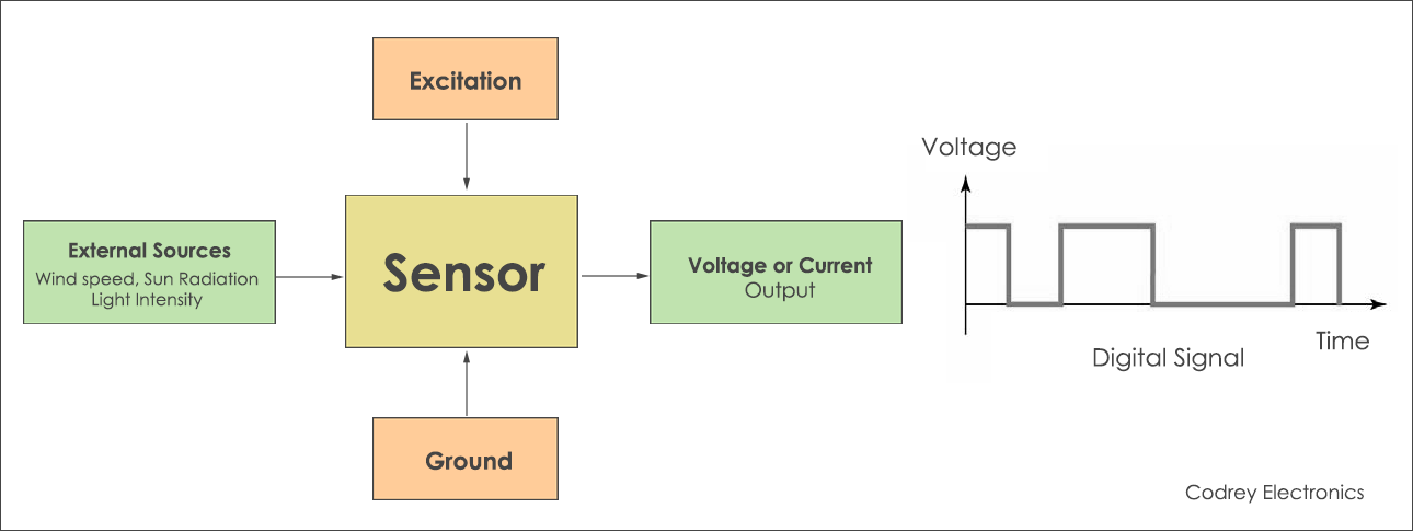
As its name implies, Digital Sensors produce a discrete digital output signals or voltages that are a digital representation of the quantity being measured. Digital sensors produce a Binary output signal in the form of a logic “1” or a logic “0”, (“ON” or “OFF”). This means then that a digital signal only produces discrete (non-continuous) values which may be outputted as a single “bit”, (serial transmission) or by combining the bits to produce a single “byte” output (parallel transmission).

Source www.codrey.com/electronics/different-types-of-sensors

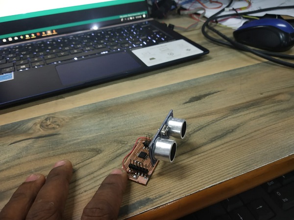
Sensors/Input Devices from my Learning-

What a sensor basically does is, it takes the physical change or mesures the physical change and convert that change into some voltage, that voltage undergoes some changes like may be it can be amplified or may be not,
After that there is some mathematical relation, the voltage values are raw it's not a data its fed into some function whose output is the valuable data that we the user actually want from the sensor.
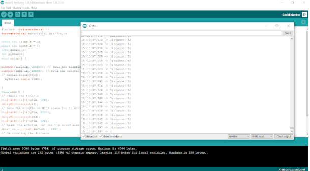
How it's performed
There are various libraries for various sensors, the libraries are nothing but some line of codes which include some fucntions, from which we call those predefined functions to make our main code easy and simple. The library files mostly includes all the conversion formula from which we get the output data from the sensor.
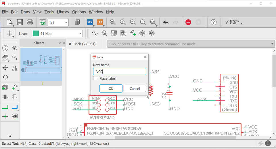
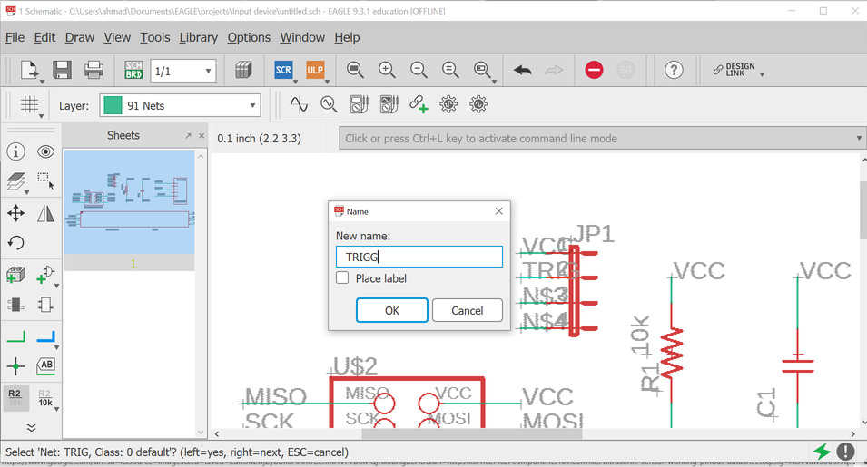
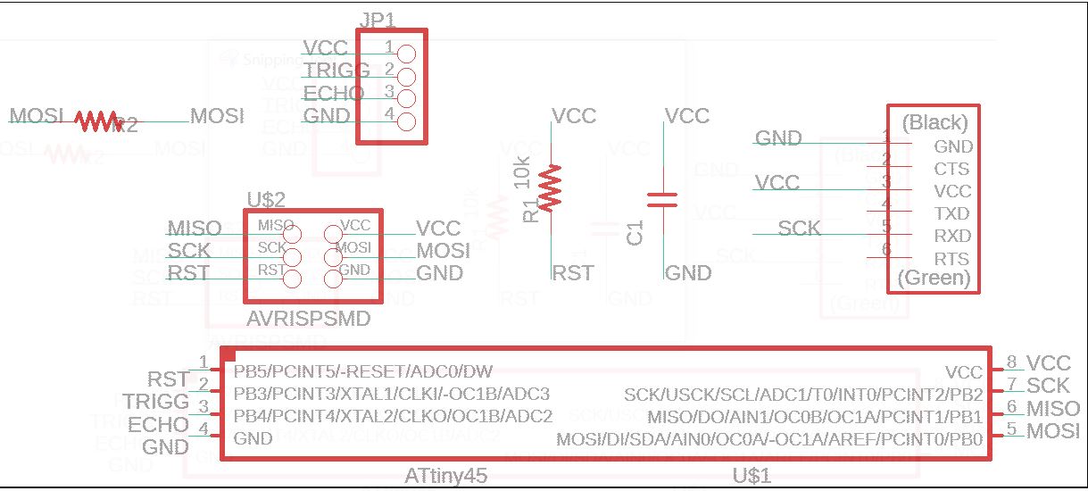
My Input Devices

HCSR04- Ultrasonic sensor

The HC-SR04 ultrasonic sensor uses sonar to determine distance to an object like bats do. It offers excellent non-contact range detection with high accuracy and stable readings in an easy-to-use package. It comes complete with ultrasonic transmitter and receiver modules


How Does it Work?

The ultrasonic sensor uses sonar to determine the distance to an object. Here’s what happens:

  • The transmitter (trig pin) sends a signal: a high-frequency sound.
  • When the signal finds an object, it is reflected and…
  • The transmitter (echo pin) receives it.


The time between the transmission and reception of the signal allows us to calculate the distance to an object. This is possible because we know the sound’s velocity in the air.

HC-SR04 Ultrasonic Sensor Pinout

Pins

  • VCC: +5VDC
  • Trig : Trigger (INPUT)
  • Echo: Echo (OUTPUT)
  • GND: GND

Features and specs:

  • Dimension: 45mm x 20mm x 15mm
  • Power Supply :+5V DC
  • Quiescent Current : <2mA
  • Working Current: 15mA
  • Effectual Angle: <15°
  • Ranging Distance : 2cm – 400 cm/1″ – 13ft
  • Resolution : 0.3 cm
  • Measuring Angle: 30 degree st
  • Trigger Input Pulse width: 10uS
Source~ https://randomnerdtutorials.com/complete-guide-for-ultrasonic-sensor-hc-sr04/


Designing In Eagle


The final schematic
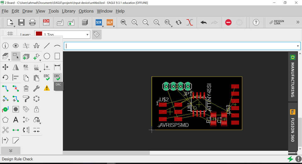
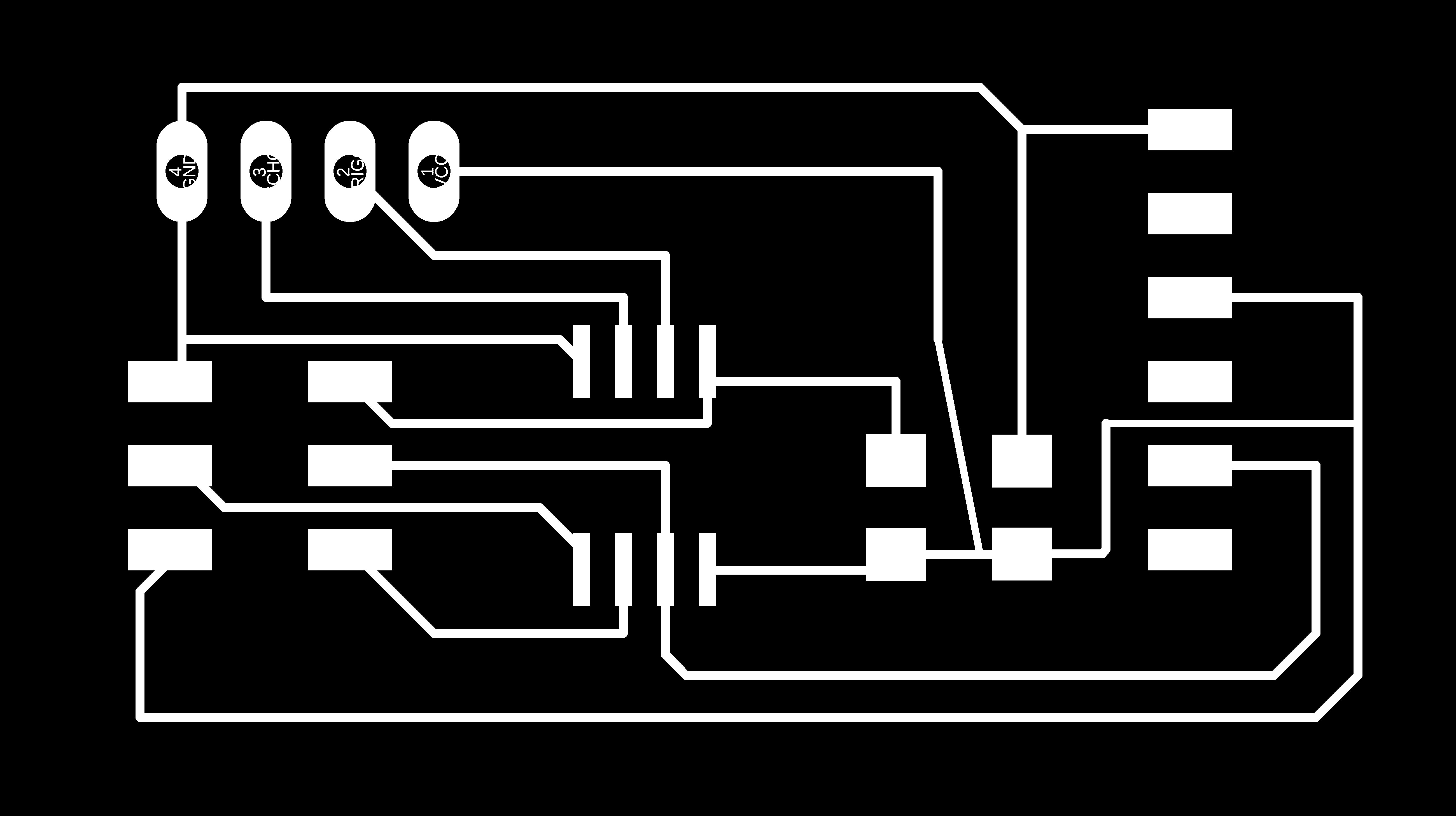
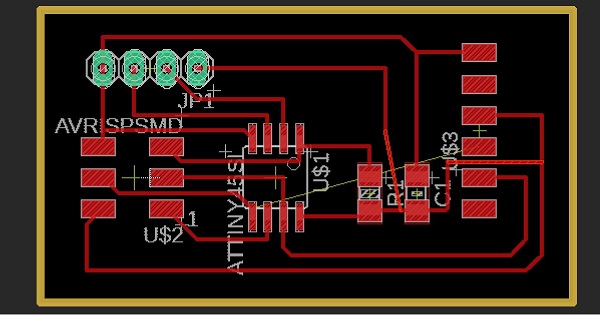
The final Board layout


cutout
The trace file-

Using FabModules to generates toolpath


SRM in Action


Slodering and programming


Issues

While making the board I forgot to add the Rx pin for the Ftdi to see the values on Serial monitor so I had to plug a jumper because I wanted to make the board working and not to mill another one.
The code-
                                                

                                                 #include < SoftwareSerial.h >
                                                    SoftwareSerial mySerial(0, 2);//rx,tx 

                                                    const int trigPin = 3;
                                                    const int echoPin = 4;
                                                    long duration;
                                                    int distance;
                                                    void setup() {
                                                      
                                                    pinMode(trigPin, OUTPUT); // Sets the trigPin as an Output
                                                    pinMode(echoPin, INPUT); // Sets the echoPin as an Input
                                                    // Serial.begin(9600);
                                                      mySerial.begin(9600);

                                                    }
                                                    void loop() {
                                                    // Clears the trigPin
                                                    digitalWrite(trigPin, LOW);
                                                    delayMicroseconds(2);
                                                    // Sets the trigPin on HIGH state for 10 micro seconds
                                                    digitalWrite(trigPin, HIGH);
                                                    delayMicroseconds(10);
                                                    digitalWrite(trigPin, LOW);
                                                    // Reads the echoPin, returns the sound wave travel time in microseconds
                                                    duration = pulseIn(echoPin, HIGH);
                                                    // Calculating the distance
                                                    distance= duration*0.034/2;
                                                    // Prints the distance on the Serial Monitor
                                                    mySerial.print("Distance: ");
                                                    mySerial.println(distance);
                                                    }


Download all the above files from here

The Output

Input from Ahmad Ali on Vimeo.


Group Assignment

For the group page of this week visit Our Group Page.

About Oscilloscopes

One needs to understand the circuits on signal level, which multimeters fails to do. In this case Oscilloscopes is the answer. A digital oscilloscope measures the signal, and then converts that measurement into a digital format using an ADC converter, after which the data measured is depicted as a digital waveform representation. From this representation various paramters can be evaluated. In our lab we got Scientific SMO1102E and Keysight DSO1052B Oscilloscopes.

Key Features

  • Bandwidth = 50 MHz
  • Channels = 2
  • Max Memory Depth = 16 kpts
  • Max Sample Rate = 1 GSa/s
  • Display Size = 5.7 inch
  • ADC Bits = 8 bits
  • USB storage, RS232C and J45 interface
  • Multi-waveforms math, FFT Function
  • Built-in delay sweep function
  • Waveform Record and Recall, Trigger Mode for Edge, Video, Pulse Width, Slope and Alternate
https://in.element14.com/keysight-technologies/dso1052b/oscilloscope-2ch-50mhz-1gsps/dp/2094428

Measuring Signals

Measuring Digital Signals

we tested out the crystal on an Arduino UNO, we connected the probes to the crystal of Ardunio Uno which showed a frequency of 16 MHz.
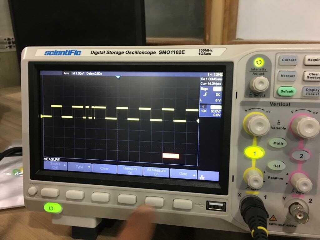
We then uploaded Blink code on the UNO board and we observed the pulse signal.

Measuring Analog Signals

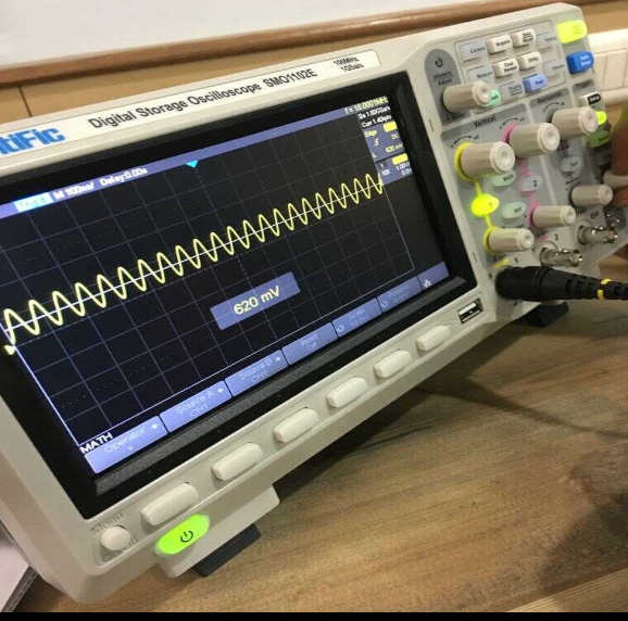
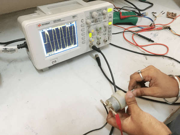
For measuring the analog signals, We connected both the terminals for the motors with the probes of the DSO and then we rotated the motor shaft manually.

Learning/Observations from group Assignment

  • On the DSO Screen, It may be noticed that digital pulses with a time gap of 1 seconds were observed with peak value of voltage of 5V.
  • Also it was obeserved that the pulses were smooth, as we caliberated the probes earlier as showcased in video
  • Analog signal was clearly visualized on the DSO Screen.(An Analog signal is any continous signal for which the time varying feature (variable) of the signal is a representation of some other time varying signal i.e analogous to another time varying signal, This is also the reason why wave form is rising up and down with time.)
  • DSO was measuring voltage w.r.t Time and A peak voltage of about +10V was observed. When the motor shaft direction is reversed the signal also changes the ploarity and a reverse peak voltage of about -8V was observed


Overall Learning

Top