This week we had to design, make and program a board that lets us use an input to read something. Since I will be controlling temperature in my final project I selected the NTC Thermistor example to adapt.
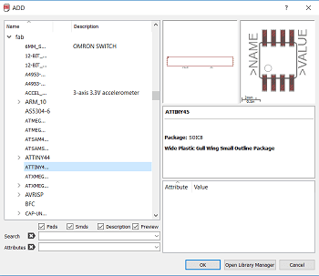
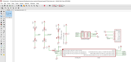
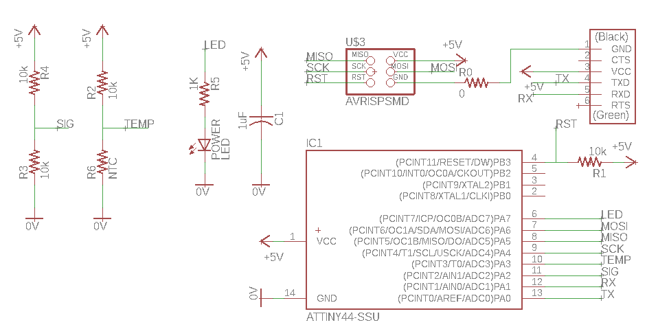
Next I opened up my Eagle and started adding the components from the example plus a 1k resistor and a LED to show me if the board has power.
Following I connected my components in my schematic.
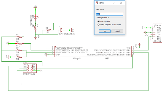
I changed some of the paths names in order to make it easier to finish my schematic.
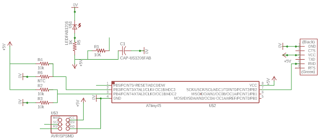
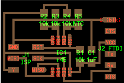
Once I finished my schematic I started with my board design.
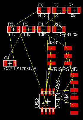
I had to try a couple of times and move things around.(Not an expert on Eagle yet)
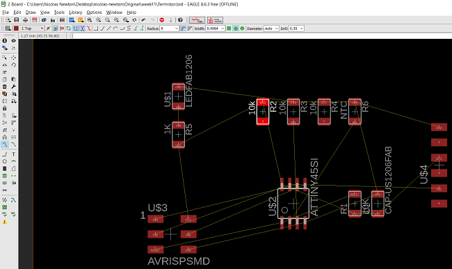
Finally, I finished (or so I thought) routing after about 2 hours trying.
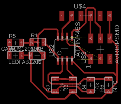
I moved things around to make my board more space efficient.
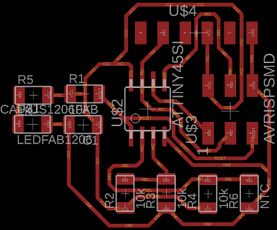
Later while trying to program my board I found out there wasa problem, my LED was turning on but my laptop wasn't recognizing the microcontroller so I deviced a way to check my schematics convinced I may have overlooked something.
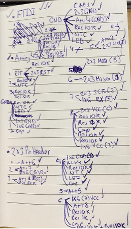
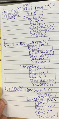
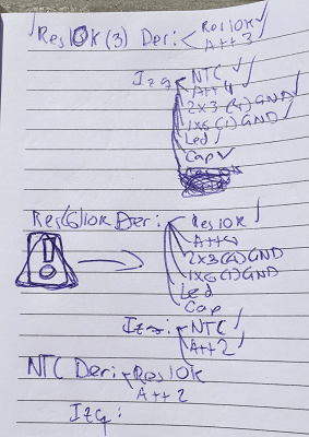
I found the problem after about an hour checking every route on the board! By mistake I connected my NTC to ground and the ground was connecting to my Attiny's 4th pin.(From datasheet pinout).
I quickly got to designing a new route to get back on track. This time I was quicker and more efficient.
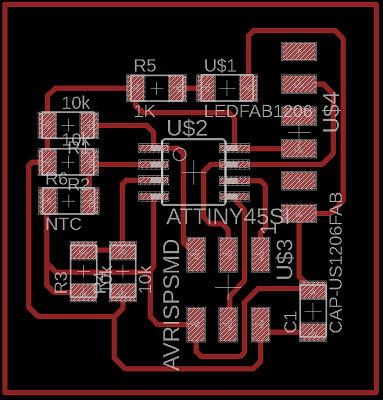
My new board was more space efficient and had no routing errors.
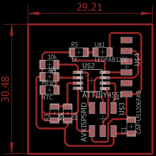
After I finished, my board was being recognized but I had trouble uploading Neil's code with windows 10 so I decided to make another board with an LED I could use to show I was reading the temperature. These are versions 1 and 2 of my second board:
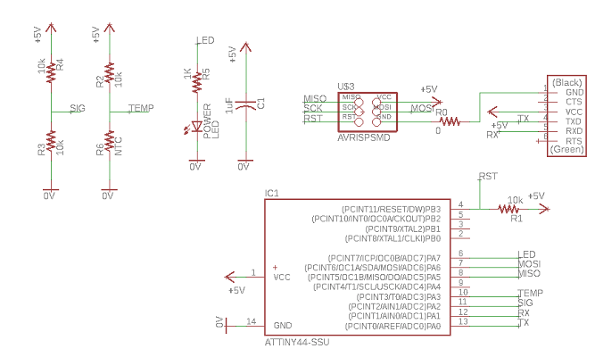
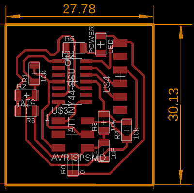
I forgot to route the SCK pin from the attiny44 to the ISP 2x3 header so I made version 2 with a minor alteration
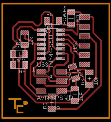
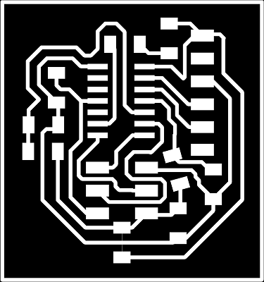
First, I exported the monochrome PNG.
This came out.
My adaptation of Neil's board.
I inserted my input board's monochrome into Fab Modules and got my G-Code file.
My adaptation of Neil's board.
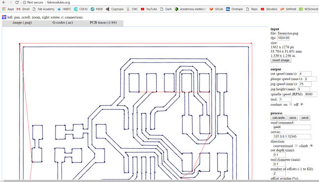
My board's 2nd version.
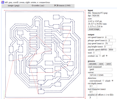
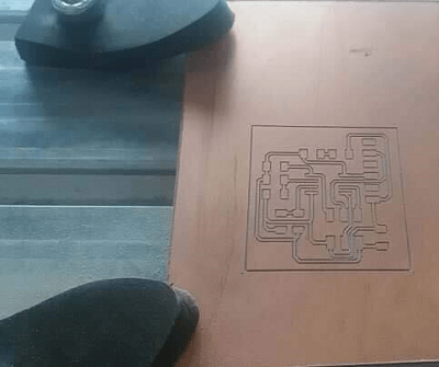
Next I inserted it into the Modela router and milled it exactly as I milled my boards from week 5, 7 and 9.
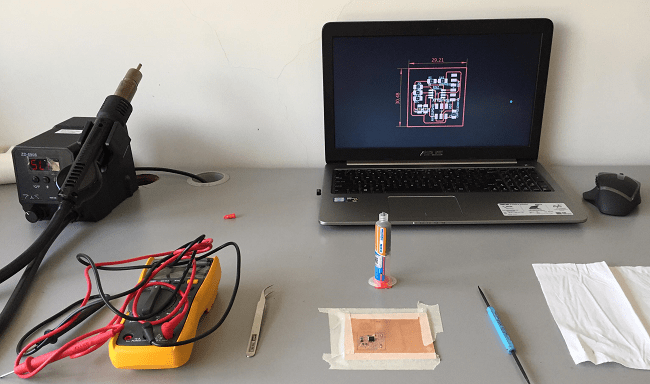
Initially I set up my soldering station.
And I started soldering with Flux, I've gotten much more proficient using it with practice(Almost no mistakes per board, its been 3 boards without having to re-solder anything).
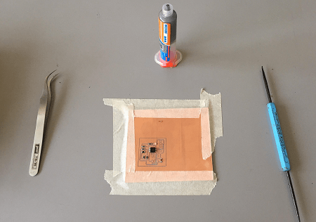
Quickly my board started looking more like a finished product.
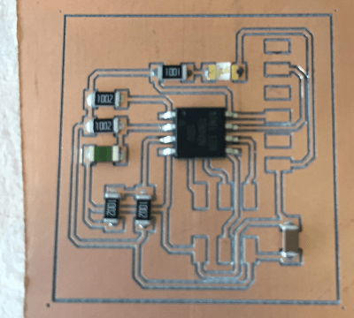
Almost done...
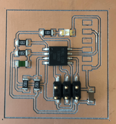
A couple minutes more and I was finished!
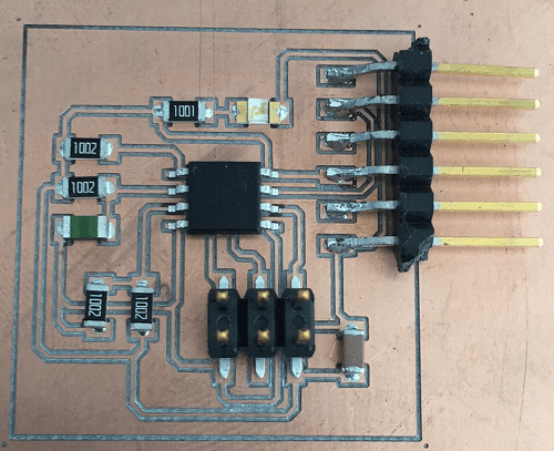
Final version of the second board.
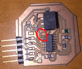
Just like the other weeks involving programming I started by trying to burn my attiny's bootloader. I connected my board with an AVR MKII programmer.
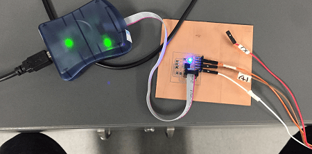
Next I selected the right board, port and programmer.
Having selected everything I attempted to burn my bootloader.
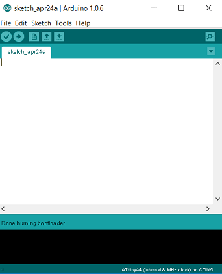
Miraculously it worked!!! There was just one issue, my board had no legs left to use the SerialMonitor software for arduino and the Attiny45 doesn't have the option of using the serial monitor so I was stuck.
I went to the Fab Archive for resources on how to tackle this problem and found out Neil had done a C code to get around this so I got to researching how to use it as I am not an expert in C.
After several days trying to make my computer compile Neil's code I decided to start a new board using an attiny44 and an extra LED. This is how I programmed it.
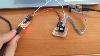
This time I was trying with my FTDI and my fabISP from Electronics production. Next I burnt the bootloader.
And uploaded my code making the LED blink if the temperature was above 20 degrees celsius.
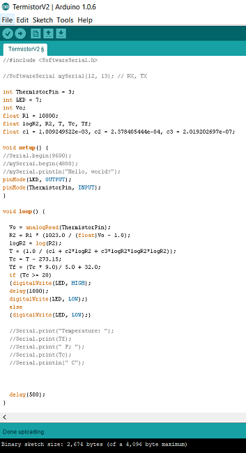
Finally, I modified it so that the LED would stop blinking if the temperature wasn't between 20-23 degrees celsius.
Here is a video of the board working.
Download the original files from the links below:
Termistor Schematic Final Version: Eagle (.sch file)
Termistor Board Final Version: Eagle (.brd file)
Termistor G-Code Final Version: FabModules (.nc file)
Termistor Code Final Version: Arduino (.ino file)