This week we had to design, make and program a board with an output we can control, since I'm gonna use a DC Motor for my extruder I opted to have that as my output. I started by looking at Neil's board.
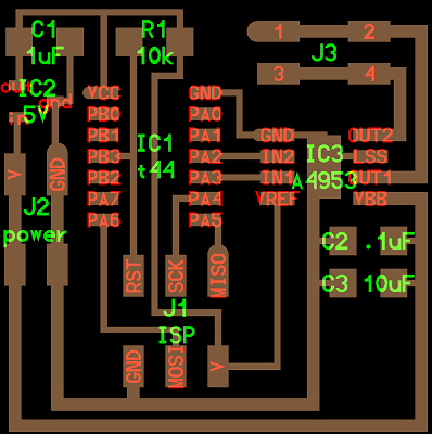
I wanted to add both a LED to be able to show programming skills for week 9 and a LED to show when the board is powered.
First, I downloaded the allegro-2 library for my eagle to have more component choices.

Second, I added the components I was to use.
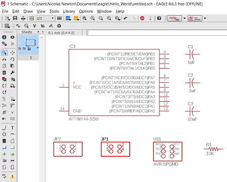
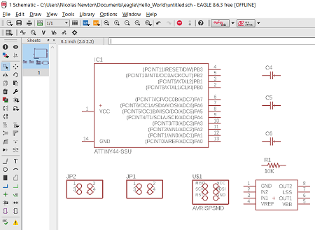
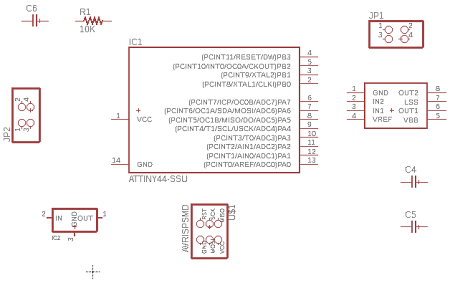
Next, I connected the paths, changed the names of some paths and checked for errors in my schematic.
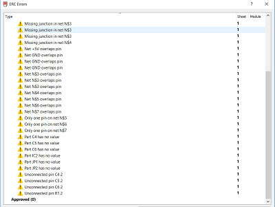
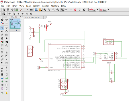
After a couple more components and connections my schematic was done.
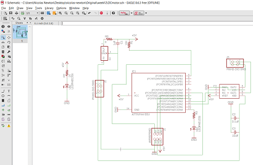
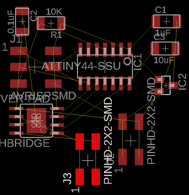
It was time to start routing
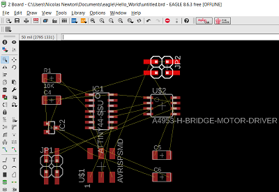
When I start I like trying auto-route to get a general idea of where my components should be although its not as easy as it sounds.
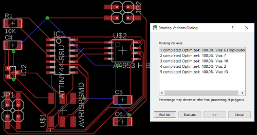
After I moved my components around and tried routing and checked for errors (Aside from the missing routes everything seemed ok).
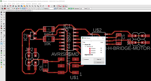
I couldnt connect all the paths. D:
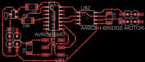
So I started again.
This time I managed by using a 0 ohms resistor bridge.
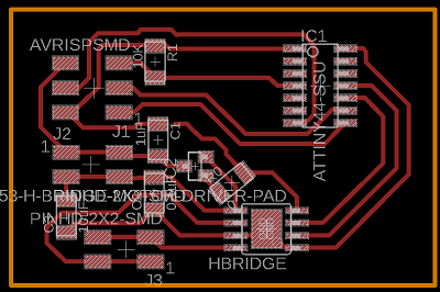
I optimized the space used and this was the result!

I exported the monochrome png image of my design.
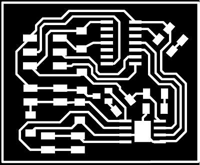
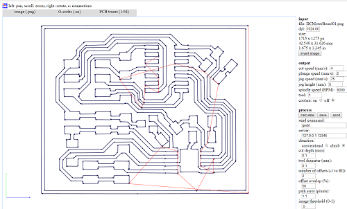
After I inserted the monochrome into FabModules to get my G-Code file (.nc).
Using the Modela I milled my board and started soldering.
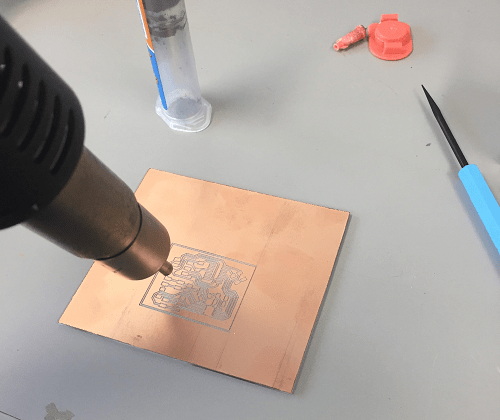
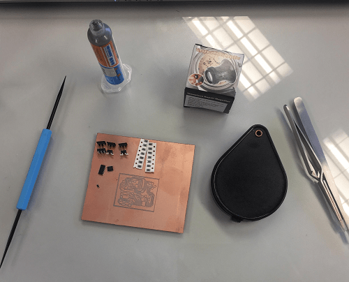
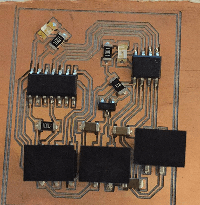
After about 25 minutes I was done(getting better at soldering).
I connected my board to my laptop using my FabISP and an FTDI cable.
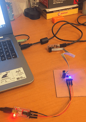
Next, I started my Arduino IDE and selected the right options in the tools area. After, I opened the blink from the examples folder, added some lines of code to make the DC Motor run in one direction for 1 second and then change direction for another second(with the blink following the pattern). It burnt the bootloader on the first try and right after my code updated succesfully.
The next day I went to the lab and connected my board.
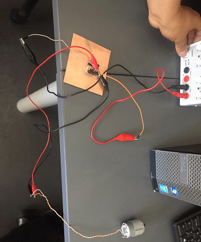
And turned the power on, giving it 12 volts.
Download the original files from the links below:
DC Motor Schematic: Eagle (.sch file)
DC Motor Board: Eagle (.brd file)
DC Motor G-Codes: FabModules (.nc file)
DC Motor Source Code: Arduino (.ino file)