Embedded programming
Table of contents
- Microprocessor
- Tools needed for Windows OS
- Initial test code
- Hello Echo example code
- Using Arduino IDE
- Downloads
Microprocessor
The microprocessor chosen for this assignment, the ATtiny 44, was used in the electronics design assignment. This processor comes in a 14 pin SOIC footprint and has the following specs provided by the data sheet:
| Bus width | 8 bit |
| Flash Memory | 4K |
| SRAM | 256 bytes |
| Speed | 20MHz |
| Peripherals | multichannel 10 bit ADC, 2 x PWM channels, 1 x 8 bit and 1 x 16 bit timer/counter |
| Operating voltage | 1.8-5.5V |
The data sheet for the Attiny44 shows that it is part of a family of processors which range from ATtiny24, ATtiny44 and Attiny84. The larger number indicates the amount of flash the chip has, 2K, 4k or 8K respectively and the amount of EEPROM memory: 126.256 or 512 bytes. The data sheet specifies the operating voltage and at what speed the main clock can run when operating at the various supply voltages.
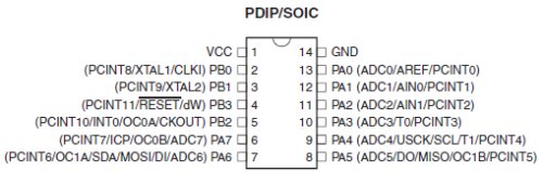
For this assignment pins PA0 snd PA1 are used provide the serial interface to an external computer, with PA0 transmitting data and PA1 receiving data.
Pins PA4,PA5 and PA6 provide the SPI signals, SCK,MISO and MOSI which are used to program the chip.
Pin PA7 will drive an LED while pin PB2 is connected to a push button.
Tools needed for Windows OS
I followed the tutorial for Using the GNU AVR toolchain on Windows 10. To restate, the instructions are:
- Install Git
- Install Atmel GNU toolchain for Windows
- Install GNU Make
- Install avrdude
To check that these have installed properly, in the GitBASH terminal type:
make -v which will return the Make version number.
To check that avr-gcc has installed type
avr-gcc --version which will return the avr-gcc version information.
These tools installed properly in my Windows 7 computer.
Initial test code
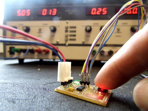
To help test the electronics of my HelloworldNC board I wrote a simple piece of C code that would read in the value of the pushbutton on pin 2 of PORT B and light an LED on PORT A, pin 7.
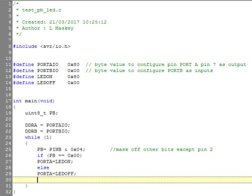
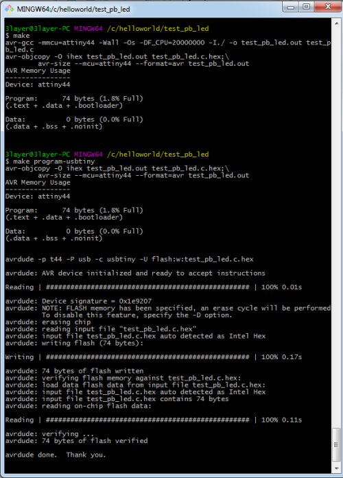
This source code, called test_pb_led.c was created in a text editor and saved to its own folder. A make file was created that contained the instructions to compile the source code to a downloadable hex format and also to program the ATtiny44 using avrdude and the FabTinyIsp programmer. The make file was saved in the same folder. Using GitBASH as the terminal application the working directory was changed to the folder containing the sourcecode and the make file.
Within GitBASH terminal the make command was entered. After the code compiled the HelloWorldNC board was connected to the FabTinyISP programmer. For this test the board was powered from a seperate 5V supply. With everything connected together and the programmer plugged into the computer the command make program-usbtiny was entered in the terminal window and the ATtiny44 flash was programed.
Hello Echo example code
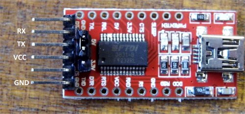
For the FTDI interface I bought a cheap FTDI232R development board and made up a cable that connects the RX,TX,VCC and GND pins to the corresponding pins on my HelloworldNC board.
Before programming the ATtiny44 processor for the Hello Echo example it is necessary to configure it to use the external 20MHz resonator as its system clock. To do this fuses have to be configured on the processor. The command below is taken from the makefile.

However within GitBASH the ATtiny44 fuses are configured by entering the command: make program-usbtiny-fuses
I compiled the example hello.ftdi.44.echo.c obtained from the embedded programming link and programmed the HelloworldNC board. I connected this board to the FTDI232R board and plugged this into a USB port on my laptop. Windows recognised the FTDI board as COM26.
Using Termite as my coms application I set it up to communicate with COM26 with the following settings:
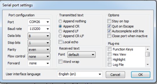
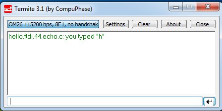
I typed a character in the Termite input text box and pressed the return key and got the following information back.
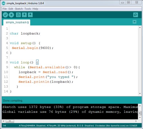
Using Arduino IDE
I decided to write the a similar program using the Arduino IDE. I have described how to use the ATtiny44 within the Arduino programming environment in the Output Devices assignment so won't repeat it here.
The Arduino IDE makes it easy to add serial communication function to the ATtiny44. A screen shot of the code shows how the serial port is initialised and then the code waits in a loop for any characters sent over the serial port by using the Serial.available() and Serial.read() functions and then replies using the Serial.print() and Serial.println() functions. Once the code compiled it was uploaded using the USBtinyisp programmer. Termite application was run as before and worked exactly the same although from the compile message in the Arduino IDE it was noticable that the code now used more of the processor memory.