3 Computer Controlled Cutting
Table of contents
- Introduction
- Laser Cutter
- Solar Kiln
- Laser cutter kerf test
- Librecad
- Importing the design into Inkscape
- Laser cutting the design
- Conclusion
- Vinyl Cutter
Introduction
There are a number of machines that facilitate computer controlled cutting of different materials. The main ones are listed below along with the usable materials.
- Laser cutter : wood, acrylic, abs, cardboard, various fabrics; for example leather, canvas.
- Vinyl cutter : various adhesive and heat transferable vinyls, vinyls for paint and sandblasting stencils, light cardboard/paper.
- Large CNC milling machine : typically used to cut/mill wood and some non-ferous metals.
- Precision milling machine : used to mill copper from pcbs, modelling wax or modelling foam.
Following on from last weeks assignment this week's task involved using the laser and vinyl cutter to make something
Laser Cutter
Solar kiln
For the computer controlled cutting assignment I decided to make a model - 1/6th scale- of a project I hope to complete for the 'Make Something Big' assignment. The model will be of a solar kiln and the point of this assignment is to see if a press fit construction kit of the model can be made.
Laser cutter kerf test
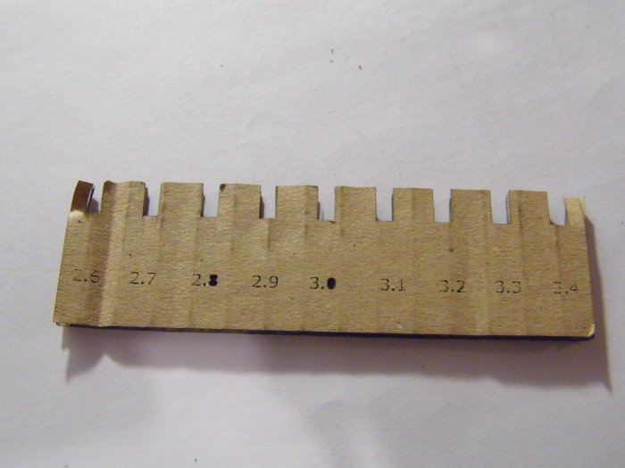
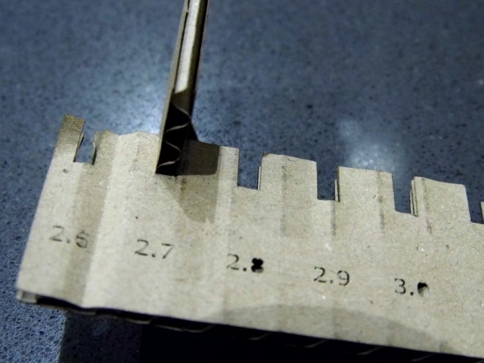
The laser cutter used was an Epilog Mini 24 with a 40 watt tube. Along with my fellow student, Nim, we had two types of materials to cut: 3mm plywood for Nim's assignment and nominally 3mm cardboard which would be used for my model. In both cases the materials had to be cut to produce joints that would press fit together. For this to happen means accurately specifying the joints in the CAD and accurately cutting the design out. With this latter requirement the cutout waste or kerf produced by the laser cutter needs to be known and fed back into the CAD to allow accurate joints to be drawn and then manufactured. To do this a series of joints are cutout on a test sample of material, therby allowing the kerf to be measured and joint widths and heights assessed.
Nim generated an Inkscape file combslottest3mm.pdf which would be used to laser cut the test material and check for slot width and kerf. The first image below shows the cutout template while the second image indicates that for the 3mm cardboard a 2.7mm slot produced the best fit. A 30mm square was also cut out and this was measured to see how the dimensions had reduced due to kerf.
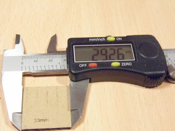
With the kerf test using the 30mm square the cut piece was 0.74mm short, ie. instead of 30m wide it was 29.26mm. This gives a kerf of 0.74mm/2 equals 0.37mm.
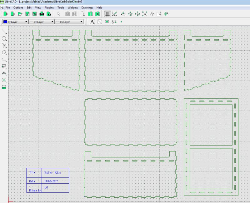
LibreCAD
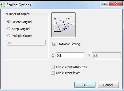
I designed the model using LibreCad. This is free 2D design software. We had been told to use CAD software that was parametric which allows a design object to be drawn containing geometries that are related to each other via rules created by the designer or CAD tool. This means the drawing can be easily modified to meet new design scenarios such as a change in the thickness of build material or resizing part of the design which automatically causes any related parts to resize also. When later I had a problem fitting the design to a size suitable for the laser cutter I was able to use the scale parameter to modify the design.
The LibreCAD solar kiln design is shown below while the full design can be downloaded from solarkiln.dxf
The Epilog Mini24 has a cutout bed of 600x300mm so it became obvious that I couldn't cut my design in one go. I decided to divide the design into two drawings but even then it was going to be a problem fitting it all on to the laser bed so I decided to rescale the design so that the solar kiln could be cut on two seperate sheets. It is easy to rescale things in LibreCAD. In the drawing area select all the objects then from the menu select
Tools->Modify->Scale
Enter in the scaling factor : the X and Y axes can be scaled seperately
The scale method demonstrated here presents a way the CAD tool can be used to resize a drawing with user entered parameters such as X and Y scale. With this, the original design can be modified so that all parts of it are adjusted by the same numerical value.
The design was scaled down to 80 percent and divided into two drawings. The problem with scaling was the slots which had been designed for 3mm material were now reduced in size to 2.4mm. Within LibreCAD I had created a 'slot' block, a cutout 3mm x 15mm, which meant it could be edited seperately from the design allowing me to change the slot to accomodate 3mm material.
LibreCAD Blocks
Blocks in Librecad are independent design entities that are used to create a parts library that can be reused and parametrised so that if the original block is modified any designs incorporating the block will feature the modification. The link here gives a better understanding of how to use blocks in LibreCad
I created a number of blocks in Librecad that would allow the design to be changed by modifying the block rather than having to modify parts of the main Solar Kiln drawing. The screen shots below shows the blocks used in the Solar kiln design. Blocks are placed on the main design by highlighting the block in the block list and then clicking on the insert button to place the block in the design, using the mouse to place the block where it is needed. In this example the fingers that would mate with the slots were added to the design. If the fingers need modified, for example to account for kerf, then the finger block can be changed and any parts of the design featuring this block will be updated with the changes.
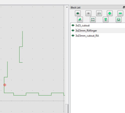
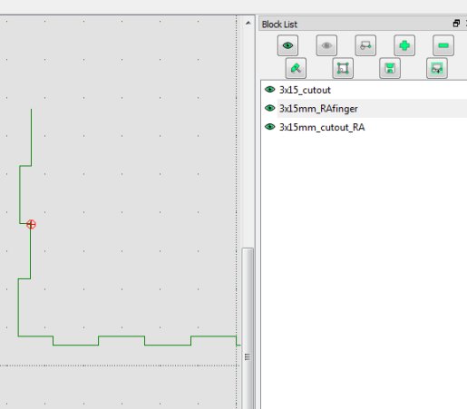
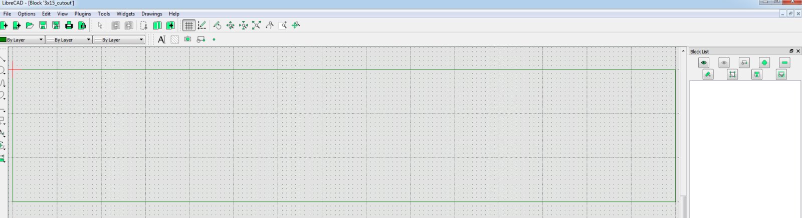
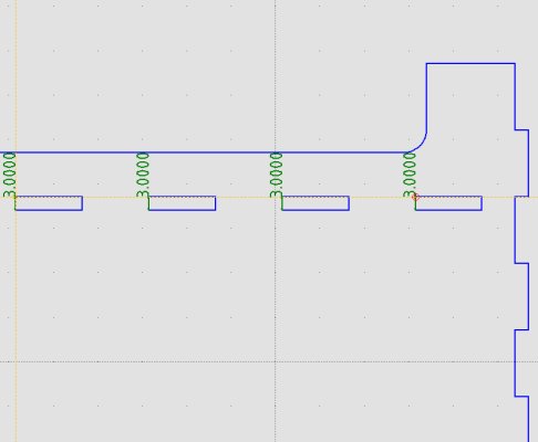
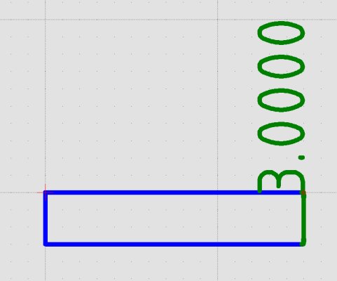
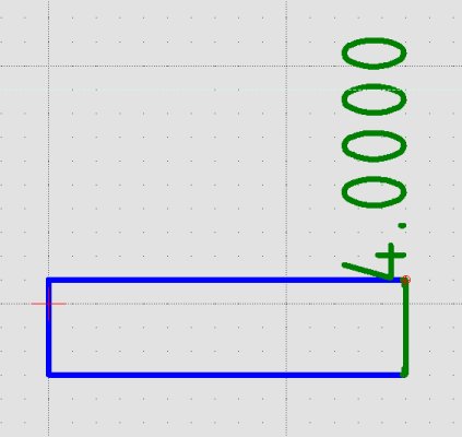
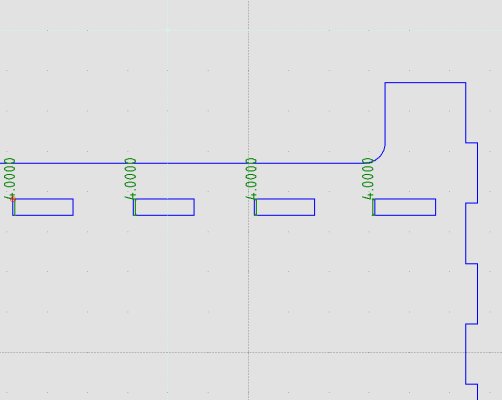
As an example of modifying a block the 3x15_cutout can be edited in Librecad by selecting it from the block list and selecting the edit tool which will open a new Librecad window for editing. The screenshot below shows the slot in edit mode where its length and height can be modified - click on the image to view it in higher resolution. Once modified the slot with the new dimensions will be updated in the main drawing. A Librecad drawing can be composed of many such objects which can be edited separately from the main drawing allowing further parameterisation of the design if necessary.
I decided not to change the slot parameters because I believed the 2.4mm slot size along with kerf would still allow a press fit. However, to show how to the parametric changes on the slot height are reflected in the main solar kiln drawing I have described an example here where I changed the slot height from 3mm to 4mm to accommodate a thicker material. Any changes I made to the slot height should then be shown in the main drawing. The images below show this process where the original slot height dimension is shown in the main drawing and in the slot editing window. Next the slot height is adjusted to 4mm and the final image shows this in the main drawing across all the slots. Note I have changed the background colour and outline colours to make things easier to see and I used the original unscaled Solar Kin drawing not the 80% scale that was used to cut out the parts on the Epilog laser.
The scaled LibraCad files for the Solar Kiln can be downloaded from the links below
Importing the design into Inkscape
The LibreCAD drawings were imported as dxfs into Inkscape but a problem immediately became apparent where some of the slot objects that had been rotated through 90 degress in the CAD drawing were not rotated in Inkscape.
This is an Inkscape problem as the dxf's were read properly in QCAD. As a way round this I opened the LibreCAD files and created 'slot' objects that were rotated 90 degrees and replaced the original horizontal slots that had been rotated through 90 degress in the drawing with these new vertical slot objects.
The new drawings were saved and imported into Inkscape. In Inkscape the stroke fill was changed to 0.01mm to allow laser cutting and the Inkscape files were saved as PDFs.
- solarkiln_80pcnt_part1.svg
- solarkiln_80pcnt_part2.svg
- solarkiln_80pcnt_part1.pdf
- solarkiln_80pcnt_part1.pdf
Laser cutting the design
The laser cutter was setup with the following parameters
- Power :95%
- Speed :20mm/s
- Frequency: 500Hz
- Vector only
- Auto focus on
Just before the parts were to be cut it was discovered there was not enough of the 3mm carboard which had been used to calculate kerf and slot width. A similar type of cardboard was used but it turned out this was 4mm thick and at this stage it was too late to go back into Librecad and make the chamges so I decide to go ahead and cut the design with the thicker cardboard
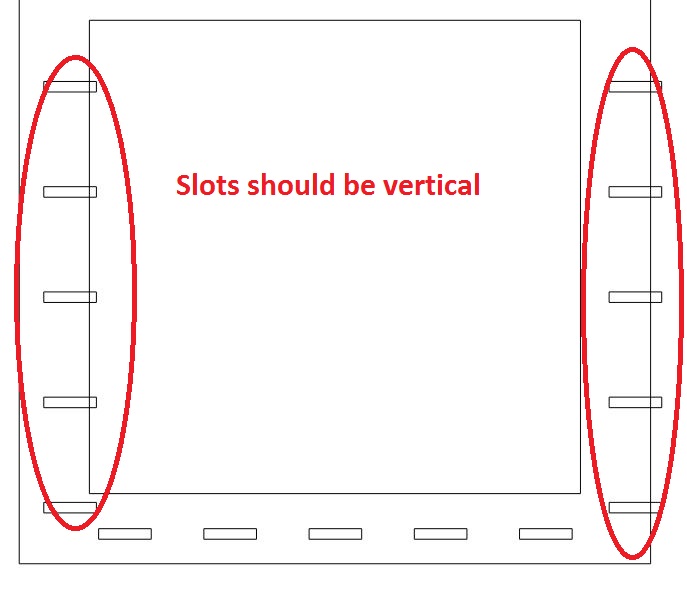
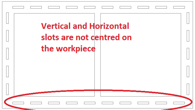
Also during cutting I noticed that Inkscape had insertd a small offset in the positions of the vertical and horizontal slots so that they weren't positioned properly
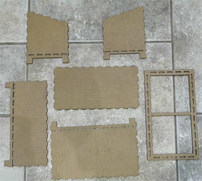
The cutout pieces of the flat pack model are shown below. IKEA you have nothing to fear!
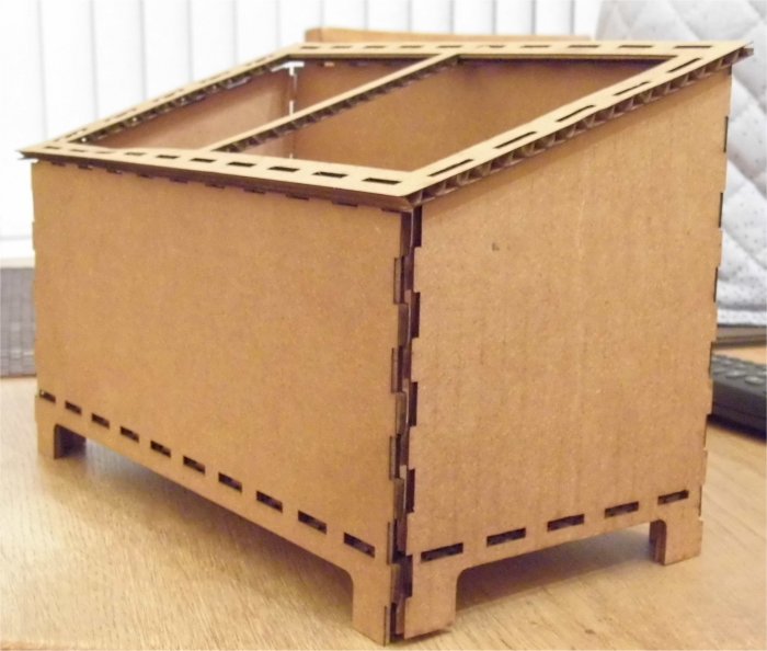
The final assembled model is shown below. Like its creator the model is just about holding together.
Conclusion
It's literally back to the drawing board for this with a number of lessons learned.
- Design has to be easier parametrised in LibreCAD or other software to allow different materials and scale to be selected.
- Problem of exporting to Inlkscape needs sorted.
- Actual design needs looked at - are slots/cutouts in the right places.
- Angle of solar collecting is not large enough.
- Make sure there is enough material to cut the design.
Presently it's a case of don't try this at home until the issues listed above are sorted.
Vinyl Cutter
The second part of this project was to use a vinly cutter to cut something. The Nerve Centre Fab Lab has a Roland GS-24 vinyl cutter and I had a chance to watch my collegue Nim cut a couple of designs on the cutter using Inkscape generated art work and Roland Cut Studio to control the GS-24. I didn't have a chance to use the GS-24 but I have a Silhouette Cameo 2 cutter and I used this to make a laptop sticker.
Generating the artwork
I opened a new document in Inkscape and imported a black and white jpeg of the Fab Lab logo. With the imported image selected the Trace Bitmap function was chosen from the menu. The edge detection algorithm was used with the threshold set to 1. I found this to give the best results- depending on the image other algorithms and settings may need to be tried. The screen shot below shows the imported image on the left and the traced bitmp on the right.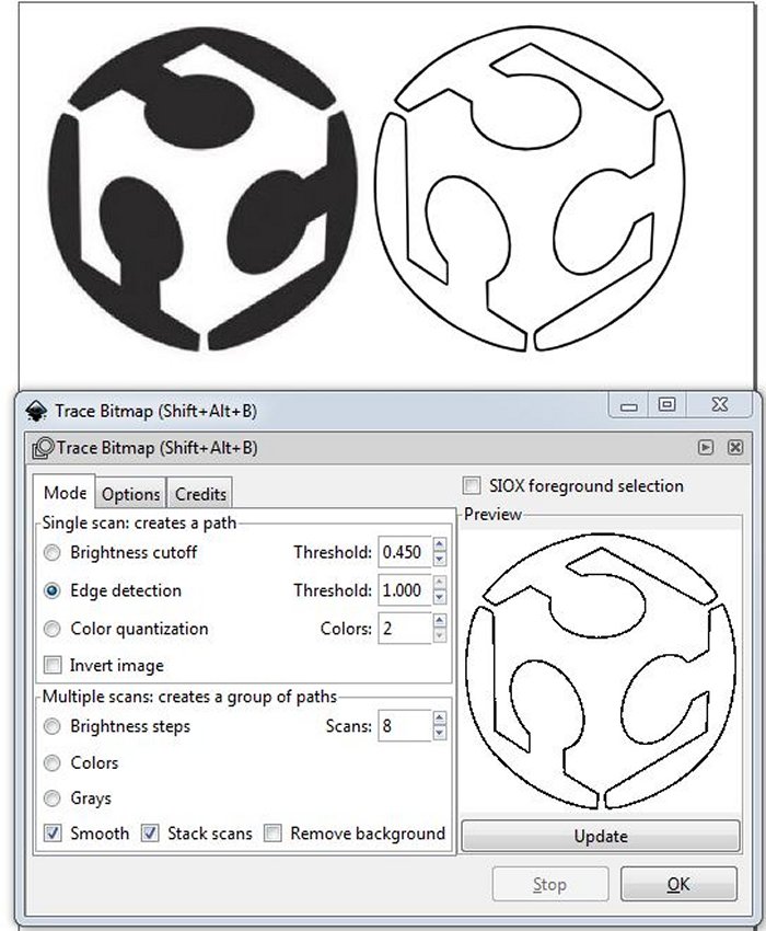
The imported jpeg was deleted from the Inkscape document leaving only the traced bitmap. The Inkscape document was then saved as an svg file and also as a png
Silhouette Studio Basic Edition is a free version of software that Silhouette provide to control their vinyl cutters. I opened Silhouette Studio and in the file menu selected to open the Inkscape generated png of the Fab Lab logo.
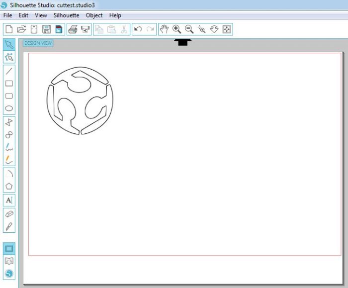
With the image selected, in the menu go to Object->Trace which loads a toolbar allowing the image to be traced and its various edges detected. This is duplicating what Inkscape did so in practice the original logo could be loaded into Silhouette Studio and the image processed there but having the processed image in Inkscape allows other cutters/machines to be used.
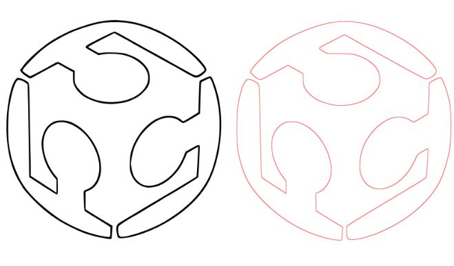
 In the trace toolbar the images outeredge was traced producing a vinyl cutout vector shown below on the right -original image on the left.
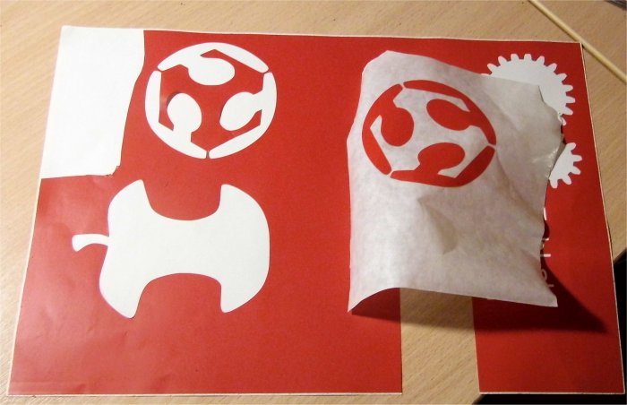
The original bitmap was deleted and vinly media loaded into the Cameo 2. From the Silhouette menu the cut settings were set for the media and the file was sent to the vinly cutter. The results are shown below.

Using Roland GX-24 vinyl cutter
I was able to get a Roland GX-24 vinly cutter and produced a tutorial showing how to use it, which includes generating original artwork using Roland CutStudio. Visit Roland GX-24 tutorial