2 Computer Aided Design
The task for this assignment was to use computer aided design (CAD) tools to draw in 2D and 3D, a representation of the students's final project. During the class lecture on this topic various CAD tools were listed with a distinction made between raster and vector drawing tools and between open source/free tools and commercially licensed tools. Through the Fab Academy the students were able to get a temporary license (1year) for Solidworks and Autodesk. At the class lecture it was emphasized we try as many of the CAD tools as possible in order to find tools that we could work with and that were best suited to the design.
In reality I was unable to test drive a lot of the CAD tools mentioned. I spent most of this week's time trying to figure out the dimesnsions and geometry of my final project design,- Stirling Engine Stove Fan- so that I could draw it. In the end I opted to use an exsiting engine design as the basis for my CAD drawing project.
However, from talking to other students and my instructor useful CAD tools that meet the requirements of ease of use and price are listed as
- Rhino
- Inkscape
- CorelDRAW
- FreeCAD
- TinkerCAD
- Solidworks
Over the course of the Fab Academy I intend to gain some experience of the above tools and will be able to update this page with the results
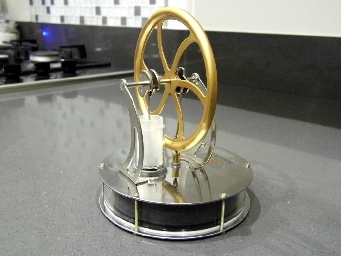
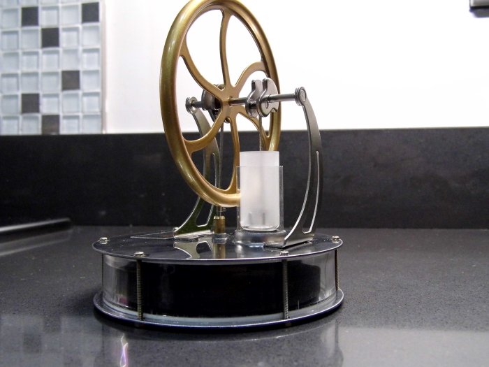
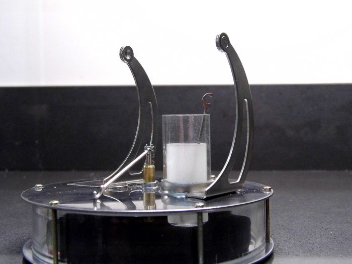
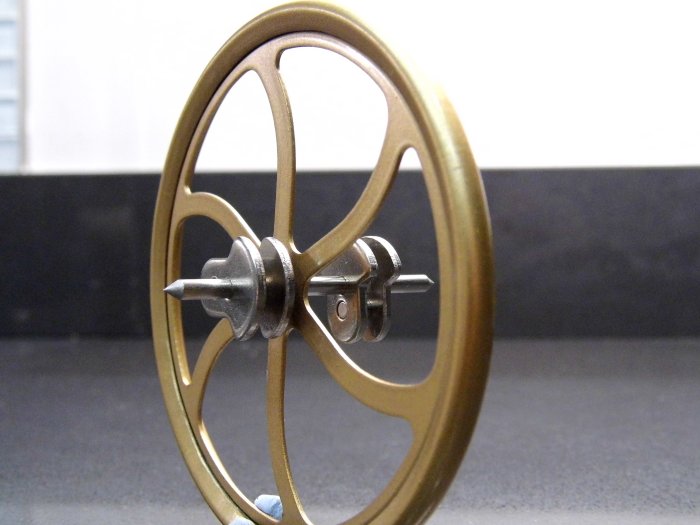
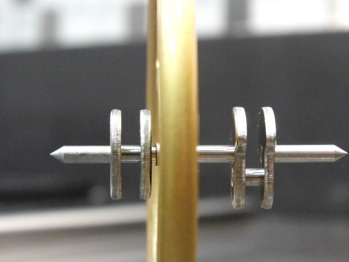
Existing Engine
Some images of a Stirling Engine used for educational purposes are shown below. Scroll through them to see the various engine parts such as the flywheel, crankshaft and pistons.
Inkscape
First thing I did in Inskscape was to go to File->Document Properties and set the page size to A3, Orientation to Landscape and the Default Units to mm.
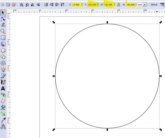
The screenshot below shows the initial drawing of the engine flywheel: it's a circle with diameter 100mm. To do this with Inkscape draw the circle and in the W
and H fields (highlighted) change the dimensions to the value needed - in this case 100. The other parameter fields higlighted X
and Y are the X and Y co-ordinates of the drawn object. These coordinates are useful when an object needs moved to
an exact position.
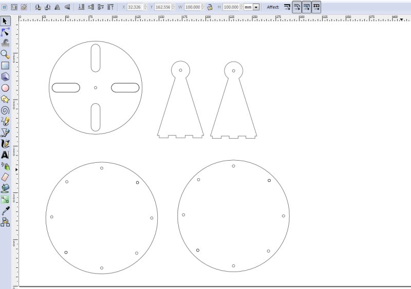
After drawing the flywheel circle I added a few slots and a centre hole for the crankshaft. The slots were drawn by intially drawing one slot and then cloning it using the ALT D short cut. This means that if the original parent is changed then all cloned offspring will change. This is a useful feature and allows dimensions to be easily changed if required. The Align and Distribute tool was used to place the slots equally around the flywheel circle.
I added some more engine parts to the design
- crankshaft support brackets
- top and bottom displacement cylinder plates
Further engine parts will be added to this drawing before attempting to cut them out using the laser cutter.
Solid Works
After I changed my project from a stove fan to solar kiln I did the solar kiln drawings in Solid works.
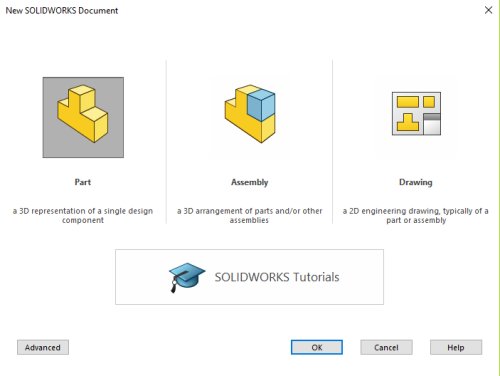
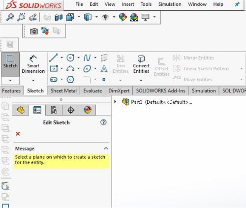
To create the drawings and 3D files for the Solar Kiln using Solid works the first thing is to start the software and create a new part.
A sketch was created for the relevant part using the sketch drawing tools: lines, rectangles, circles etc. When creating a sketch the user will be prompted for the drawing plane. I used the plane best suited for the part, for example the front plane for the front of the Solar Kiln and so on.
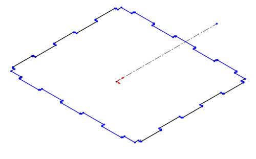
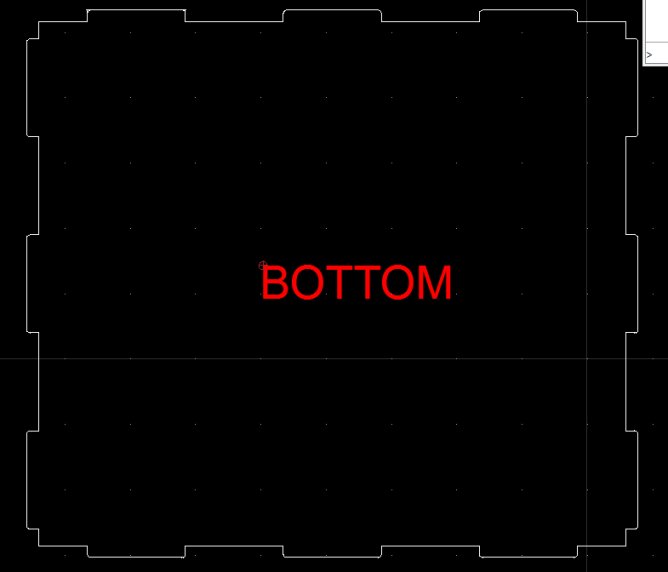
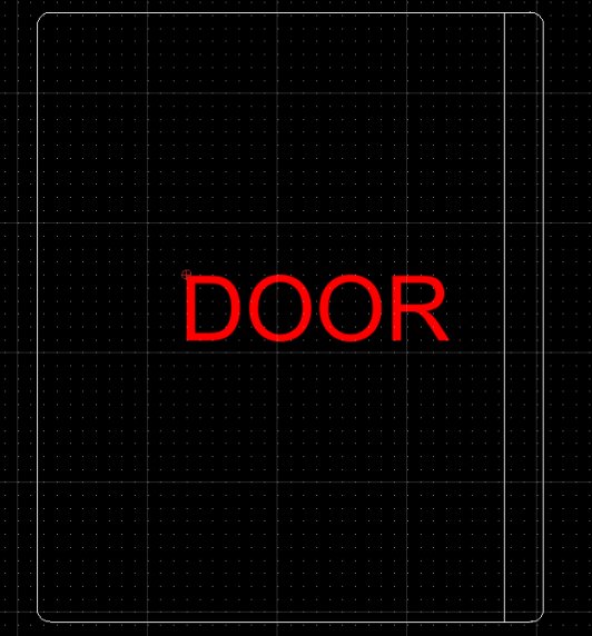
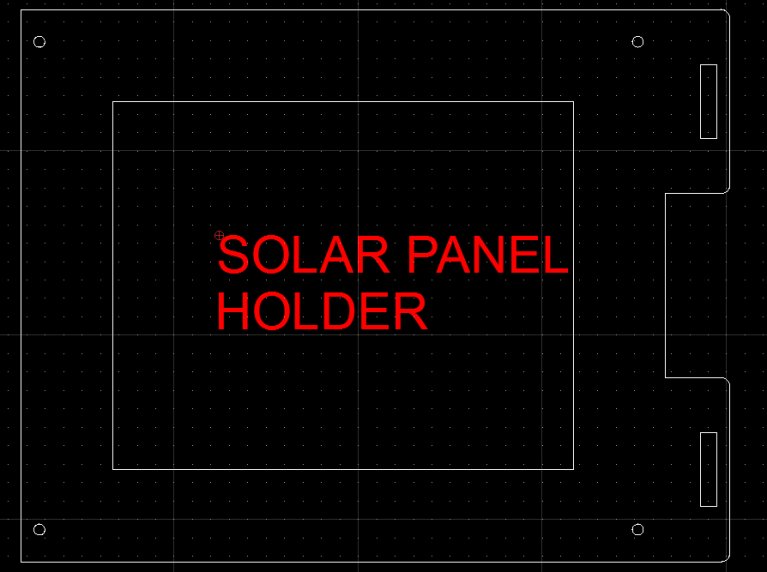
I mainly used the line tools to draw the shape of the various Solar Kiln parts. The screen shot below shows the Solar Kiln base.
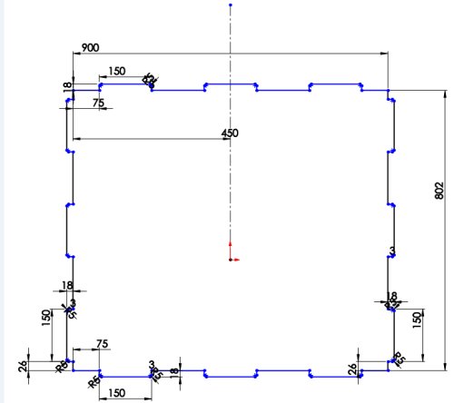
Dimensions are added to the drawing by using the Solidworks smart dimension tool. Selecting this tool and then selecting the drawing entity allows the entity dimensions to be modified. I followed this process for all the parts of the Solar Kiln, creating a part, then a sketch of the part and dimensioning the part to the correct size.
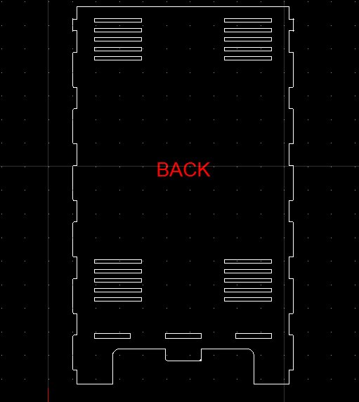
As each part was completed it was also saved as a dxf which would then be used by the Shopbot to cut out the part. The final design for this can be found on my final project page along with the design files which are linked below.
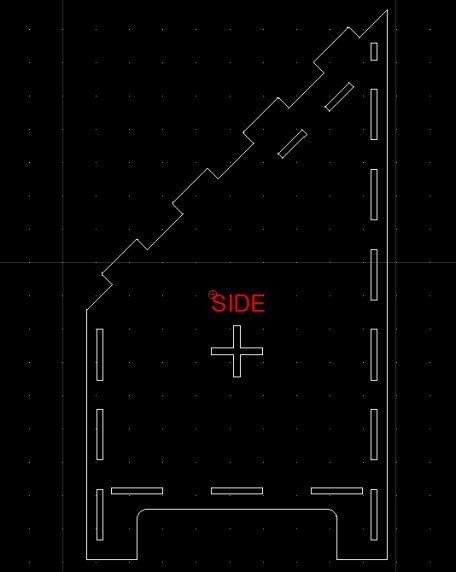
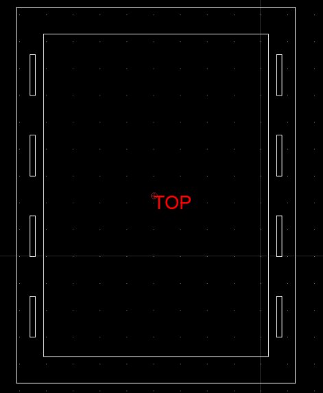
The screen shots below also show the various drawings of the Solar Kiln
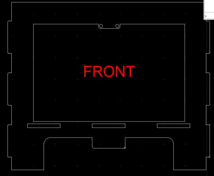
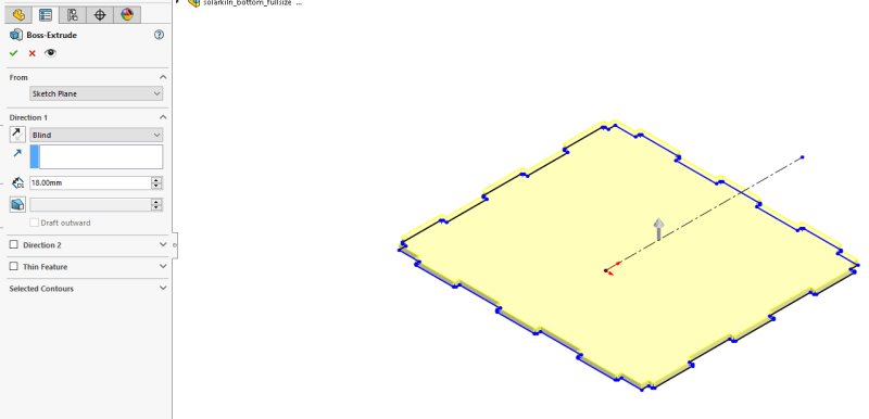
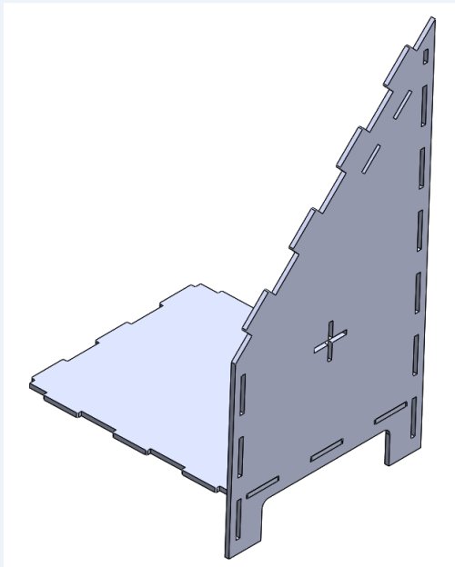
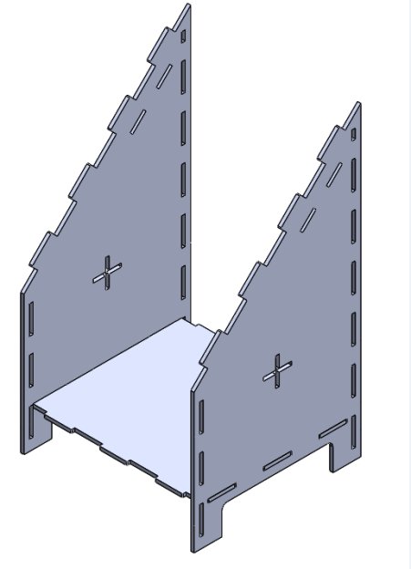
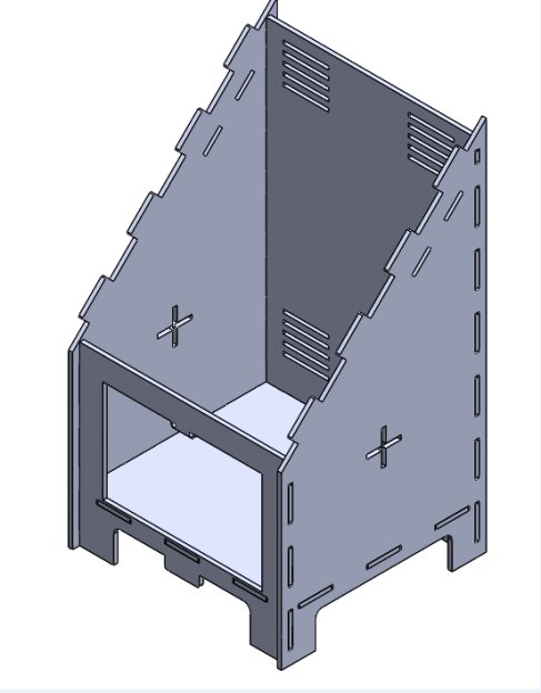
Each part was also extruded to the correct material thickness as this would then be used to make an assembly of all the parts to see if they would fit together.To extrude a sketch, with the sketch selected, click on the Feature menu and select Extrude Boss/Base. The direction and the extrude dimensions can be then set in the property fields of the Extrude Boss/Base Property Manager.
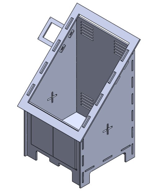
With all the parts extruded a new assembly was made that positioned all the parts correctly. From the toolbar select New->Assembly and select the first part. Then each part of the Solar Kiln was inserted. As it was inserted it was positioned correcting using the mating function to align the parts and the joints.
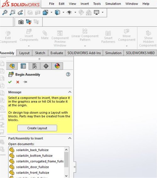
Images of the various parts that made up the Solar Kiln along with the completed assembly are shown here.