PCB + ECAD design
The rescue notification system consists of the help! button with RF transmitter and the hub with RF receiver and WiFi connectivity. Below you will find a description, a list of components and the parts list.
Board 1
This board is an ATmega328 board and had the Networking week board as a reference. This card sends data with the 433 MHz transmitter when the button is pressed.
CONTROLLER
The controller on the board is an
ATmega328P, this board is an Arduino IDE compatible base board. The ATmega328 is the same controller as on an Arduino Uno board.
PROGRAMMING interface
On the board are the necessary pins for an ISP interface.
The pinout is like on an Arduino Uno.
RF MODULE
A 433 MHz transmitter is installed on the board. The boards 1 and 2 communicate only in one direction Tx → Rx via the RF link.
POWER SUPPLY
The board is powered by two CR2032 (3 V each) button cell batteries, making the board portable. A linear voltage regulator is mounted on the board and generates a stable 5 V voltage supply.The board has an operation voltage up to 5.5V according to the datasheet of the ATmega328, page 258:
- Operating voltage: 2.7V to 5.5V for ATmega328P
- DC current VCC and GND pins: 200 mA
- Maximum current per port = ±30mA
The operation voltage of the 433 MHz transmitter is 3,5 – 12 V DC.
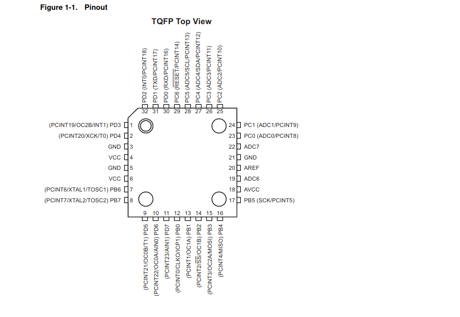 ATmega328 pinout
 ATmega328 dimensions
B1: Designing the board
I want to start the design and noticed that the library for the Atmega328P-AU is missing.
In
snapeda.com I download the symbol and footprint for Eagle and the 3D model.
FEEDBACK
from my instructor: I should reduce the size of the board. For this, only the necessary components have to stay on the board. This way the board needs less power and can last longer with smaller batteries. I should check if sleep functions are necessary in the code.
When designing the board I remove all pins and connectors I don't need and leave only the necessary pins for the connection to a programmer or FTDI board.
Finally, I draw a 19 x 19 mm placeholder for the RF transmitter module, because I have to place the pin head for it and check if there is enough space. I also place the smd pushbutton near the center of the board because the hole lid will be the push button.
I will be able to make further adjustments once I have printed the case.
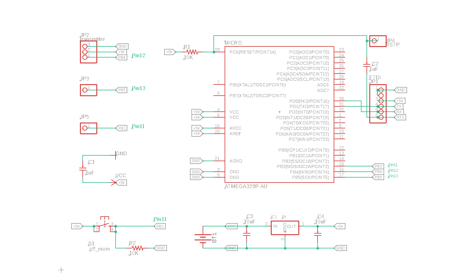 Board 1: Schematic
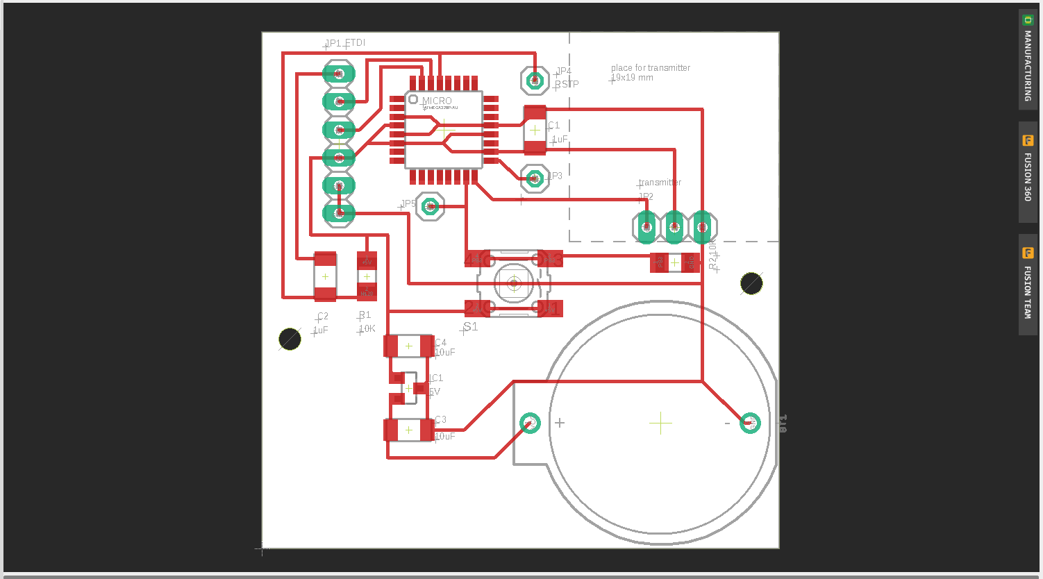 Board 1: Board design
B1: Design Update
After some attempts and reading from tutorials I can't program the board shown above. I use a programmer and the Arduino Uno as ISP and many different settings that I research. But I always get the same error displayed. Even when I replace the microcontroller, if the first one was damaged:
'Yikes! Invalid device signature! Double Check connections…'
I read about this error message and realize that the error message is related to the Fuses issue. I try to solve the problem without success. Due to time constraints, I decide to add a few of the removed components back to the board so that the bootload works as an Arduino Uno. The next reason is that the library for RF communication runs reliably on an Arduino Uno.
After the board is bootloaded, I load the first test code (Blink) and it works! I solder the remaining components like button, voltage regulator as well as battery holder. Unfortunately, the sketch no longer runs and realize that the footprint of the voltage regulator is wrong and remove it. I insert the right footprint into Eagle and correct the design. The board runs fine and can communicate via 433MhZ.
 Board 1: new schematic
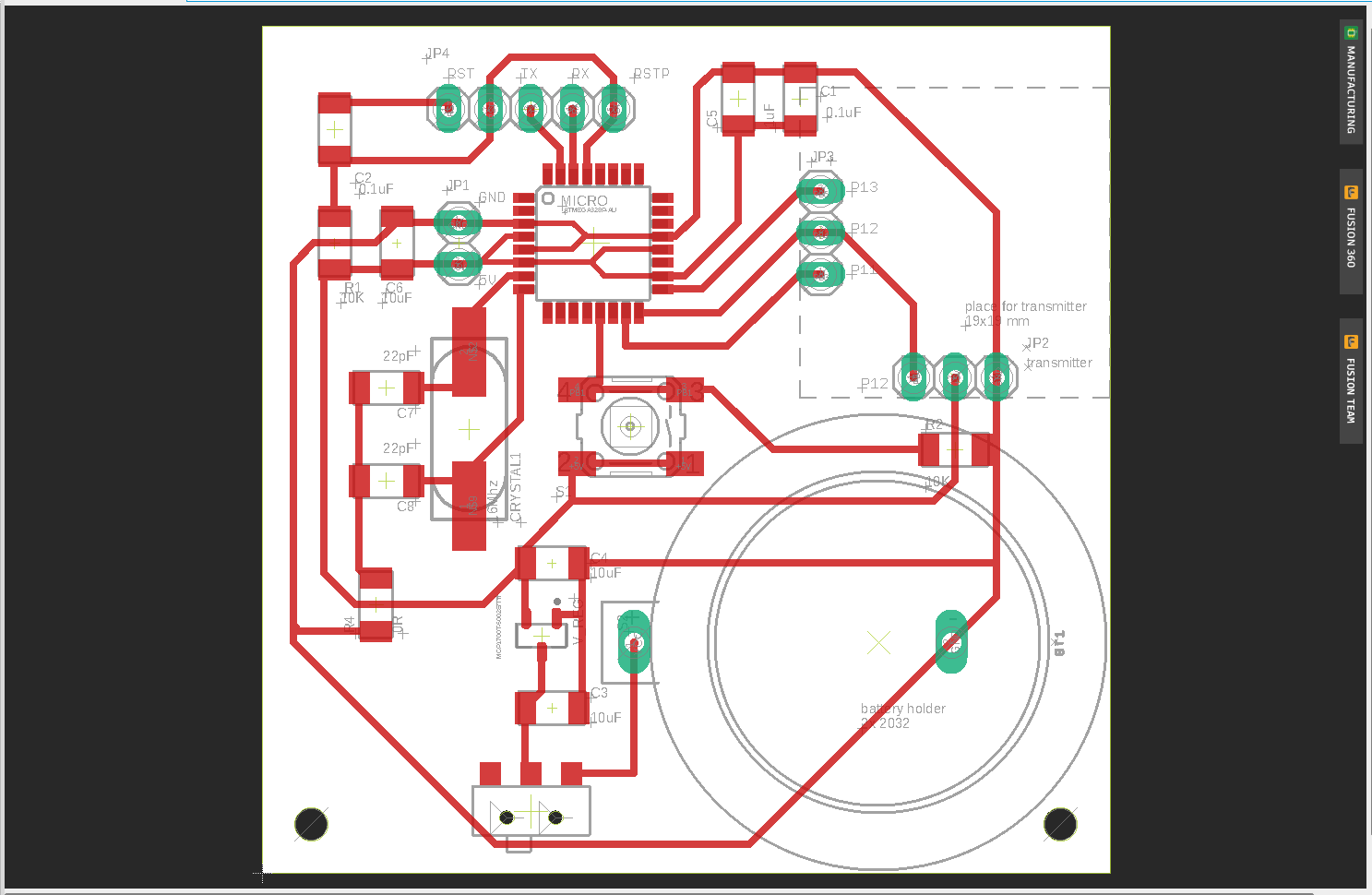 Board 1: new board design
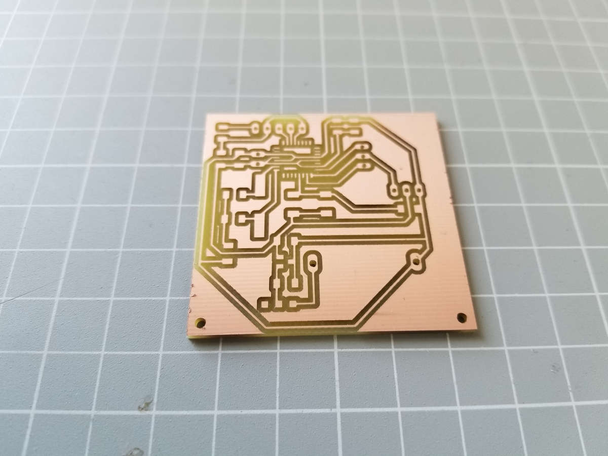 Board 1: milled board
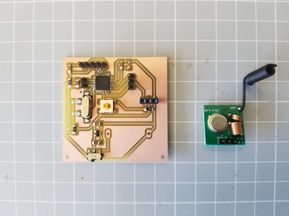 Board 1: with components
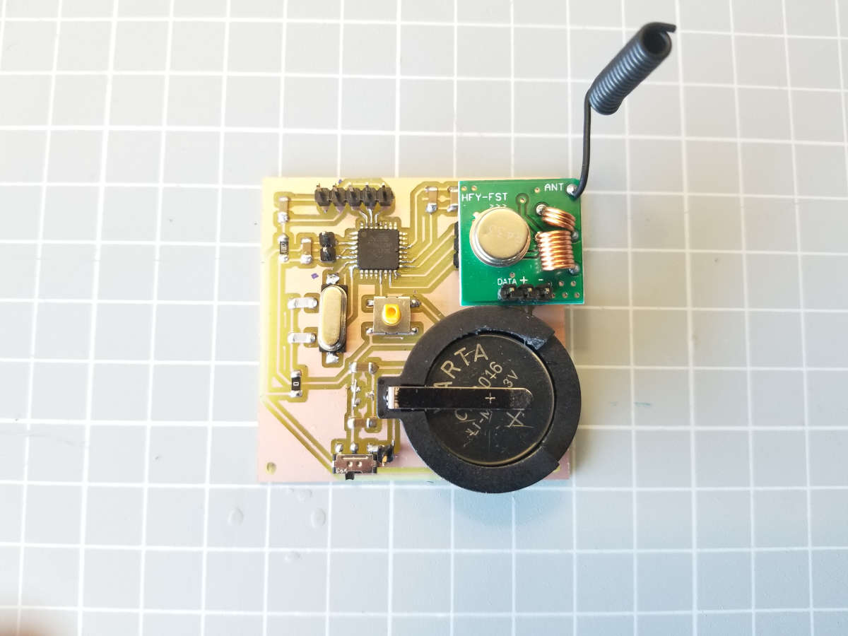 Board 1: finished
B1: COMPONENTS | Electronics
- Radio transmitter 433 MHz
- State button for sending the emergency message
- Capacitors, resistors and pin heads
- Microcontroller ATmega328
- Switch button to turn the device ON/OFF
- Power supply: batteries and battery holder)
- Circuit board
I reduced the size of the board so that the batteries can last long. These components are omitted:
x State button for Reset
x Voltage regulator for 5V
x LEDs: green, red and blue or multicolor LED
x Speaker
B1: VENDORS | COST
Here's the BOM for first board. I ordered the most of the components from Germany. The first board should cost about 8,90€. Add to this the cost of the batteries, the prototyping board and the use of the CNC machine.
Board 2
This is an ESP32 board and Arduino IDE compatible. It receives data via the 433 MHz receiver and automatically sends an email via the WiFi module.
CONTROLLER
The controller on the board is an
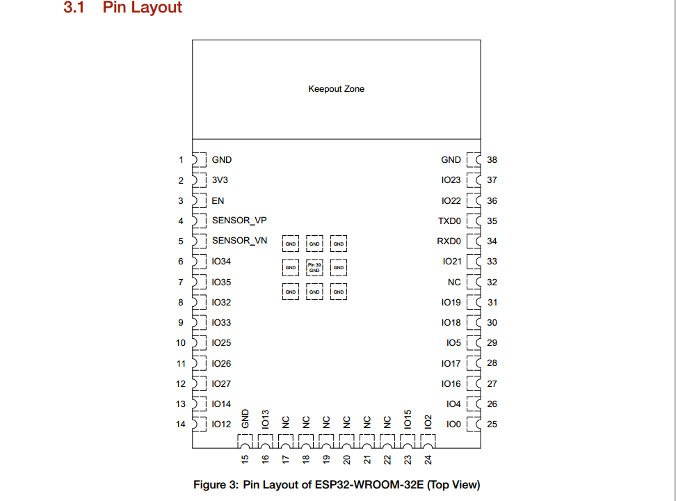
ESP32-Wroom module with WiFi and Bluetooth connectivity.
RF MODULE
A 433 MHz receiver is installed on the board. The boards 1 and 2 communicate only in one direction Tx → Rx via the RF link. This board cannot send data to the board 1.
PROGRAMMING interface
On the board are the necessary pins for an ISP interface:
VSPI: GPIO 23 (MOSI), GPIO 19 (MISO), GPIO 18 (CLK), GPIO 5 (CS)
More about the pinout:ESP32 Pinout Reference
POWER SUPPLY
This board will be permanently on so that it can receive the RF data at any time. The power supply is via a plug-in power supply. The board has an DC barrel jack connector and voltage regulators for 5V and 3,3V. The voltage regulators are necessary because the operating voltage of the RF module is 5V. The ESP32-Wroom operates with 3.0-3.6 V.

B2: Designing the board
Before I start drawing in Eagle, I am looking for some references that have the ESP32-Wroom as a base. I find these reference projects or pages:
- Main Plate (ESP32-WROOM ver. 3) on EasyEDA
- Morp3dbot
- DOIT ESp32 DEVKIT V1 BOARD
Then I download the library (ESP32-WROOM-32D) with the icon and footprint and add the library to Eagle. The next step is to determine which components remain on the board and which do not. I want to have a small basic ESP32 development board without the USB interface and delete the CP2102 chip and the USB connector. I leave the pins for the UART and SPI interface on the board. Finally I add the pins I need, for example for the RF receiver (GPIO 4), the OLED mini display (GPIO22/SCL and GPIO21/SDA) and the LEDs (GPIO 14, 25 and 33).
The operating voltage of the ESP32-Wroom board is 3.3 V. The operating voltage of the RF receiver and the screen is 5V. Therefore a voltage regulator with 5V voltage output is added.
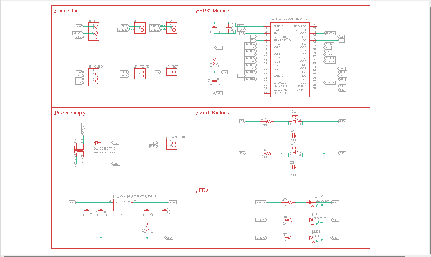
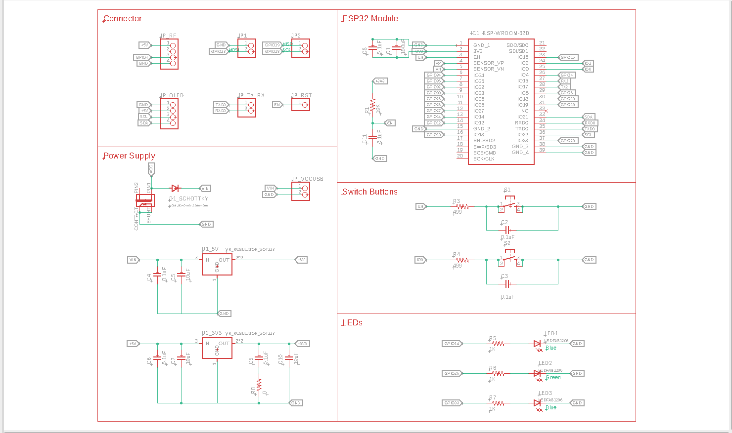 Board 2: Schematic
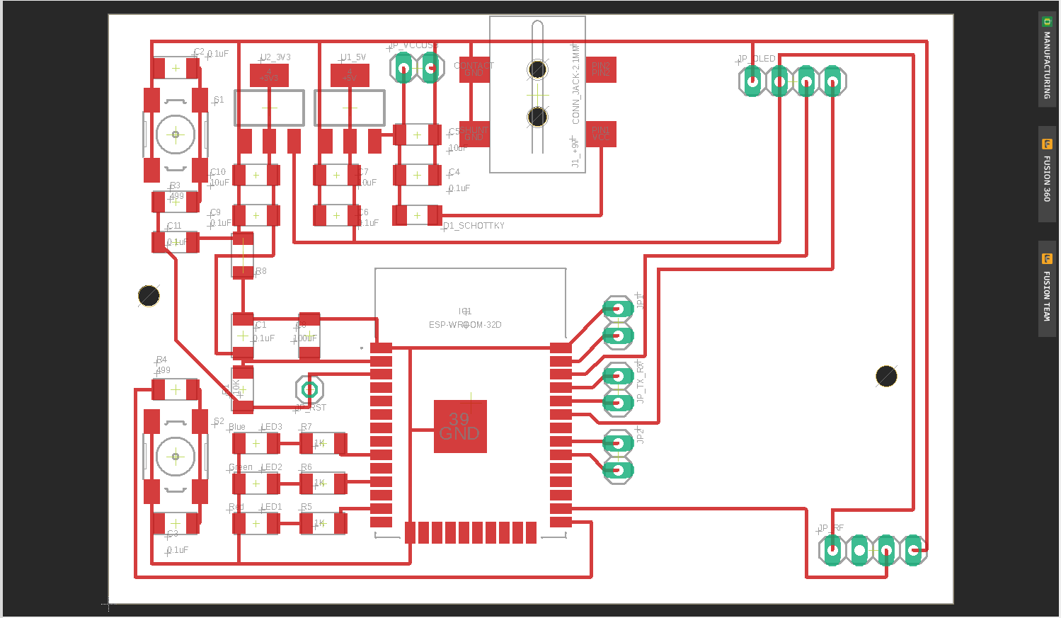 Board 2: Board design
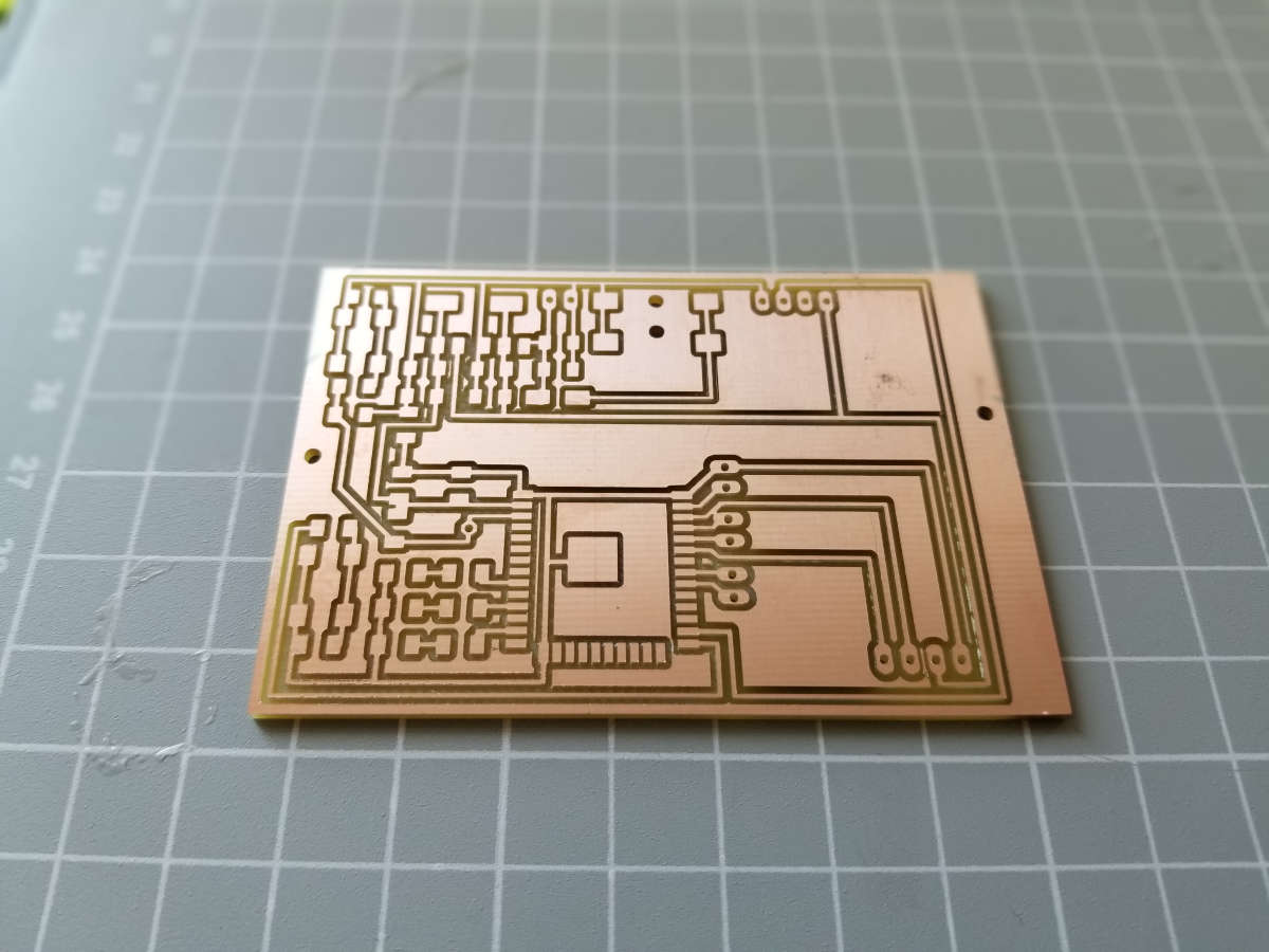 Board 1: milled board
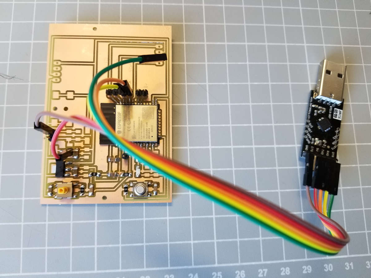 Board 2: with components _ flashing
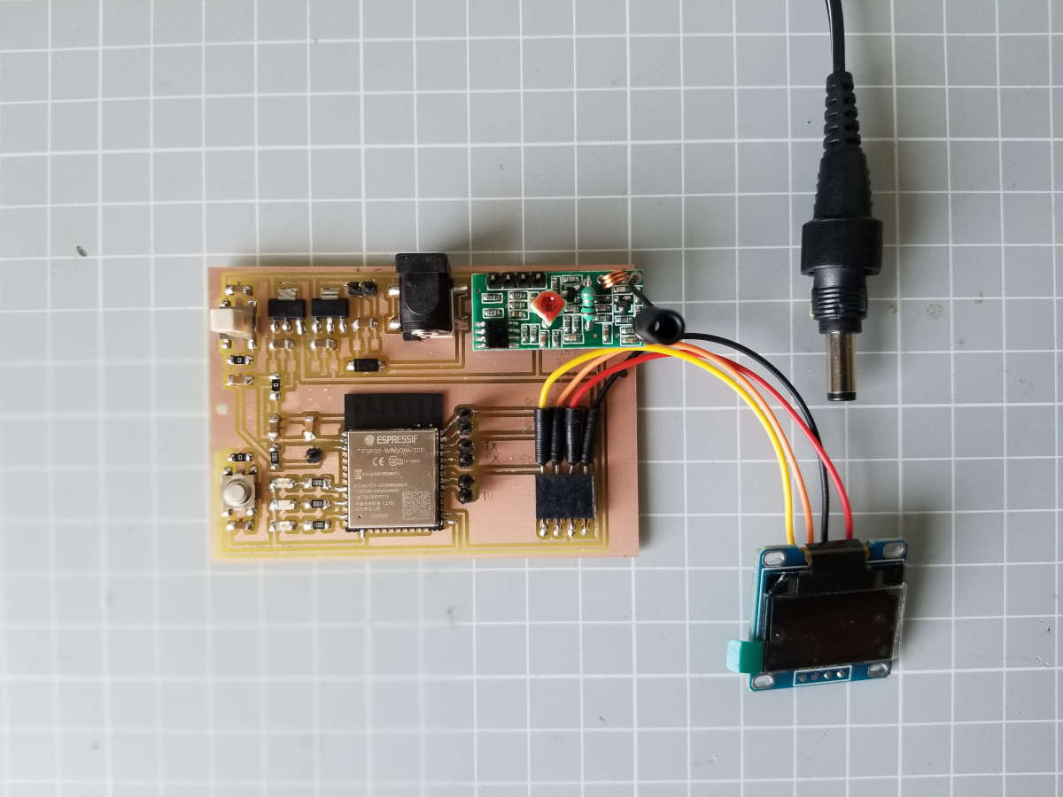 Board 1: finished
B2: Programming
I do some research on how to upload an example code to my ESP32-board and found this tutorial and a video. In the code part of my final project, I describe how to add the ESP32 to the Boards Manager of the Arduino IDE. I have a USB to Serial port converter with a CP2102 chip on it, now I can start wiring it up:
USB port conv. → ESP32
GND → GND
TXD → RXD
RXD → TXD
5V → voltage regulator input or 3V3 → 3V3 on the ESP32
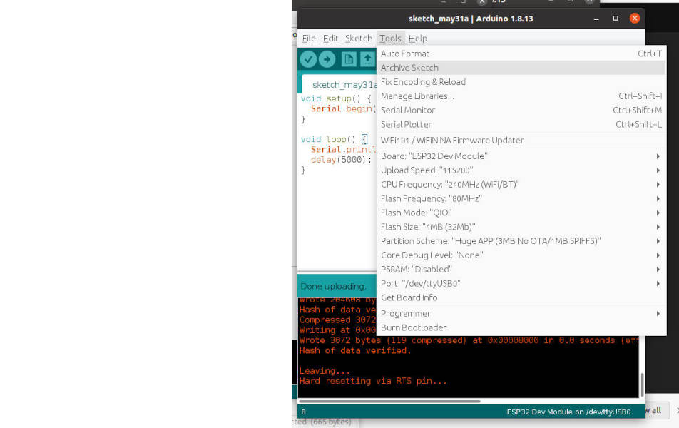
The operation voltage of the ESP32 is 3.3V. I solder the voltage regulator and the capacitors so that I can connect the 5V (USB) to the board. Before I upload the code, I select the right board (screenshot) and press the ‘boot’ and ‘reset’ button at the same time to start the programming mode of the ESP32. Finally I can upload the example code.
 Board 2: programming
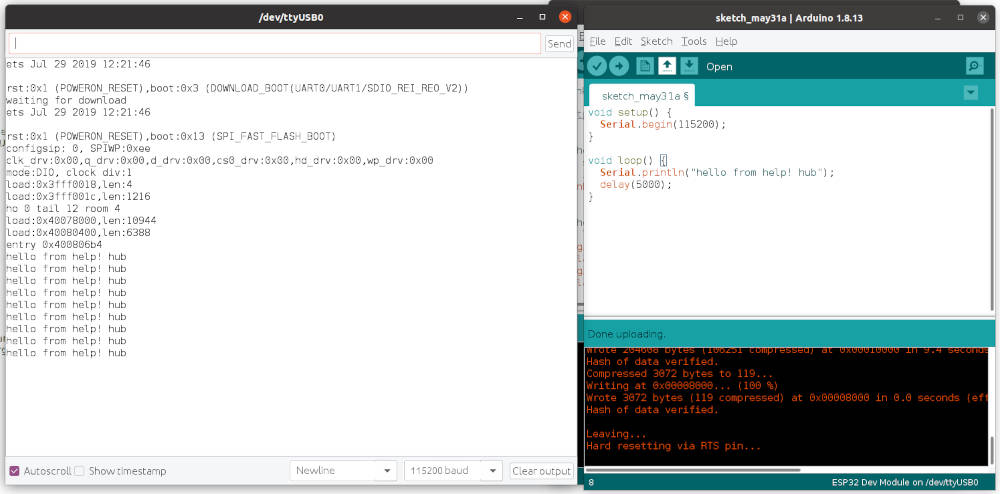 Board 2: programming
B2: Design Update
First I solder the necessary components from this reference to program the ESP32-WROOM. The board will not have a CP2102 chip on it, so the number of components is much lower. Also, I now have a power plug with 5V output and can omit the first voltage regulator. This also makes the board cheaper and possibly smaller.
 Board 2: new schematic
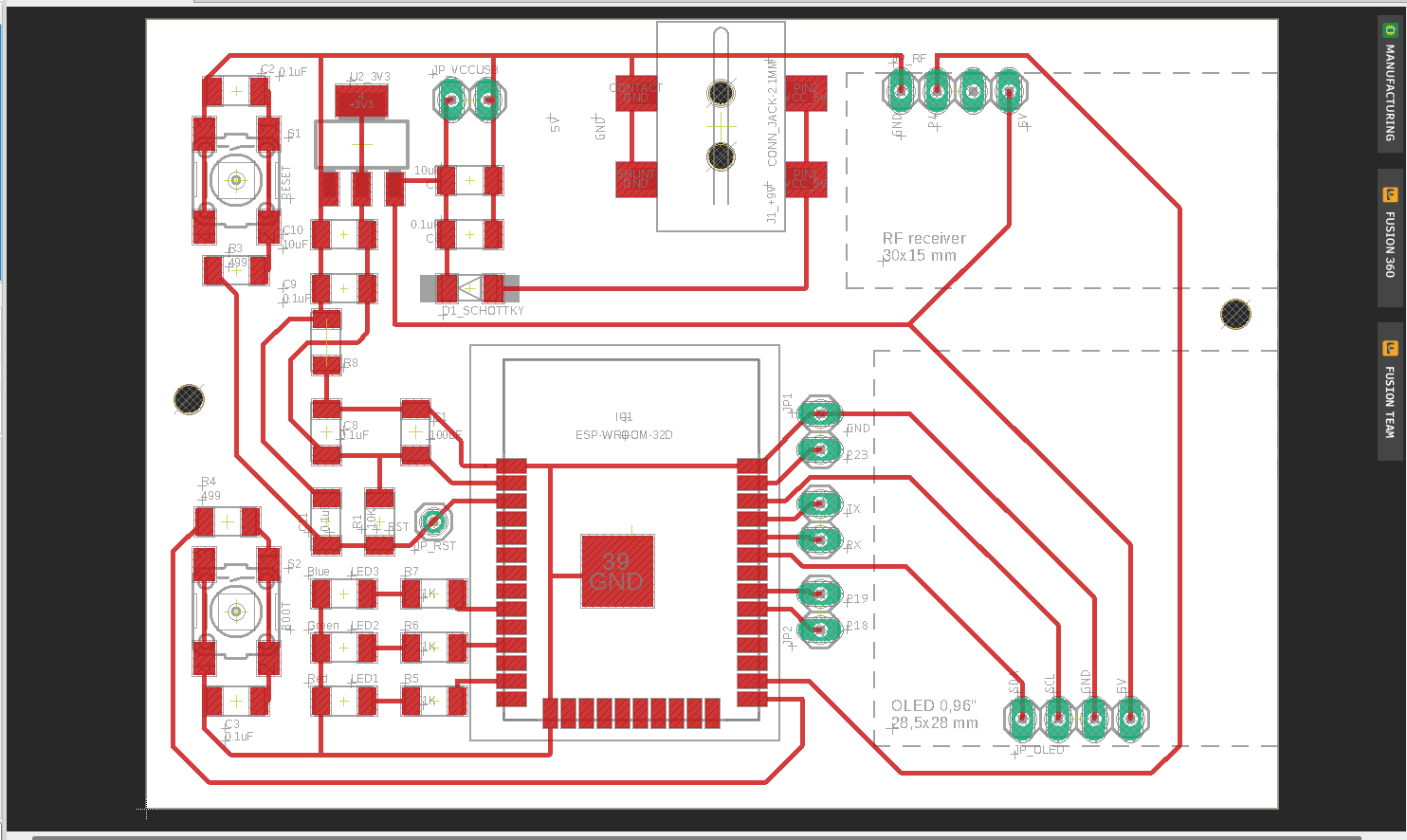 Board 2: new board design
B2: COMPONENTS | Electronics
- Radio receiver 433 MHz
- OLED display
- Capacitors, resistors and pin heads
- LEDs: green, red and blue
- Switches (Reset and Flash)
- Microcontroller ESP32 with WiFi module
- Voltage regulator, 3.3V output
- Power supply: Plug-in power supply (5V) and DC connector jack
- Circuit board
I leave out some components that are not necessary and correct the component list.
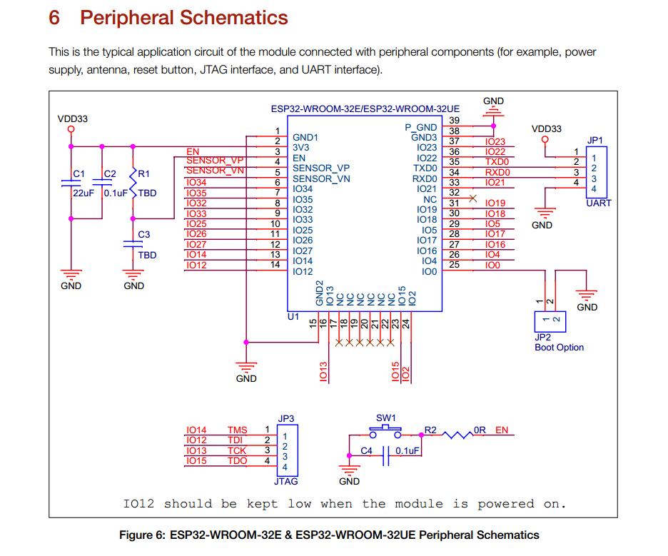
As reference for this I take this schematic from espressif for an ESP32-DevKitC.
x Voltage regulator, 5V output
x Capacitors and resistors
B2: VENDORS | COST
Here is the parts list for the second board. This board should cost about 19 €. In addition, there are costs for the batteries, the prototyping board and the use of the CNC machine.
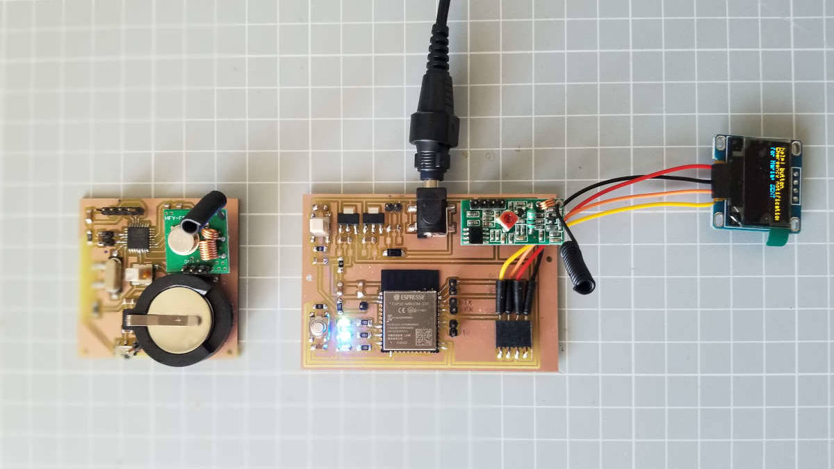
B1 + B2: Test with the two boards
Finally I can test the two boards together. Since I don't have any button batteries anymore, I first have to power the first board with a USB connection. The display looks slightly blurred because one corner of the screen is broken. New batteries and display will be delivered shortly.
I find a loose contact, which I solder again and then it works quite well. Every time the help! Hub receives Rf data, it flashes blue and sends an email. With the reset button the ESP32 restarts. I will optimize the screen display (shorten) and when sending the email the green LED should go off.
 help! button + help! hub
 help! button + notification
 Download
Board 1: help! button
- Eagle (.sch und .brd)
- Images for milling (.png)
Board 2: help! hub
- Eagle (.sch und .brd)
- Images for milling (.png)