WIRELESS COMMUNICATION
First, I read about wireless technologies to understand, which technology is more suitable for my project.
And what are its most important features.
I need to define the communication between the help! button and the hub AND how it connects to the Internet.
Feedback:
My instructor, Lena Hagenauer, told me to research about the ESP32 and the option to send an email from it. In addition, I have to check if the license-free radio frequency 433 MHz can be used for my project.
The next step is to define the wireless technology (what makes sense for my project and application) and do some testing.
WIRELESS DESIGN
I want to add wireless capabilities to my project, but don’t know where to start. What wireless technology do I need for my project? I followed these guidelines to get started with the design process:
Specify the project:
A emergency notification system that triggers an alarm and notifies other people or the police via email. It has a help! button for personal protection as part of a prevention system.
The system has 3 parts:
(1.) the help! button that sends data to the
(2.) hub, which has internet access and
(3.) sends the email via an interface or code.
More project specifications here: Idea + Parts, and Board + Design.
Specify features:
- Range: 0 – 20 meters | Tests are needed to define the range.
- Environment: indoor | There is probably not a good line of sight, e.g. reinforced concrete walls.
- Link: point-to-point | Point 1 is the help! button, point 2 is the hub with an internet connection module.
- Type of information: analog | Information source is the button + radio frequency (RF) waves.
- Data rate: Low | The throughput is not defined yet.
- Network: a simple P2P link
- Security: Not yet defined. | The wireless link does not involve critical data.
- Protocol: Not yet defined. | Bluetooth or Wi-Fi
- Power consumption: the help! button is portable and hub is fixed.
Pick a technology: 433MHZ + WiFi
After reading and comparing Bluetooth, Wi-Fi and 433 MHz band, I decide that the help! button and hub will communicate via the 433 MHz band. The hub will also have a Wi-Fi module.
Explanation:
- I only want to send small amounts of data between the h! button and the hub.
- These radio modules allow one-way communication over a reasonable distance.
- They are very cheap and tiny and are mostly used in games or toys.
- There is also an option to connect an external antenna to empower the performance/range.
STAYING LEGAL | REGULATIONS
The transmitter and receiver must comply with the regulations (regarding unlicensed radio transmitters) of the country in which it is used. Each country has an institution responsible for radio communications. In Germany, this is the Bundesnetzagentur.
On the page General Allocations you will find a PDF file about Short Distance Devices (SRD).
Here is also the link for the ‘Frequency Plan’: The 430 – 440 MHz frequency range for SRD is on page 281.
RADIOHEAD LIBRARY
To get started, I read through the RadioHead instructions and code examples using ASK communication. RH_ASK works with a range of low-cost ASK (amplitude shift keying) RF transmitters and receivers.
The library provides a complete object-oriented library for sending and receiving packetized messages over a variety of common data radios and other transports on a range of embedded microprocessors. Before you start coding, download the zip file and add the library to the Arduino IDE.
Amplitude Shift Keying (ASK)
ASK is a type of amplitude modulation that represents binary data in the form of amplitude variations of a signal. Simple RF modules (transmitter and receiver) use ASK modulation. ASK is suitable for low data rates and works reliably for slow data transmissions.
More about this in this tutorial: Amplitude Shift Keying
CODE PART 1: RF 433 MHZ Link
Board 1: Transmitter, Arduino UNO, ATmega328P
Board 2: Receiver, Arduino UNO, ATmega328P
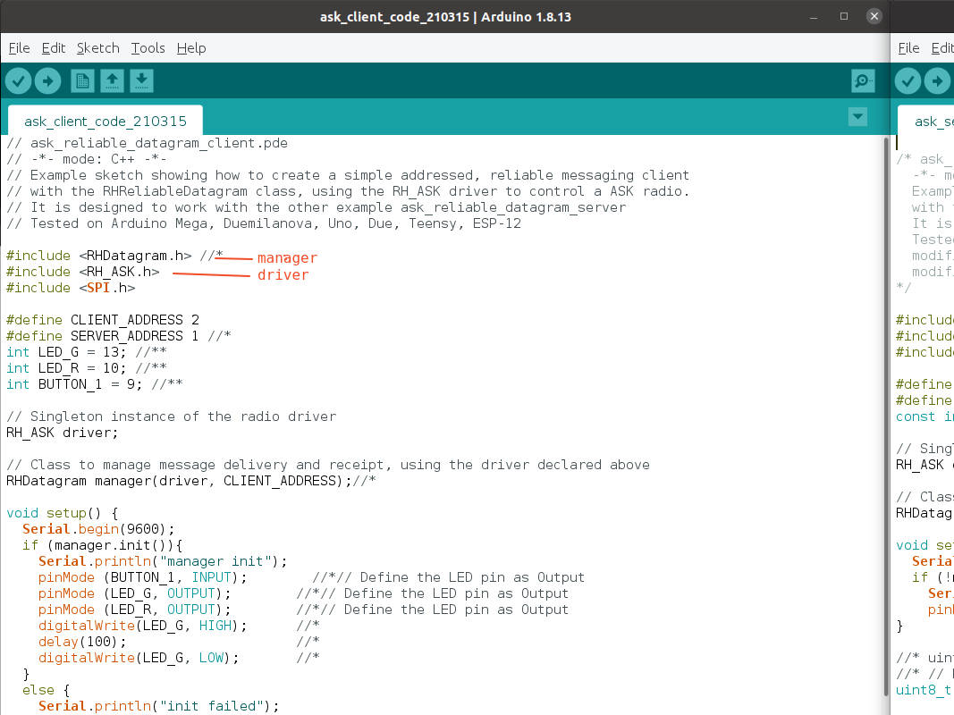
According to the description of the library, it has 2 sets of classes: Drivers and Managers. The RH_ASK driver sends and receives unaddressed, unreliable datagrams via ASK transmitter/receiver.
I want to address the receiver, so I include a manager class in the code. I took the Radio-Head example codes 'ask_realible_datagram_client' and 'ask_realible_datagram_server' and adapted them. I changed the RHReliableDatagram manager TO RHDatagram Manager because the communication is simple and only one-way.
Changes on the transmitter code:
RHReliableDatagram manager → RHDatagram manager
manager.sendtoWait → manager.sendto
and delete the reply-from-server function:
manager.recvfromAckTimeout.
Changes on the receiver code:
RHReliableDatagram manager → RHDatagram manager
manager.recvfromAck → manager.recvfrom
and commented out the reply-back-to-client function: manager.sendtoWait.
BOARDS
For the first code tests I order this RF Link kit according to the RF regulations in Germany: DEBO 433 RX/TX Entwicklerboards. The kit costs 2€. Datasheet | Pinout circuit
TRANSMITTER:
- Voltage 3.5-12V, voltage influences the range
- Power: 10mW
RECEIVER:
- Voltage: 5V DC
- Antenna: 32 cm single core wire, heliciform shaped.
NOTE
In the code, the transmitter is the client, and the receiver is the server.
RESULT
The code with the simple RF boards and the RHDatagram manager is working. But the 2€ boards don’t work well without antenna. So I order these modules as well to test them.
ANPRO 433 MHz Empfänger und Funk Sende Modul.
The range is much better: up to 20 m.
DOWNLOAD
CODE part 1: sketches (.ino) for transmitter and receiver.
CODE PART 2: adding LEDs and button
Board 1: Transmitter, Arduino UNO, ATmega328P
Board 2: Receiver, Arduino UNO, ATmega328P
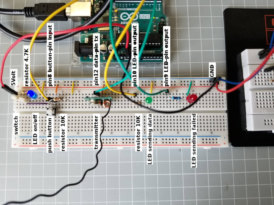
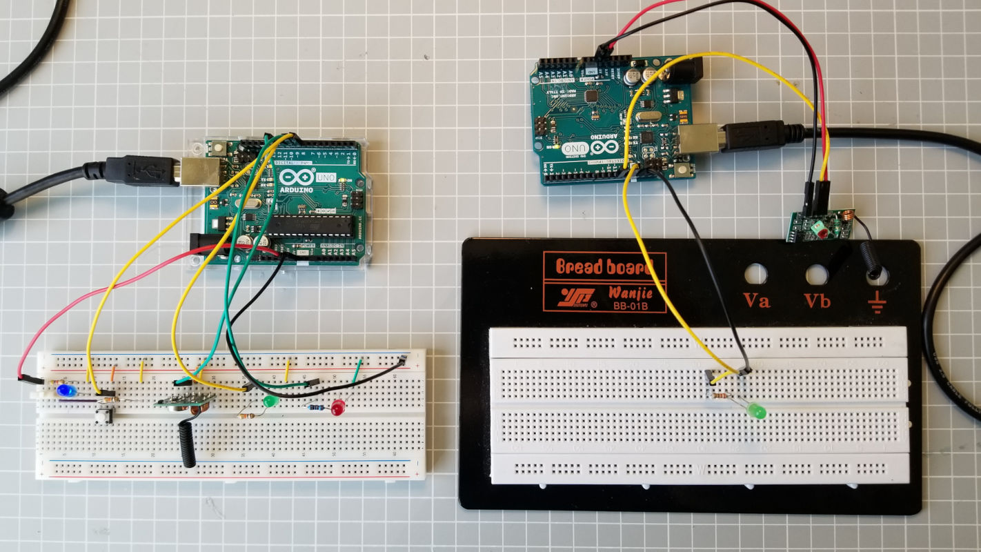
I added some LEDs on the breadboard for visual signals. I take my code from the networking week for the blinking LED (on the slave board) and the push button and integrate it into the code.
The transmitter has a blue or orange LED for power supply, a green LED for sending data and a red LED for error when sending data.
The receiver has a orange LED for power supply, a green LED for receiving data, a red LED for error when sending the email and a blue LED when sending the email was successful.
RESULT
This part works well, I have no problems with the code or the circuit.
DOWNLOAD
CODE part 2: sketches (.ino) for transmitter and receiver.
Testing the code part 2: sending data
Testing the code part 2: testing the range
CODE PART 3: RF communication code on other boards
Board 1: Transmitter, Arduino UNO, ATmega328P
Board 2: Receiver, Arduino MKR 1010 or ESP32
The receiver must have WiFi functionality. That's why I'm testing the RF communication code with the RadioHead library on these two boards: Arduino MKR WiFi 1010 and DOIT ESP32 DEVKIT V1.
Arduino MKR WiFi 1010
The MKR WiFi 1010 is a board designed for IoT projects. It has WiFi and Bluetooth functionality. More specifications
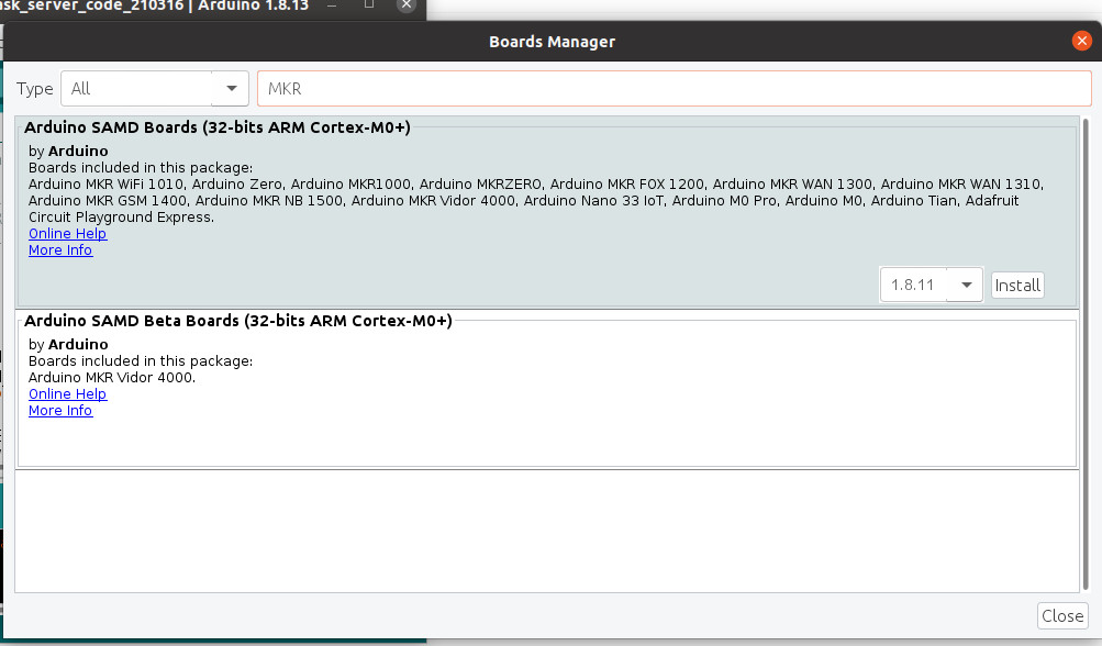
To get started, include the MKR 1010 WiFi board in the Arduino Boards Manager.
Go to
Menu > Tools > Boards manager > Choose Arduino SAMD Boards
→ Choose the board and compile the code.
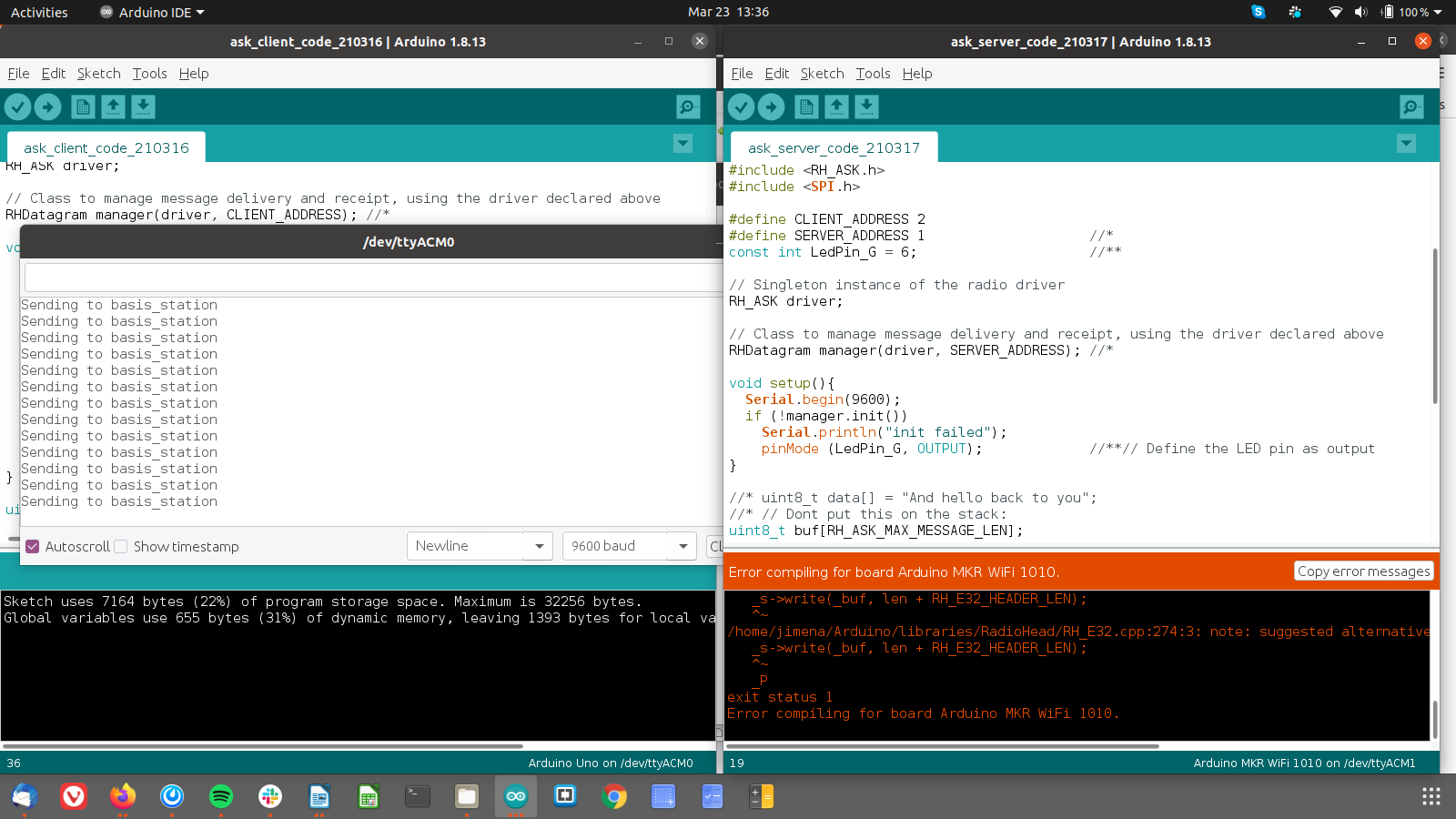
NOTE / ERROR
the code can not be compiled, I checked the pinout of the MRKWiFi1010 and changed the pin numbers in the library, but without success.
CONCLUSION
the RadioHead library works on many Arduino boards (tested on Arduino Mega, Duemilanova, Uno, Due), but not yet on the MKRWiFi1010. After some tries, I decide to test the code on the ESP32.
ESP32
The ESP32 board offers a WiFi and Bluetooth interface for a wide-range of applications. More specifications. I will use this board with 36 GPIOs 'DOIT ESP32 DEVKIT V1.There are also ESP32 boards with 30 GPIOs.
So far I have had no experience with this board. After researching about the ESP32, I find this tutorial to start with. It has a very good description about the specifications of the boards, a pinout guide and a start code to blink the built-in LED. Getting started.
ESP32 + Arduino IDE
First, I have to add the ESP32 board in the Arduino Boards Manager. Open this page: Arduino core for the ESP32 and go to Instructions for the Arduino IDE Boards Manager and copy the URL into the Arduino Preferences windows as described. Then I follow the steps described in the tutorial and I can upload the ‘Blink’ code successfully and the built-in LED is blinking. Don’t forget to select the correct board, in my case, I need to select DOIT ESP32 DEVKIT V1.
NOTE 1 ERROR
Error compiling for board DOIT ESP32 DEVKIT V1
I look for the error mentioned. After reading about similar errors, I understand that the directory path for the Arduino sketch should not have spaces. I have fixed this problem and can upload my first sketch.
NOTE 2
Upload a code: To put the board into upload mode, press the RST and FLASH buttons simultaneously.
NOTE 3
Receiver module needs 5 V1: The ESP32 module only works with 3.3V, 5V can damage it. But the RF receiver board works only with 5V. When I design the board, I have to include a voltage regulatorin the board design.
CODE
Now I want to use my code for the receiver on the ESP32. I need to modify the code by
- changing the upload speed (to 115200),
- commenting out the default RH_ASK driver
- commenting the driver for the ESP32 with the correct pin settings and
- changing the pin number for the LED pin (output).
RESULT
There is one main difference that I noticed: For the ESP32 to get the data, the button on the transmitter must be held for at least 1 second. This was much faster with the Arduino UNO as receiver. Immediately after pressing the button quickly, the Arduino receiver obtained the data. Unfortunately I could not find out why the ESP32 receives the data 'slower'.
NEXT STEPS
- Code on the server/receiver board: If data was received → send an email or message
- If the email was sent → start the sound and visual alarm , LED
DOWNLOAD
CODE part 3 : sketches (.ino) for transmitter (Arduino Uno) and receiver (ESP32).
CODE PART 4: WiFi connection and email
Board 1: Transmitter, Arduino UNO, ATmega328P
Board 2: Receiver, DOIT ESP32 DEVKIT V1, ESP-WROOM-32
The RF communication code worked well on the ESP32, so I continue to use it for the next steps. The ESP32 will connect to an existing WiFi network to send the email or message.
WIFI
In this part, I will connect the hub to a WiFi network. After that I will try to send an email or message, e.g. Telegram. I will take the basics of connecting to a WiFi network from this tutorial: 'Connecting to a WiFi network'.
First I have to include the library WiFi.h and then I enter the credentials (ssid and password) of the WiFi network into the code. The SSID is the Service Set Identifier = the name of the network.
NOTE
About the code: ! is a logical NOT for the WHILE loop. As long as the ESP32 is NOT connected to the WIFI network, ‘Connecting to WiFi’ is printed on the serial monitor.
RESULT
The ESP32 connects to the WiFi network. It takes about 3.5 seconds to establish the connection.
SENDING THE NOTIFICATION EMAIL
Now I want to send a notification email to a person or to the police. The next step is to connect the ESP32 to a STMP server. The Simple Mail Transfer Protocol (STMP) is a protocol of the Internet protocol family used to exchange e-mails in computer networks. I will follow the steps described in this tutorial to set up the code to send emails: Send Emails using an SMTP Server.
INSTALLING THE LIBRARY
The library ESP32 MailClient enables ESP32 to send emails with/without attachment and receive emails with/without attachment download via SMTP and IMAP servers.
To install the library > Go to Sketch > Include Library > Manage libraries
and search for ‘ESP32 Mail Client‘ by Mobizt > select ‘Install’.
SETUP THE SENDER EMAIL
I will create a new Gmail account to test this part of the code. Do not use your private email, it may be blocked. For the sender email you can use any email provider, I just chose Gmail. The email recipient is the person who wants to be notified or the police.
After creating the account, go to your account settings > security > access through less secure apps
> allow less secure apps: ON
GMAIL SMTP SERVER SETTINGS
If you use a Gmail account, this is the SMTP server information. Different email providers have different SMTP server settings. But you can easily find them if you search for them.
CODE:
Modifications:
- I changed the global variables like SSDI and the password and added the correct sender email settings (account, password) and the main recipient. I deleted some lines of code that I don't need.
- The subject is now: ‘Emergency Notification’.
- I also changed the HTML text and viewed it on this page. HTML online editor.
- Finally, I add a recipient: the email should be sent to 2 at least 2 people.
smtpData.addRecipient("emailRecipient");//the first email is defined at the beginning of the code.
smtpData.addRecipient("recipient2@gmail.com");
NOTE:
The WiFi.h library does not need to be included. You can use the ESP32_MailClient.h library to connect the ESP32 to WiFi.
RESULT:
- the synchronization on my desktop (Thunderbird) is faster (4 seconds) than the synchronization with the Gmail app on my phone (2.5 minutes!). I’m going to check this.
- First, I changed some app settings on my phone: Remove Gmail from the battery optimization list and allow all notifications. I also changed the sound for the Gmail notifications.
- Then I changed these Gmail account settings: show only 25 emails or less, disconnect from Hangout, and disable filters . For me, it is also important to receive a notification fevery time someone pressed the help! button. Please uncheck ‘Conversation View’ in account settings.
NOW I receive every email on my phone almost simultaneously with my laptop, about after 3 seconds. The ESP32 connects to the WiFi network and then sends the emergency email in 11 seconds.
NOTE
ERROR: If the e-mail password is incorrect, this text appears in the serial monitor (-> screenshot).
DOWNLOAD
CODE: sketch (.ino) for the hub (ESP32): WiFi connection and send email.
MERGE code part 3 (433MHz) and part 4 (WiFi)
First I try this simple code on the ESP 32: when I push the button, the board reads the voltage input, the red LED blinks three times and stays on. RESULT: the code worked and the LED stays on. To turn the LED off, you have to reset the board.
Then I include the fourth code to send the mail via WiFi in the third code to receive the data via 433 MHZ frequency. In the first part I include the libraries, set the constants for the pin numbers and the network credentials and define some values for the client/srver address and the SMTP server setup.
Setup: the speed for the serial communication and the pin mode are set. The manager for the RF communication is started and the board connects to the WiFi network. The messages for the serial monitor have debugging purpose. I added two LEDs to know if the ESP32 connected to the WiFi network (green LED) or there is an error (red LED). The setup part runs only once.
The loop runs every time the button on the transmitter is pressed and the ESP32 receives data. The blue LED blinks when data is received. After that, all functions for the SMTP server run to send the email.
Finally, you can read on the serial monitor whether the e-mail was sent successfully. In that case the blue LED is on. If there is an error, you would see it on the serial monitor or the red LED would light up. To turn off the LEDs, you need to press the reset button on the board and the board will reconnect to the WiFi network.
NOTE:
About the code: in the setup part, I add BREAK in the while loop to stop the connection attempt to the WiFi network after 20 seconds.
Transmitter
/* ask_reliable_datagram_client.pde
 *  http://www.airspayce.com/mikem/arduino/RadioHead/examples.html
 *  ask_reliable_datagram_client.pde example code:
 *  modified J.Gálvez 12.03.21:
 *    (*) changed manager to RGDatagram.
 *    (**) LEDs and pushbutton added
*/


#include "RHDatagram.h"                     //*
#include "RH_ASK.h"
#include "SPI.h"

#define CLIENT_ADDRESS 2
#define SERVER_ADDRESS 1                    //*
const int LedPin_G = 10;                    //**
const int LedPin_R = 9;                     //**
const int ButtonPin = 8;                    //**

// variables will change:
int buttonState = 0;                        //*** variable for reading the pushbutton status

RH_ASK driver;                             // Singleton instance of the radio driver

// Class to manage message delivery and receipt, using the driver declared above
RHDatagram manager(driver, CLIENT_ADDRESS); //*

void setup() {
  Serial.begin(9600);
  if (manager.init()){
    Serial.println("manager init");
    pinMode (ButtonPin, INPUT);             //**// Define the pushbutton pin as an input
    pinMode (LedPin_G, OUTPUT);             //**// Define the LED pin as output
    pinMode (LedPin_R, OUTPUT);             //**// Define the LED pin as output
    digitalWrite(LedPin_G, HIGH);           //**
    delay(100);                             //**
    digitalWrite(LedPin_G, LOW);            //**
  }
  else {
    Serial.println("init failed");
  }
}

uint8_t data[] = "Emergency!";              //*
uint8_t buf[RH_ASK_MAX_MESSAGE_LEN];       // Dont put this on the stack:

void loop(){
  buttonState = digitalRead(ButtonPin);     //*read the state of the pushbutton value:
  // check if the pushbutton is pressed. If it is, the buttonState is HIGH:
  if (buttonState == HIGH) {
    manager.sendto(data, sizeof(data), SERVER_ADDRESS);
    Serial.println("Sending to basis_station"); //*turn LED on:
    digitalWrite(LedPin_G, HIGH);
    delay(500);
  }
  else {
    digitalWrite(LedPin_G, LOW);                //** turn LED off:
  }
}
Receiver: ESP32)
/* ask_reliable_datagram_server.pde
 *  http://www.airspayce.com/mikem/arduino/RadioHead/examples.html
 *  modified by J.Gálvez 12.03.21:
 *  (*1) changed manager to RGDatagram.
 *  (*2) LED added
 *  (*3) settings changed -> now for ESP32
 *  (*4) include modified code to send an email via WiFi/SMTP server.
 *  (example code @https://RandomNerdTutorials.com)
 *  modified by J.Gálvez 16.04.21:
 *  (*5) add time to connect to WiFi network; exit while loop
*/

#include "RHDatagram.h"                      //(*1)
#include "RH_ASK.h"

#define CLIENT_ADDRESS 2
#define SERVER_ADDRESS 1                    //(*1)
const int LedPin_B = 19;                    //(*2) blue LED for receiving RF data and email sent
const int LedPin_G = 18;                    //(*4) green LED for wifi connected and prepared for RF data
const int LedPin_R = 21;                    //(*4) red LED for error

// Singleton instance of the radio driver
RH_ASK driver(2000, 4, 5, 0);               //(*3) ESP8266 or ESP32: do not use pin 11 or 2

// Class to manage message delivery and receipt, using the driver declared above
RHDatagram manager(driver, SERVER_ADDRESS); //(*1)

#include "WiFi.h"
#include "ESP32_MailClient.h"               //(*4){

// REPLACE WITH YOUR NETWORK CREDENTIALS
const char* ssid = "yourNetwork";           //*replace it
const char* password = "yourPassword";      //*replace it

// To send Email using Gmail use port 465 (SSL) and SMTP Server smtp.gmail.com
// YOU MUST ENABLE less secure app option https://myaccount.google.com/lesssecureapps?pli=1
#define emailSenderAccount    "EXAMPLE_EMAIL@gmail.com"           //*replace it
#define emailSenderPassword   "YOUR_EXAMPLE_EMAIL_PASSWORD"       //*replace it
#define emailRecipient        "YOUR_EMAIL_RECIPIENT@EXAMPLE.com"  //r*eplace it
#define smtpServer            "smtp.gmail.com"
#define smtpServerPort        465
#define emailSubject          "youSubject"

// The Email Sending data object contains config and data to send
SMTPData smtpData;

// Callback function to get the Email sending status
void sendCallback(SendStatus info);             //(*4) }


void setup(){
  Serial.begin(115200);
  byte i = 0;
  pinMode (LedPin_B, OUTPUT);                   //(*2)// Define the LED pin as output
  pinMode (LedPin_G, OUTPUT);                   //(*4)// Define the LED pin as output
  pinMode (LedPin_R, OUTPUT);                   //(*4)// Define the LED pin as output

  if (!manager.init()){
    Serial.println("init failed");
  }

  WiFi.begin(ssid, password);                   //(*4) {
  while (WiFi.status() != WL_CONNECTED) {
    Serial.println("Connecting...");
    digitalWrite(LedPin_G, HIGH);               //(*4)error: cannot connect to WiFi
    delay(500);
    digitalWrite(LedPin_G, LOW);
    delay(500);
    Serial.printf(" %i sec\n", i);
    if (++i > 11) {
      Serial.print("\nVerbindung zum AP fehlgeschlagen !\n\n");
      break;
    }
  }

  if (WiFi.status() != WL_CONNECTED) {
    digitalWrite(LedPin_R, HIGH);
    digitalWrite(LedPin_G, LOW);
    Serial.println();
    Serial.println("WiFi connection failed.");
  }
  else{
    digitalWrite(LedPin_R, LOW);
    digitalWrite(LedPin_G, HIGH);                 //(*4)// setup without errors
    Serial.println();
    Serial.println("WiFi connected.");
    Serial.println();
    Serial.println("Prepared for receiving data and sending e-mails");
    Serial.println();                             //(*4) }
  }

}

uint8_t buf[10];                                //(*3) Message length

void loop(){
  if (manager.available()){
    Serial.println("RF manager available");
    uint8_t len = sizeof(buf);                   // Wait for a message addressed to us from the client
    uint8_t from;
    if (manager.recvfrom(buf, &len, &from)){     //(*1)
      Serial.print("got request from : 0x");
      Serial.print(from, HEX);
      Serial.print(": ");
      Serial.println((char*)buf);
      digitalWrite(LedPin_B, HIGH);             //(*2)
      delay(200);
      digitalWrite(LedPin_B, LOW);              //(*2)
      delay(200);
      digitalWrite(LedPin_B, HIGH);             //(*2)
      delay(200);
      digitalWrite(LedPin_B, LOW);              //(*2)
      delay(200);
      digitalWrite(LedPin_B, HIGH);             //(*2)
      delay(200);
      digitalWrite(LedPin_B, LOW);              //(*2)
      delay(200);
      digitalWrite(LedPin_R, LOW);              //(*2)

      // Set the SMTP Server Email host, port, account and password     //(*4) {
      smtpData.setLogin(smtpServer, smtpServerPort, emailSenderAccount, emailSenderPassword);
      // For library version 1.2.0 and later which STARTTLS protocol was supported,the STARTTLS will be
      // enabled automatically when port 587 was used, or enable it manually using setSTARTTLS function.
      //smtpData.setSTARTTLS(true);
      // Set the sender name and Email
      smtpData.setSender("Emergency_Notification", emailSenderAccount);
      // Set Email priority or importance High, Normal, Low or 1 to 5 (1 is highest)
      smtpData.setPriority("High");
      // Set the subject
      smtpData.setSubject(emailSubject);
      // Set the message with HTML format
      smtpData.setMessage("...", true);                                    //(*4) add you message
      // Set the email message in text format (raw)
      //smtpData.setMessage("Hello World! - Sent from ESP32 board", false);
      // Add recipients, you can add more than one recipient
      smtpData.addRecipient(emailRecipient);                    //*the email you added above
      smtpData.addRecipient("jimena.galvez@gmx.de");              //*added one recipient
      //smtpData.addRecipient("YOUR_OTHER_RECIPIENT_EMAIL_ADDRESS@EXAMPLE.com");
      smtpData.setSendCallback(sendCallback);
      //Start sending Email, can be set callback function to track the status
      if (!MailClient.sendMail(smtpData)){
       Serial.println("Error sending Email, " + MailClient.smtpErrorReason());
       digitalWrite(LedPin_B, LOW);                                     //(*4) email NOT sent
       digitalWrite(LedPin_R, HIGH);
       }
      //Clear all data from Email object to free memory
      smtpData.empty();                                                 //(*4) }

    }
  }
  else {
  }
}

// Callback function to get the Email sending status                    //(*4) {
void sendCallback(SendStatus msg) {
  // Print the current status
  Serial.println(msg.info());

  // Do something when complete
  if (msg.success()) {
    Serial.println("----------------");
    digitalWrite(LedPin_B, HIGH);                                     //(*4) email sent successfully
    digitalWrite(LedPin_R, LOW);
  }
}                                                                     //(*4) }
RESULT
After a few attempts to merge the two codes, I figured it out. The order of the constants in the first part is not important. In the setup part, the ESP32 connects to the WiFi network, so it is ready to receive RF data.
For me as a user, it was important to understand what the ESP32 was doing, so I added the LEDs. With colored visual signs you can know if the emergency email was sent successfully or if there are any other problems.
DOWNLOAD
CODE: Sketch (.ino) for transmitter (help! button; ATmega328P) and receiver (hub, ESP32).
Testing the code part 4: sending the emergency email
Testing the code part 4: Error sending email, login password is not valid.
Testing the code part 4: Error, WiFi connection failed
CODE PART 5
UPDATE
Feedback from my instructor Tobias:
Board1: To reduce the size of the case, I should consider using coin cell batteries instead of 5 x AA batteries. It is also possible to add a sleep mode to the code to reduce power consumption.
Board 2: I should also add an display to read the message status, not only with LEDs.
ADD A DISPLAY
I have a 0,96” oled mini-display. First, I try the libraries ‘Adafruit SSD1306’ and ‘Adafruit GFX library’, but I get an error message that there is not enough program storage space on the chip. My instructor Lena recommends that I try the SSD1306Ascii library in the code because it is optimized and easy to use for simple text messages. Finally the program works without error messages.
DOWNLOAD
CODE: Sketch (.ino) for the receiver/server with display(hub, ESP32).

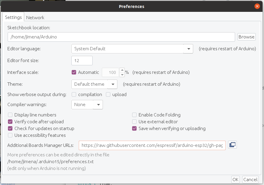 Additional Boards Manager
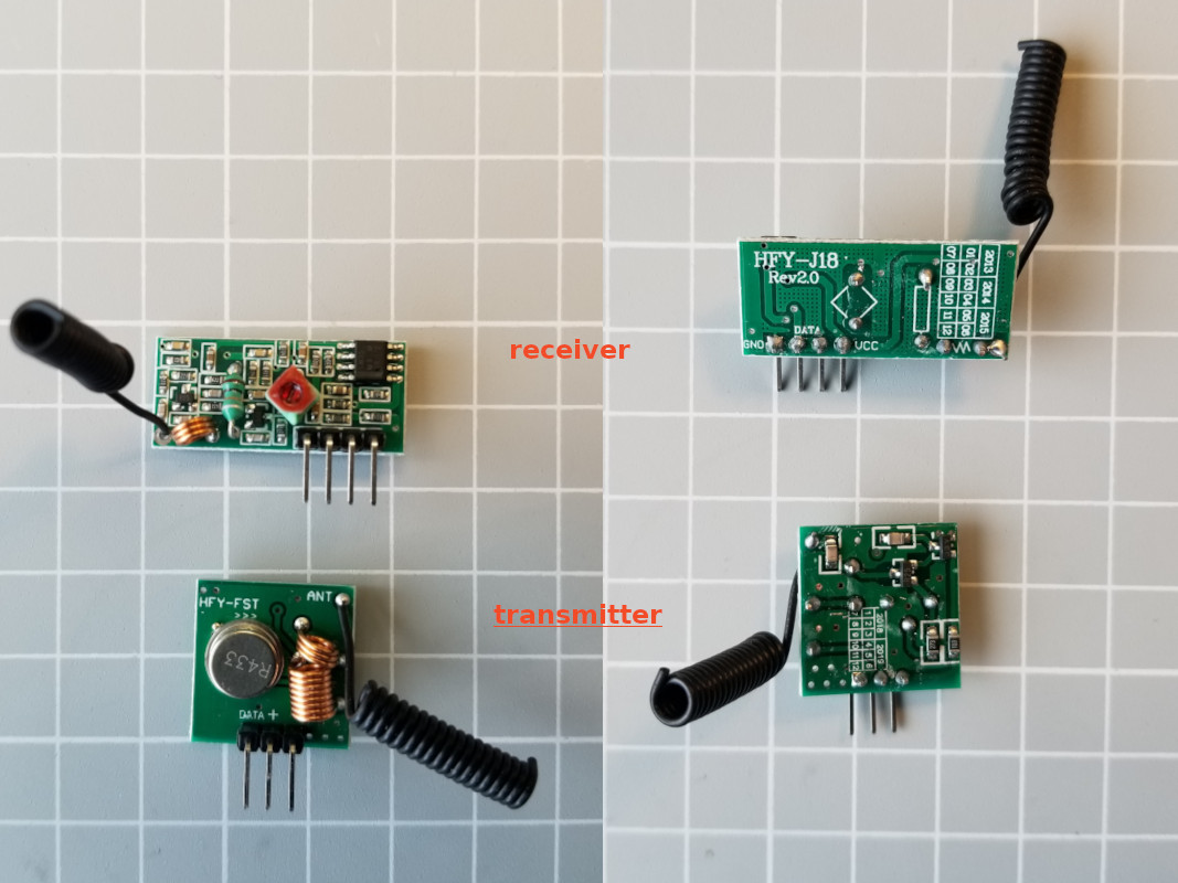 ANPRO RF boards
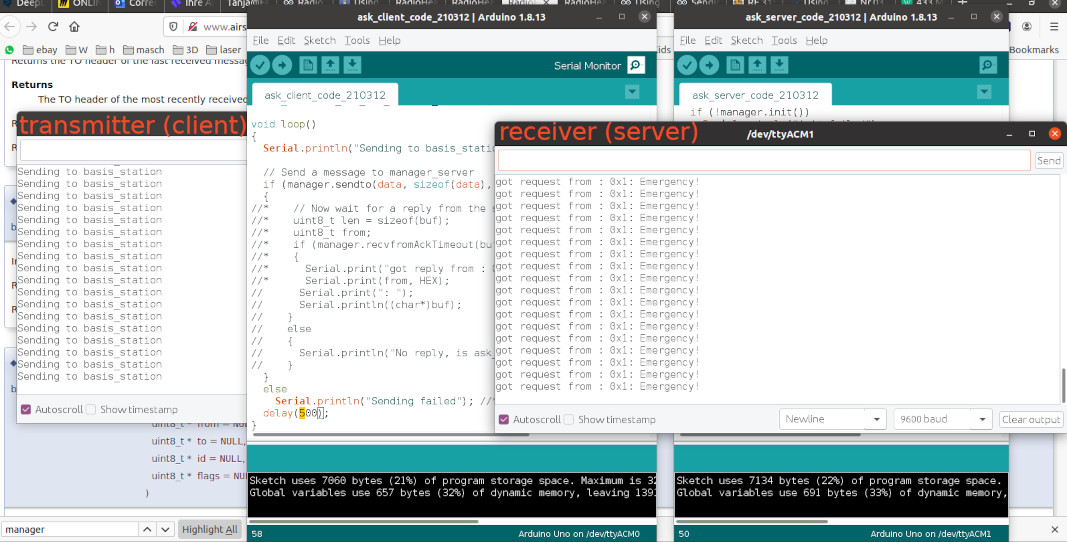 Data sent
 transmitter: breadboard circuit
 transmitter and receiver: breadboard circuits
 Install SAMD boards
 Error
Error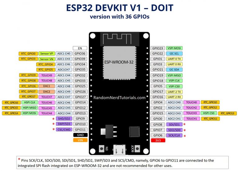 ESP32 pinout with 36 GPIOs @randomnerdtutorials.com
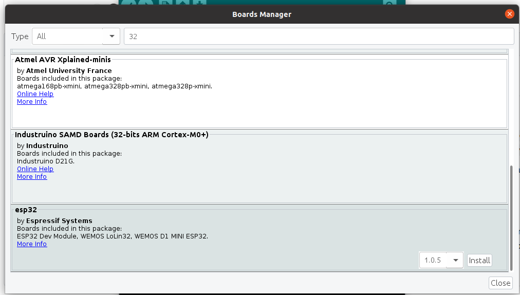 Install ESP32 boards
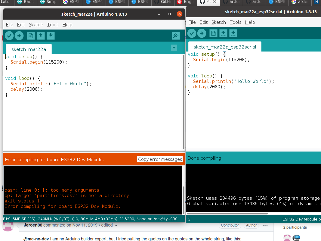 Error compiling
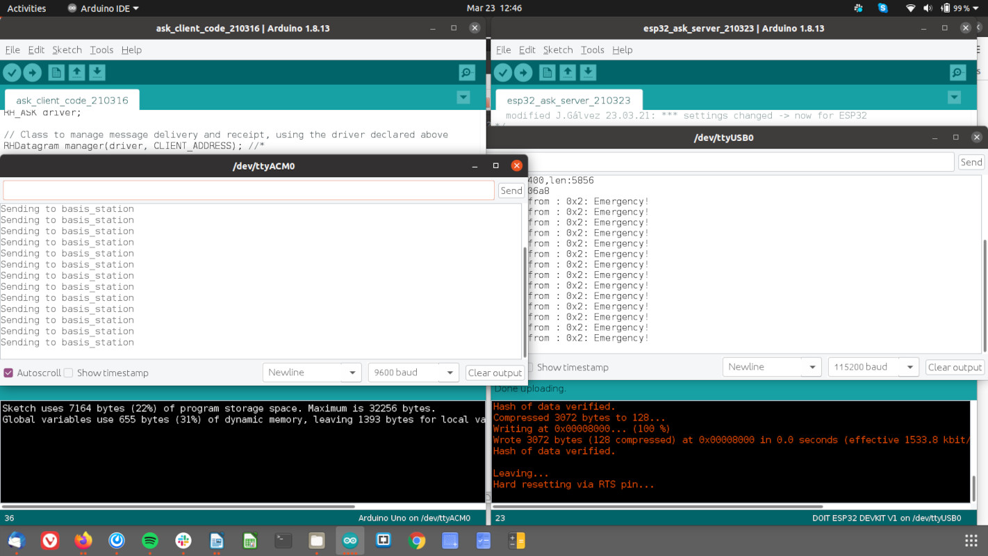 ESP32 receiving data
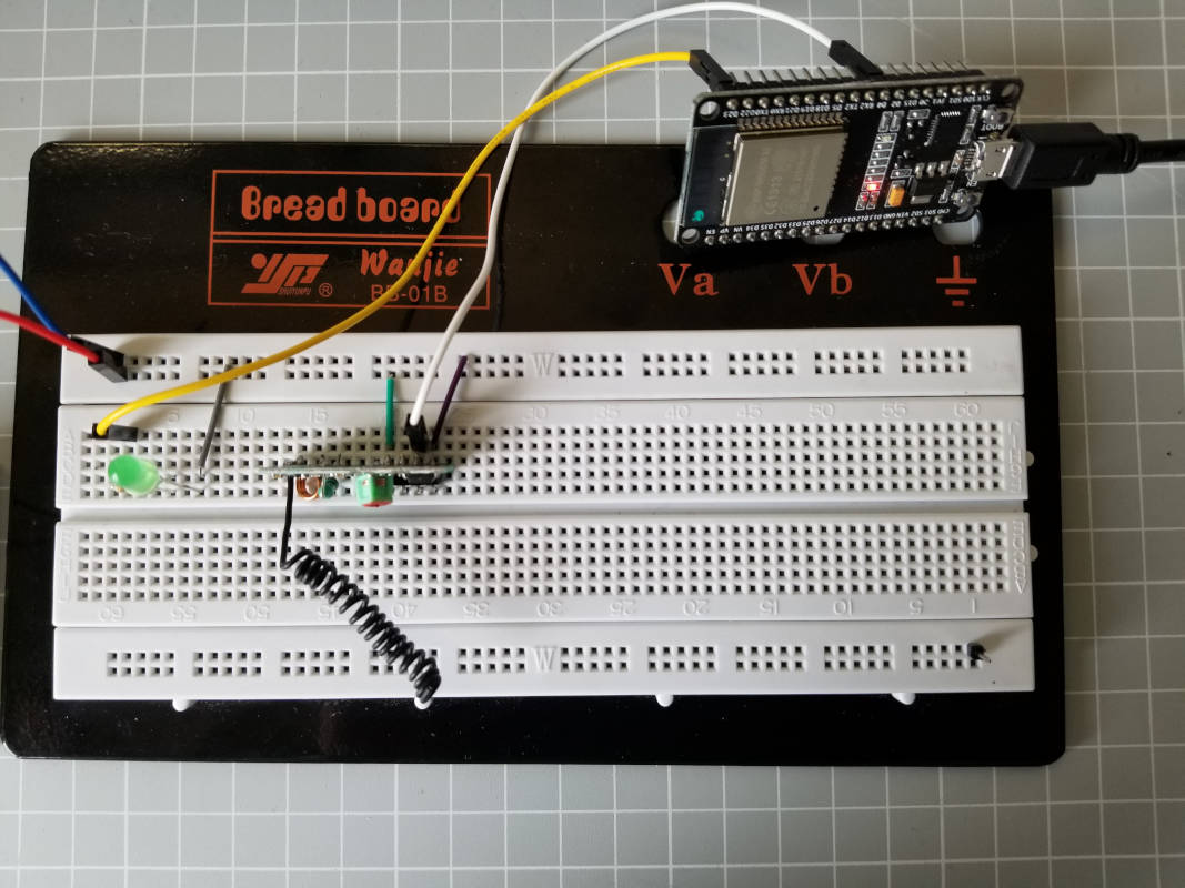 ESP32 receiving data
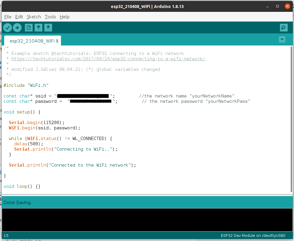 Code: connecting to WiFi
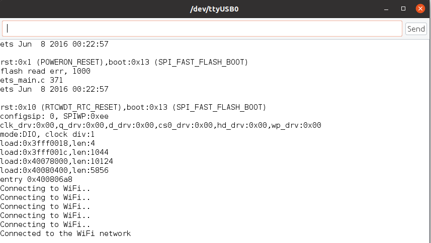 Code: connected to WiFi
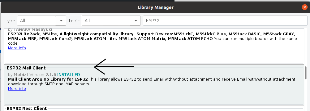 Manage libraries
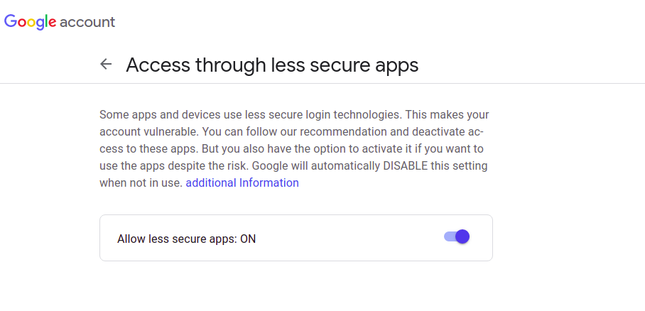 Gmail allow less secure apps
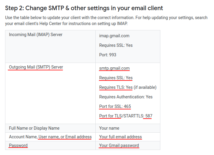 Gmail SMTP settings
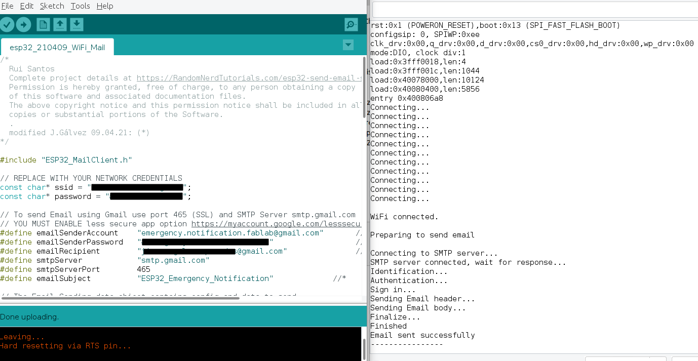 Code and serial monitor
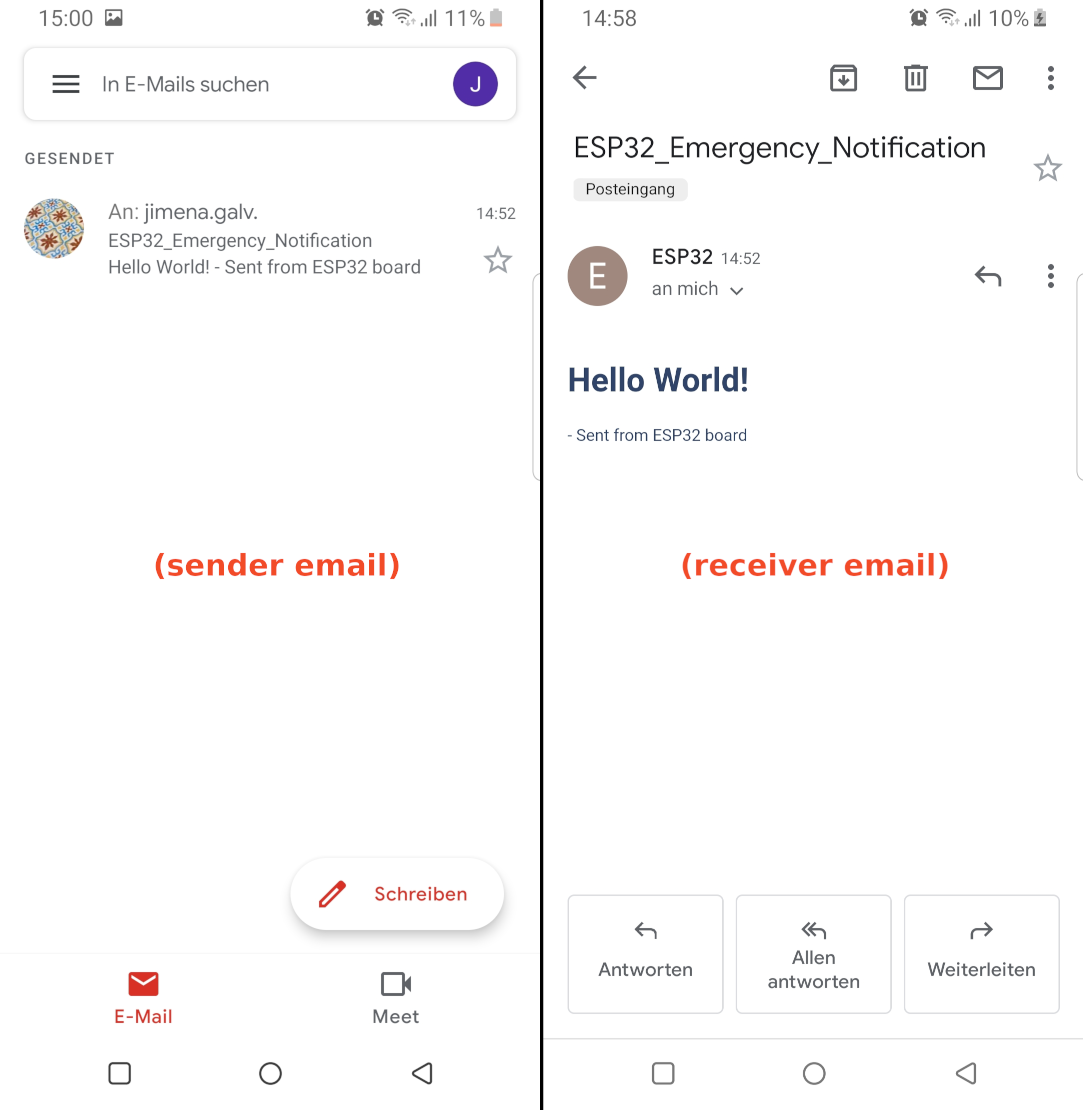 Email sent and received
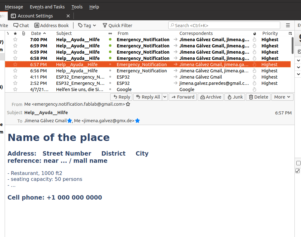 Email received
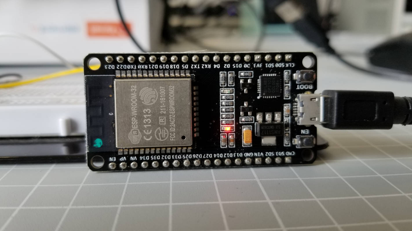 send an email with the ESP32
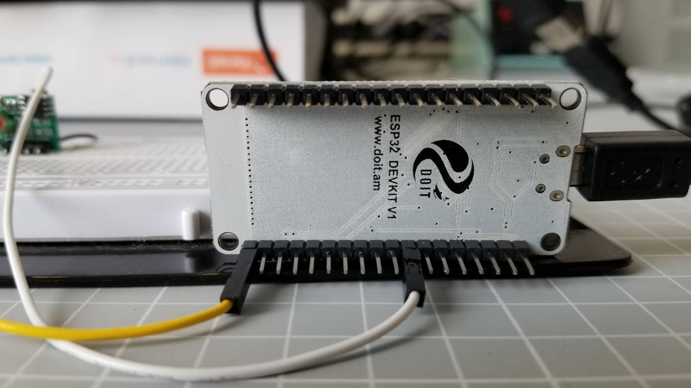 send an email with the ESP32
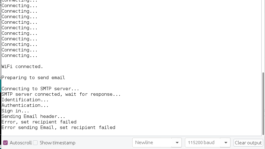 Error: password was wrong
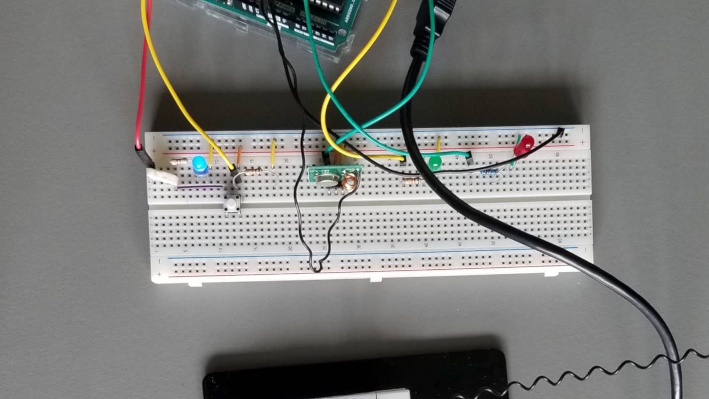 Emergency button / Transmitter / Arduino
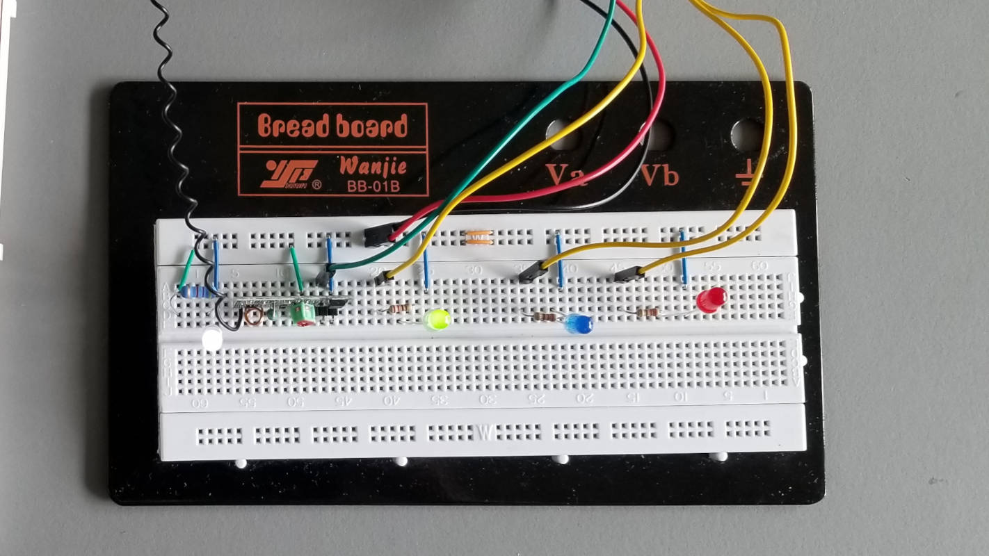 Base station / Receiver / ESP32
 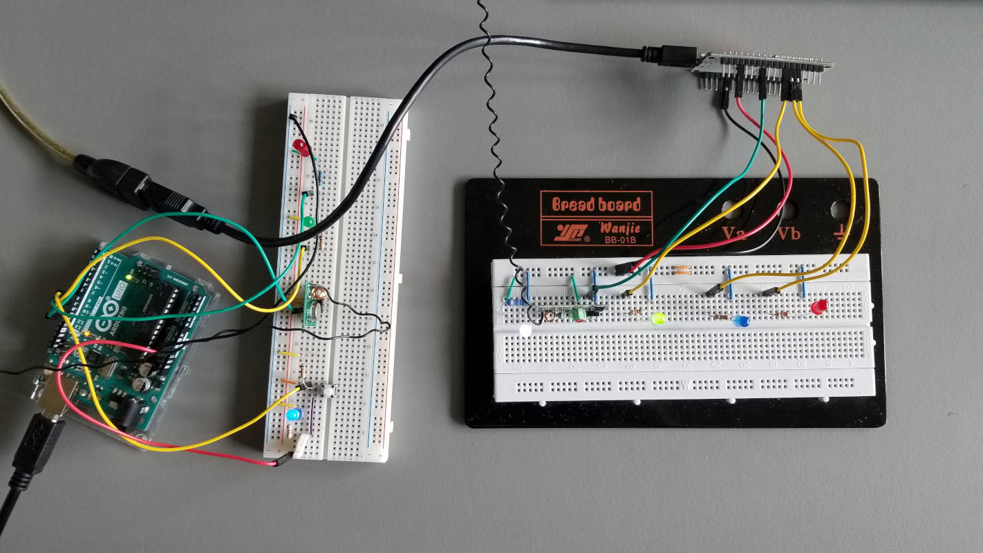 transmitter and receiver
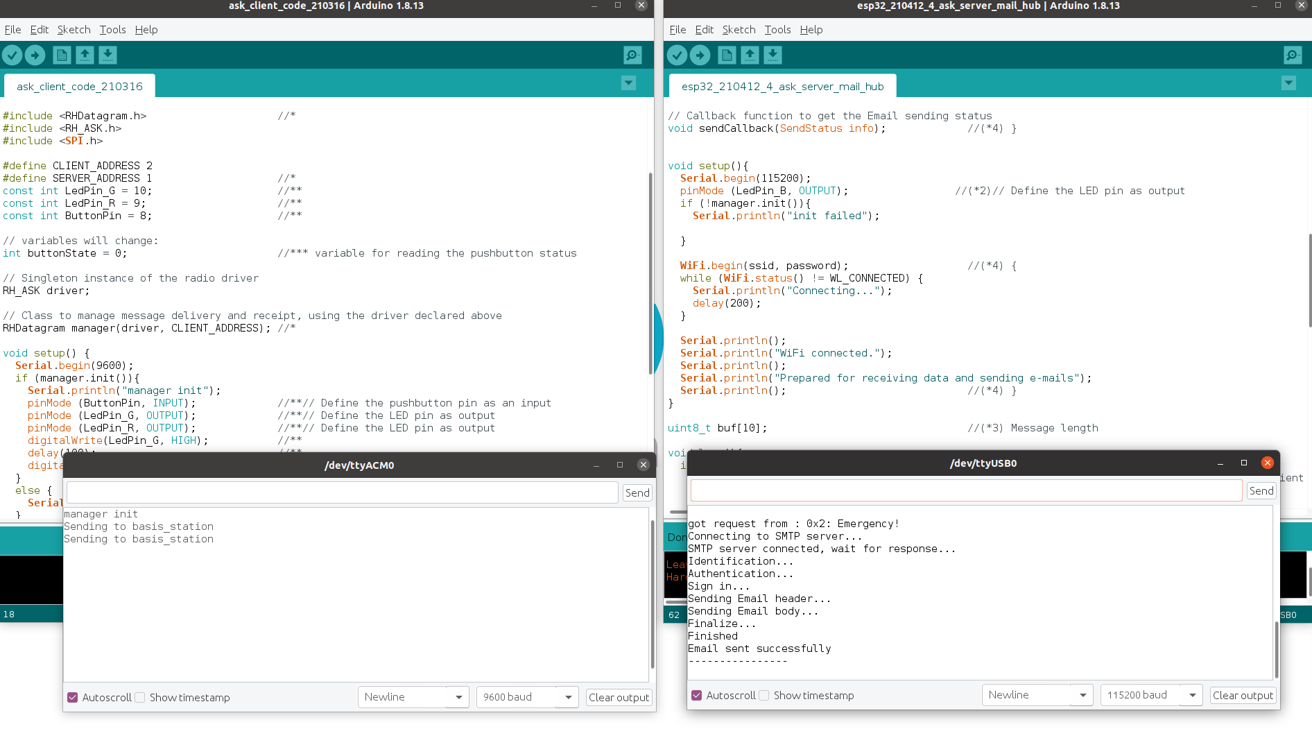 Serial Monitor of the two boards
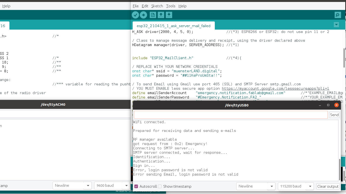 Error: password is not valid
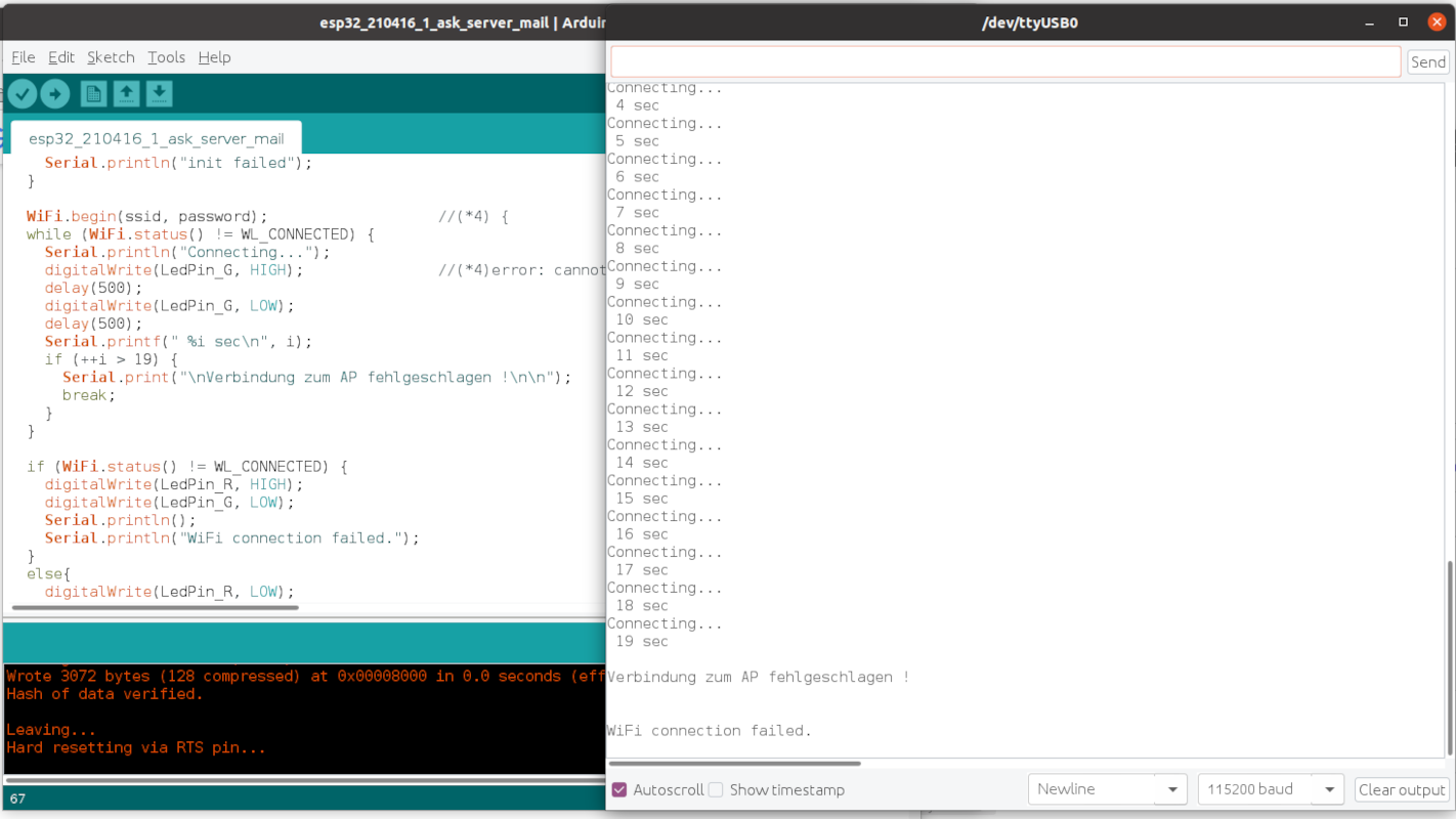 Error: WiFi connection failed