Shining Daisy Chains
++
#1_Asyncronism
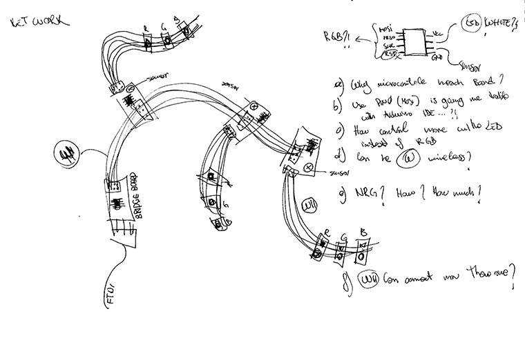
I choose to create a network of the board that design for output device week's. Step by step I will start from asynchronous connection to go on comparing it with the I2C and program it with arduino IDE.
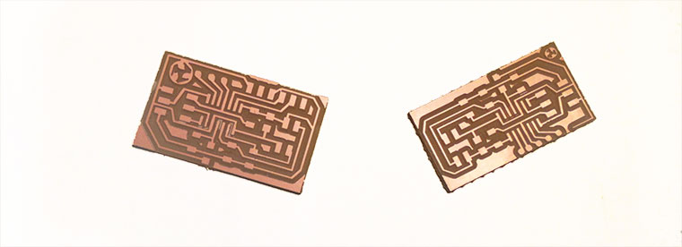
Each node have a light sensor, and an RGB LED connected re-using the MISO MOSI and SCK connection of the ISP Header, after programming. That meas actually one more pin compared with the board already design. For that reason I had to choose an Attiny 44 a make a new design.

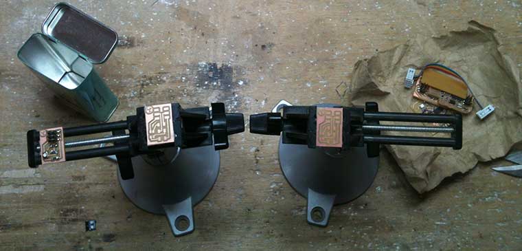
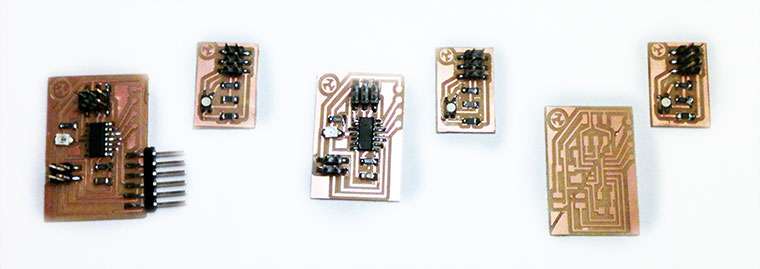
I milled with Roland Modela MDX controlled by fab modules, and soldered . A routine that can always reserve some issues.
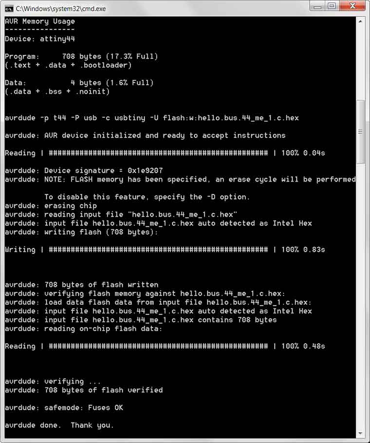
Than I try to program it using using the Hello.bus C program by Neil adapted to my attiny 44. I re-difined RX and TX pins design to correspond to Arduino's PIN0 and PIN1. Instead of Led-pin I defined 3 char called red, blue and green each one with his how pin , MOSI, MISO, and SCK .
#include
#include
#include
#include
#define output(directions,pin) (directions |= pin) // set port direction for output
#define input(directions,pin) (directions &= (~pin)) // set port direction for input
#define set(port,pin) (port |= pin) // set port pin
#define clear(port,pin) (port &= (~pin)) // clear port pin
#define pin_test(pins,pin) (pins & pin) // test for port pin
#define bit_test(byte,bit) (byte & (1 << bit)) // test for bit set
#define bit_delay_time 100 // bit delay for 9600 with overhead
#define bit_delay() _delay_us(bit_delay_time) // RS232 bit delay
#define half_bit_delay() _delay_us(bit_delay_time/2) // RS232 half bit delay
#define led_delay() _delay_ms(100) // LED flash delay
#define led_port PORTA
#define led_direction DDRA
#define red (1 << PA7)
#define green (1 << PA4)
#define blue (1 << PA6)
#define serial_port PORTB
#define serial_direction DDRB
#define serial_pins PINB #define serial_pin_in (1 << PB1)
#define serial_pin_out (1 << PB0)
#define node_id '1'
void get_char(volatile unsigned char *pins, unsigned char pin, char *rxbyte) {
// read character into rxbyte on pins pin
// assumes line driver (inverts bits)
*rxbyte = 0;
while (pin_test(*pins,pin))
// wait for start bit
;
// delay to middle of first data bit
half_bit_delay();
bit_delay();
// unrolled loop to read data bits
if pin_test(*pins,pin)
*rxbyte |= (1 << 0);
else
*rxbyte |= (0 << 0);
bit_delay();
if pin_test(*pins,pin)
*rxbyte |= (1 << 1);
else
*rxbyte |= (0 << 1);
bit_delay();
if pin_test(*pins,pin)
*rxbyte |= (1 << 2);
else
*rxbyte |= (0 << 2);
bit_delay();
// wait for stop bit
bit_delay();
half_bit_delay();
}
void put_char(volatile unsigned char *port, unsigned char pin, char txchar) {
// send character in txchar on port pin
// assumes line driver (inverts bits)
// start bit
clear(*port,pin);
bit_delay();
// unrolled loop to write data bits
if bit_test(txchar,0)
set(*port,pin);
else
clear(*port,pin);
bit_delay();
if bit_test(txchar,1)
set(*port,pin);
else
clear(*port,pin);
bit_delay();
if bit_test(txchar,2)
set(*port,pin);
else
clear(*port,pin);
bit_delay();
// stop bit
set(*port,pin);
bit_delay();
// char delay
bit_delay();
}
void put_string(volatile unsigned char *port, unsigned char pin, PGM_P str) {
// send character in txchar on port pin
// assumes line driver (inverts bits)
static char chr;
static int index;
index = 0;
do {
chr = pgm_read_byte(&(str[index]));
put_char(&serial_port, serial_pin_out, chr);
++index;
} while (chr != 0);
}
void flash() {
// LED flash delay
clear(led_port, green);
led_delay();
set(led_port, green);
}
int main(void) {
// main
static char chr;
// set clock divider to /1
CLKPR = (1 << CLKPCE);
CLKPR = (0 << CLKPS3) | (0 << CLKPS2) | (0 << CLKPS1) | (0 << CLKPS0);
// initialize output pins
set(serial_port, serial_pin_out);
input(serial_direction, serial_pin_out);
set(led_port, green);
output(led_direction, green);
// main loop
while (1) {
get_char(&serial_pins, serial_pin_in, &chr);
flash();
if (chr == node_id) {
output(serial_direction, serial_pin_out);
static const char message[] PROGMEM = "node ";
put_string(&serial_port, serial_pin_out, (PGM_P) message);
put_char(&serial_port, serial_pin_out, chr);
put_char(&serial_port, serial_pin_out, 10); // new line
led_delay();
flash();
input(serial_direction, serial_pin_out);
}
}
}
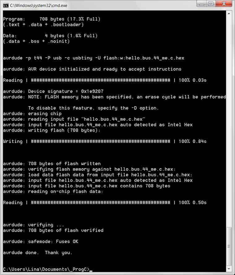
And I went on programming the bridge and the remaining board one by one with same code and changing just the node number
Not Error messages but not feed back to from the board!
Debugging_ starting from 1 board
1_Double check connections:
I found that RX and TX were directly connected instead of have across connection! I just invert the the pins attribution of in input and output from :
#define serial_direction DDRB
#define serial_pins PINB
#define serial_pin_in (1 ,, PB0)
#define serial_pin_out (1 ,, PB1)
to:
#define serial_pin_out (1 ,, PB0)
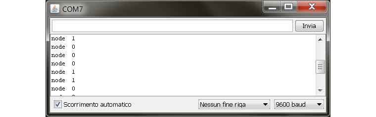
after that from the Arduino's IDE Serial monitor the board 0 was replying. But still not LED blinking
2_Check Output Devise:
I program the board adapting the Hello.RGB program to the attiny 44. And the RGB output device was fading trough the colors has well has with the attiny 45 board. That confirm at the same time the LED's connection and the .make file that is the same apart the name. Double checking the LED's pins attributions we (Ferdy and I) found that the Hello.RGB prog. even working has one wrong attribution: red LED was defined into PA7 instead of PA5...
3_Changing LED's attributions in an experimental way:
Once copied the Hello.RGB.44 program's LED's attribution into the the Hello.bus.44.c file setting the red led to blink as feedback we finally had a Blinking response. Called from the Serial monitor the board was responding with a GREEN LIGTH. After that y was trying changing to the other LED to obtain the right attribution from :
#define blue (1 ,, PA6)
to:
#define red (1 ,, PA4)
#define green (1 ,, PA6)
check the end of the page for the result
Next step will be program an I2C network from Arduino IDE to make the RGB interact with sensorlight.
I2C
Design and fabrication

Se you at programing week
dowload file:design files_C code files_