add an output device + program it to do something
+
#1_Designing a (attiny 45) Light.me board
IFor that week assignment instead to design a new board I choose to design a brake-out output board connected by the same ISP Header used to program the board. In that way I will have the possibility to improve the same output device in different board , with different micro contoller and compare potential and differences. At the same time I will be able to try to control the RGB LED out put device interacting with the lightsensor without LEDlight's direct influence.
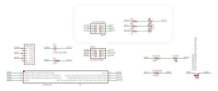
Basically the Sensor Board, with the micro controller and sensor, is the one developed in the input device week, corrected as explained in the week documentation. And the RGB.one board design re-use MISO MOSI and SCK connections that being fixed for each board, due to ISP programmer, and always analogical, are perfect to make the new break out board adaptable.
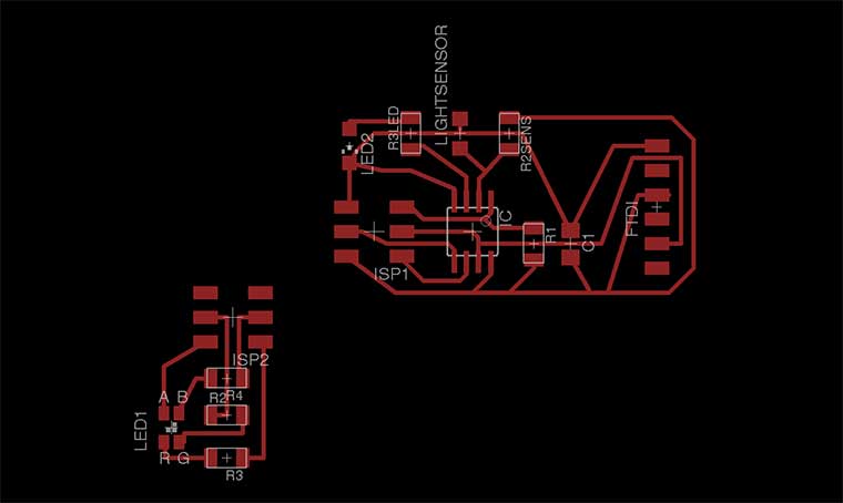
I milled it with Roland Modela MDX controlled by fab modules, as practice.
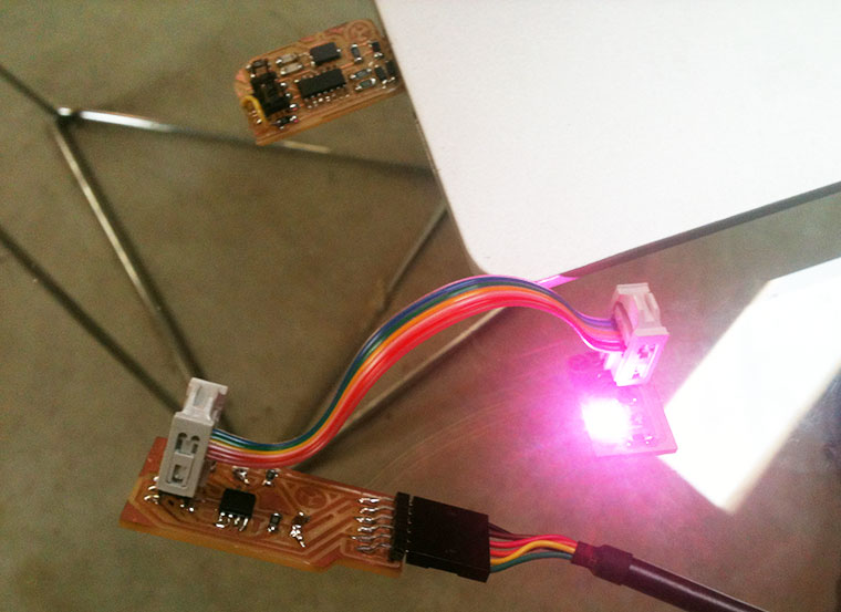
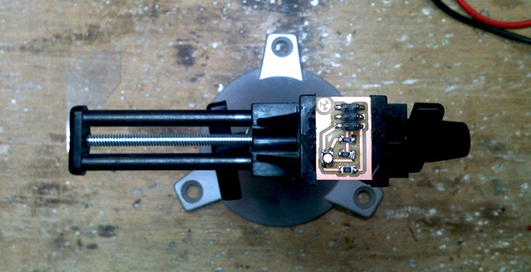
Than I solder the components , quite few this time having just one RGB LED (a really small one ) his 3 resistor, different for each led's colour, R2= 1K R3=1K and R4=499, and off course the ISP.
And than I tested it using Neil's C software. I flash it using from the Windows7 terminal.
C:\Users\Lina\Documents\_ProgC> make -f “hello.RGB.45.make” program-usbtiny
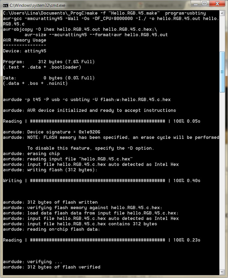
No errors...after that I disconnected the ISP cable from the USBTiny programmer and connected to the RGBone breakeout board. And that time was responding at the FIRST TIME!
dowload file:eagles files_ png files_
Next step will be program it from Arduino IDE to make the RGB interact with sensorlight.