Théo Lepage-Richer

Fab Academy / Digital Fabrication 2015

Eletronics Design; or, How I Ended Up Finding Electronics Surprisingly Meditative

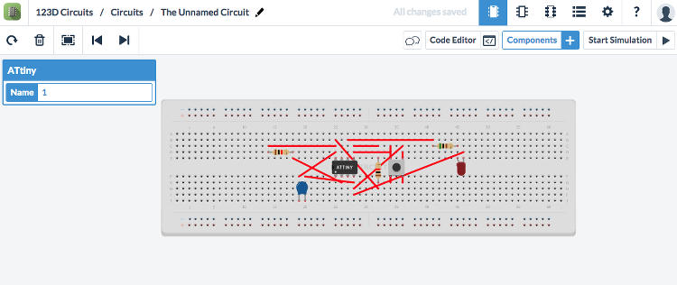
This week’s assignment consisted in redesigning Neil’s echo hello-world board by adding at least a button and a LED, and, to do so, I first installed the free version of EAGLE – a electronic design automation software. This program invites the user to first schematically establish the functional relations between his/her board’s components, to then translate them into a set of spatially movable pieces and paths. While navigating EAGLE’s dual, schematic/board interface can seem daring at the first glimpse, I found this program surprisingly intuitive and accessible as it seamlessly tackles the functional and spatial configuration of one’s soon-to-be board at the same time – that being said, I have to say that I would have probably not talked of this software in such positive terms if I hadn’t been introduced to it by these two very comprehensive tutorials on respectively EAGLE’S schematics interface and its printed circuit board layout.

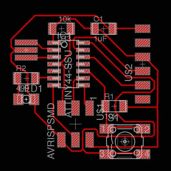
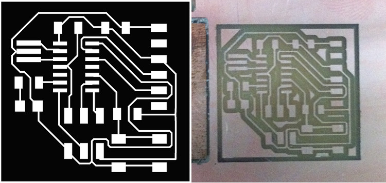
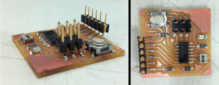
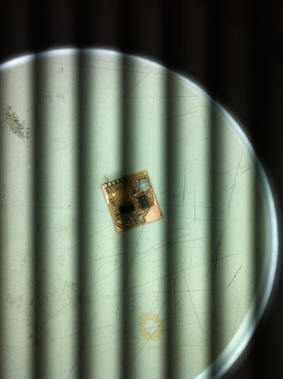
Personally, I decided to keep my board simple and stick to a single button and LED – without a deeper comprehension of the software capacities of such a piece, adding pieces seemed a bit premature, or unsounded, to me – but gave myself the objective to make it as small as possible. I spent a fair amount of time just juggling the pieces around to finally found a fairly efficient configuration by having an overarching ground line circling around the board. I then milled the board following the same steps as for week 04 and the final result took the form of a small square of with 30mm sides.

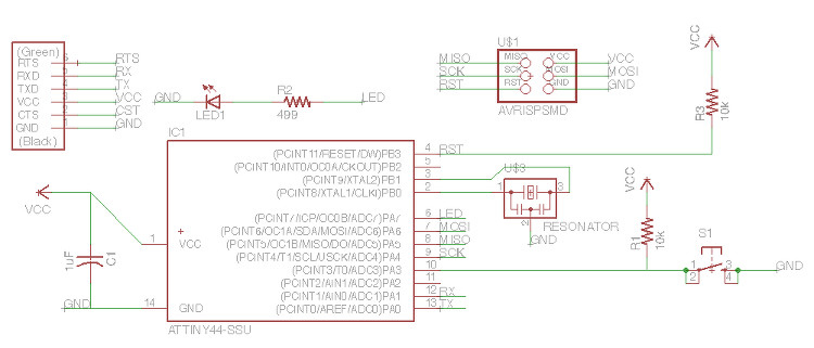
I then soldered all the necessary pieces, which go as follows:

  1. One CAP1206 capacitor
  2. Two 10k resistors
  3. One 499 Ohms resistor
  4. One Crystal Resonator
  5. One ATTINY44-SSU Microprocessor
  6. One button/switch
  7. One ARDUINO_SERIAL_PROGRAMSMD Pin
  8. AVRISPSMD Pin
  9. One LED

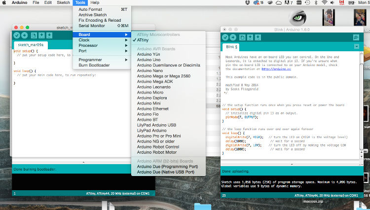
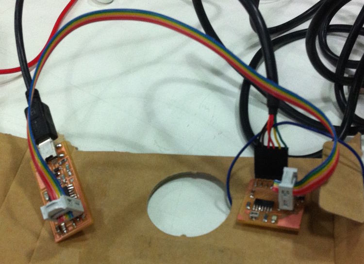
In the end, everything went well. The only major pickle I ran into was that I couldn't get the LED/diode to work, until I realized that I had soldered it in the wrong direction (the line is always closer to the cathode, the cathode is always connected to ground – I will never forget it). Using a voltmeter, I have been able to make sure that all the wanted connections were there, as well as confirm that – while having the board connected to my computer with a FTDI cable – that the expected 5 volts was indeed passing around. I then couldn’t resist taking some advance on next week and ran a simple Arduino test script designed to make the LED blink (very sophisticated, indeed), which worked without any problem – I am now looking forward to write my own script for my board!

See below for all the details/for each step.

Your Name

  • Week: 06
  • Subject: Electronics Design
  • Tools: Modela, Eagle, Arduino
  • Objective: Redraw/redesign the echo hello-world board, mill it and solder all the pieces
  • Files: Click here

Project 01a
As my experience in circuit design is absolutely inexistent, I was curious to give a try to the most visual design tool – 123D Circuits – but quickly found the exercise extremely annoying. Outside the obvious problems ensuing from unavailable pieces and the like, its both attractive and inefficient breadboard-like interface makes the whole process confusing as one quickly transforms the whole thing into a mess of tangled cables. Again, the same leitmotiv that I was confronted to since the beginning of the term was playing in my head – object-based software can indeed be more eye-catching and easier to grasp at a first glimpse, but the extra time necessary to tackle relation- or function-based programs pays off as they allow for a greater liberty of action very quickly in any design process.
Project 01a
The main advantage with EAGLE is that it invites the user right off the bat to establish all the relations that its board has to respect. I was a bit confused by all these lines running around my schematics, but realized that the whole thing could easily be cleaned up by labeling lines together (therefore, connecting them) rather than connecting them visually. My workflow was quite simple – putting all the pieces on the screen, building the little subgroups (LED/resistor, button/resistor, &c.) and then connecting them to the microprocessor. To calculate the number of ohms of the resistor connected to the LED, I used this little online calculator, which indicated that a resistance of at least 82 ohms was necessary to lighten (as opposed to burn) the LED. While I was initially tempted to use a 100 ohms resistor, I finally decided to use a 499 ohms resistor, as I could quickly picture myself burning my LED after few tries and spending ages wondering what went suddenly wrong with my board.
Project 01a
By switching to board view, EAGLE translates the aforementioned schematics into a set of movable pieces whose relations are visualized by small yellow lines. One can then move the pieces around and ask EAGLE to generate paths among them by hitting the Autorouter. While I ended up drawing most of the line, I found this automation part quite useful in visualizing obvious configurations and finding more optimal locations for some parts.
Project 01a
From there, I cleaned the board plan of all its layers except the obvious, red lines and exported it as an image. On GIMP, I could crop the unnecessary space and make a second file with a white line along the border that I later on used to cut the board on the Modela. For the actual milling, I followed the same steps as on week 04 (electronics production), but still had few problems with the milling board not being exactly flat – while a 0z milling would leave one corner untouched, it would draw a fairly deep line at the other opposite. To avoid breaking the mill, I therefore ran a first script at 0z followed by a second one at -0.1z. The result was satisfying and the board came out quite clean.
Project 01a
The soldering went quite well. The only problem was that I took the wrong part for the lateral 6-pin piece – I realized after having soldered this one that another one with bigger pins and on which the FDTI cable holds better existed, but I didn’t see the imperative to change it. It indeed proved to be tricky making the cable hold on to it later on, but nothing dramatic.
Project 01a
I then couldn’t quite resist the urge to make sure that my board actually worked. As mentioned above, I tested all my connections with a voltmeter and connected my board to my computer to see if the 5 volts was actually passing through. My only problem was when I directly connected the LED to VCC with a small cable and couldn’t light it up – the matter was simply that it was soldered in the wrong way (how very original). After this, I took some advance on next week and decided to install a simple Arduino script on it. I will indeed explain all this more in details in my next post, but let’s just say for now that I downloaded the ATtiny library for Arduino, copied it in my computer’s Arduino folder and selected the relevant settings in Arduino Tools menu.
Project 01a
I finally connected the board to my FabISP from week 04, used Arduino’s Burn Bootloader option to establish it as my board’s programmer, modified Arduino’s Blink script so it would match the ATtiny’s pin numbers (more information on this next week) and uploaded everything.
Project 01a
Et voilà! The whole thing might not be so sophisticated for now – and it will probably never be – but I was satisfied to have the confirmation that the whole thing was actually working… for now. Hardware-wise. Maybe. Let's not spoil it.