Théo Lepage-Richer

Fab Academy / Digital Fabrication 2015

Milling, soldering, and programming a board; or, the discreet charm of troubleshooting

This week’s project was probably is probably among the least ‘creative’ of the whole course – for we pretty much all have to do the same thing – but I was especially curious to get my head around electronics production by building a simple board à la Arduino (well, a fairly tone down version of it). Having worked before with Arduino boards and the like, I was already a bit familiar with programming electronic pieces yet had never tackled this work from an hardware perspective. I have in fact tended during my studies to stay closer to the ‘software studies’ part of computational architecture – engaging principally with the work of scholars like Luciana Parisi, Eugene Thacker, Wendy Chun and Alexander Galloway – but I now recognize that it is partly because my engagement with its hardware dimension has always been more limited. Maybe it is easier to make more radical claims like Friedrich Kittler’s “there is no software” if one has some basics in electronic engineering, who knows?

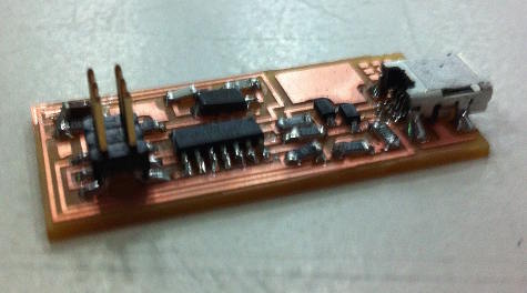
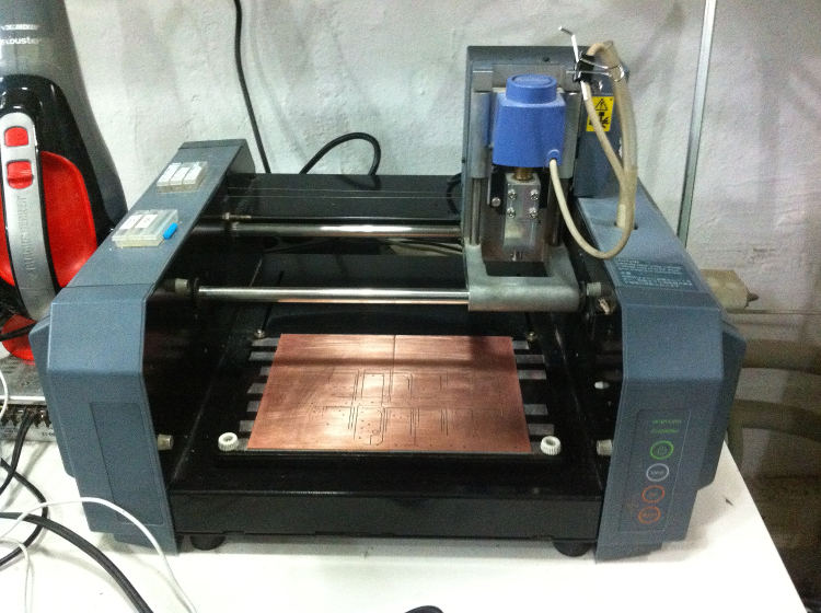
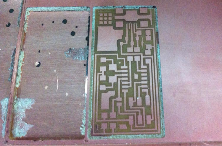
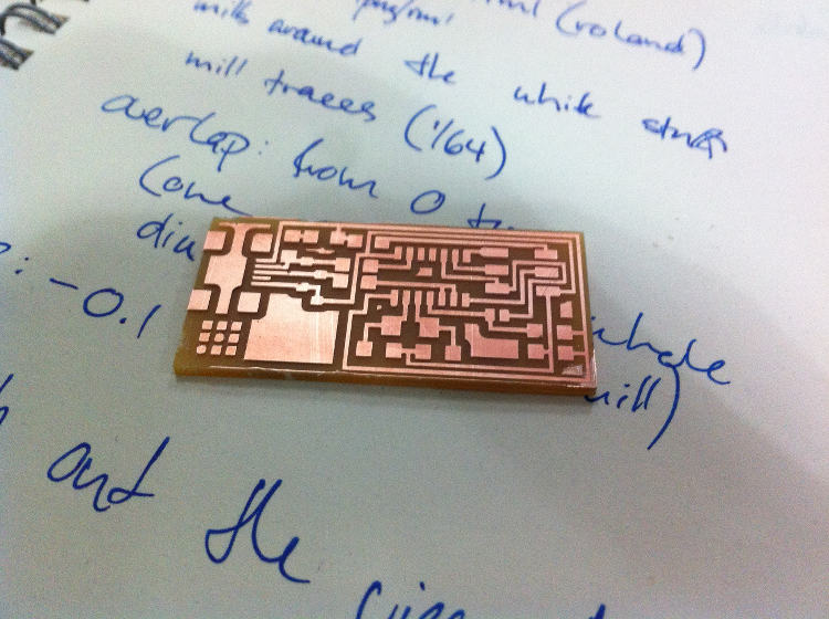
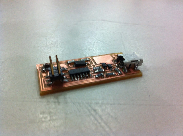
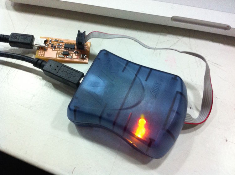
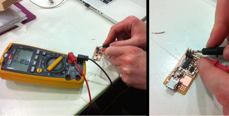
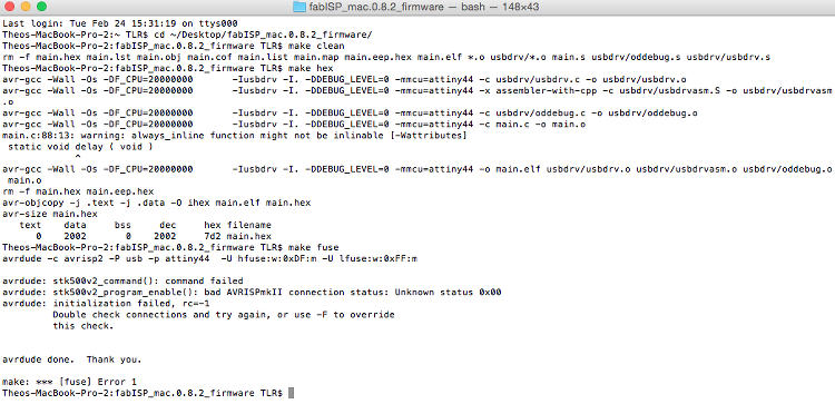
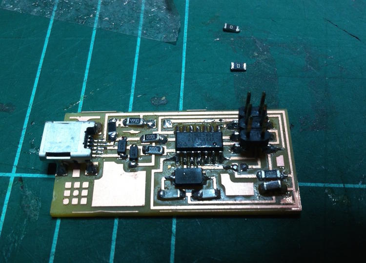
Anyway, back to basics (as I am still far from having developed the necessary digital fabrication skills to build upon these questions). We can divide this week’s exercise in three main parts – milling the board, soldering it and programming it – but my personal experience involved a fourth step that ended up being the most problematic and time-consuming one – troubleshooting. To begin with, we had the opportunity to decide among three different boards – Neil’s, Andy’s and Valentin’s – with all of them pretty much doing the same thing and sharing a common genealogy of one having influenced the development of the others and vice versa. I decided to do Neil’s as I thought that it would be easier to do the biggest of the three for a beginner like me, but it is the only one with a USB port, which happens to be the trickiest piece to solder.

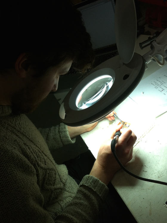
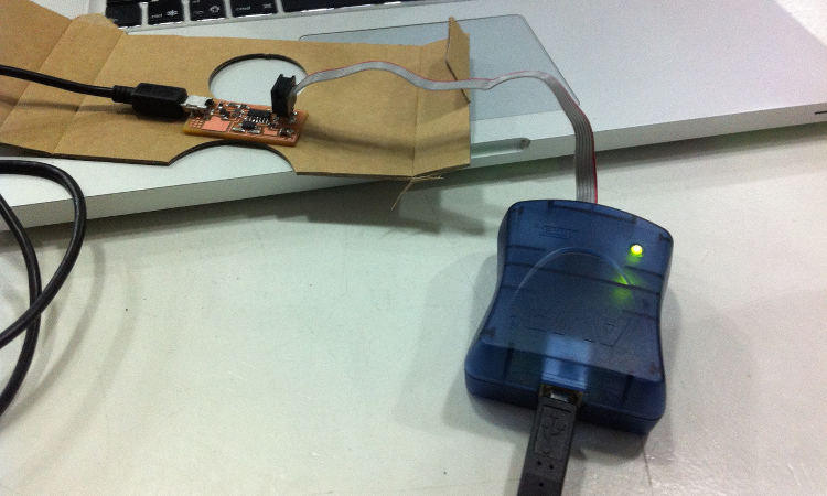
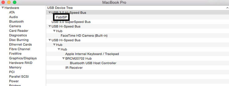
In the end, the milling part went well and the soldering surprisingly smoothly – and after two days of troubleshooting and Ferdi’s invaluable support (and patience) – I finally got the board to work properly. Please see below for all the details.

Your Name

  • Week: 04
  • Subject: Electronics Production
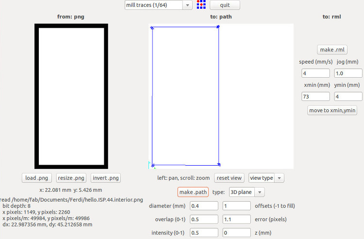
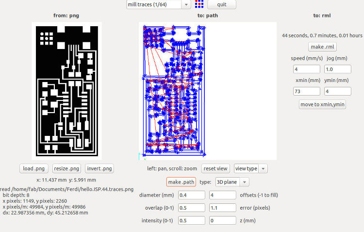
  • Tools: Fab Module, Milling Machine, Solder Iron, ATAVRISP2 programmer
  • Objective: Milling, soldering and programming one of the three FabISP models

Project 01a
The first step in setting up the mill – making sure that the board is straight – might seem easy, obvious or even dumb, but it is actually the most important part. To start with, one must make sure that the sacrificial board – the in-between layer between the machine main plate and the user’s soon-to-be-milled board is perfectly flat. To do so, it is imperative to flatten any mark with sandpaper, clean the surface with acetone or a similar product, and avoid as much as possible any hand contact. When this is done, the next step is to flatten the milling board itself – twisting it around a bit if necessary – and solidly glue it to the sacrificial board.
Project 01a
The next part involves sending instructions to the milling machine (a Roland MDX in my case). After having put the right drill into the machine (1/64 inch for engraving, 1/32 for cutting), I translated the .png plans of Neil’s FabISP into a .rml format by using the Fab Module. I set a new home point (x, y) on the software, but established the right height (the z axis) manually by lowering the drill until it just touches the board. To start with, I ran a ‘test run’ – a simple rectangle delimiting the size of the chip – to make sure that everything was alright. Yet, even though the z axis was set at zero – which means that the drill should have simply flew over the board – it engraved a line that was already deep enough for my needs, which means that the board itself wasn’t as flat as I thought it was.
Project 01b
In that sense, for the actual engraving, rather than setting the depth at -0.1mm, I simply left it at 0mm as with the test run, for this depth ended up being deep enough in relation to the orientation of my board. I then simply hit “make .path” and “make .rml”, and launched the engraving. .
Project 01b
The chip came out quite well. The bottom left part wasn’t perfectly milled as it was the lowest part, but it didn’t altered any connection, so I decided to keep it as it was. The last step of the milling part was subsequently to change the engraving drill for the cutting drill (1/32 inch) and changing the settings so the drill would do three runs around the chip with an increasing depth of -0.5mm at each turn.
Project 01b
The result was satisfying. This first part – the milling – went well, but I realized how much a single moment of vague laxity could actually render the board unusable and/or break the whole thing.
Project 01b
The second part – the soldering – ended up being both difficult and fairly enjoyable. This tutorial on the fab academy website gave me all the necessary information and good recommendations regarding the order in which the parts should be soldered. I indeed had soldered before – helping colleagues with putting together a bunch of quadrocopters on really short notice, despite my complete lack of experience in the matter – but never at such a small scale.
Project 01b
After two hours of concentration (and of mild headache because of the metal emanations), the whole board came together. I managed to solder most of the board by myself, but Ferdi had to help me out with cleaning the smallest connections, i.e. the USB’s and the microcontroller’s. As he refined these parts, he showed me how to de-solder clumsy connections – by applying a cable of copper and heating it up over the part to be cleared until the solder attaches itself to the cable.
Project 01b
It is then during the third step - the programming - that what had been so far a linear progression promptly stopped. When I connected it to my board, the programmer - the ATAVRISP2 - gave me a flashing yellow light (even though it seems red on the picture), which means, according to the aforementioned tutorial, that "the board is getting power, but most likely the 6-pin programming header is not soldered correctly".
Project 01b
It is at this point that the ‘real fun’ began. Ferdi thoroughly checked my board and couldn’t find any visible misconnection and therefore recommended me to review each connection with a voltmeter. I started by checking the connections that traversed the board as a whole (ground, voltage, plus, minus, &c.) but couldn’t find any problem. I then verify each connection individually, as well as made sure that each resistor stood for the right amount of ohm. Still unsuccessful, I finally borrowed a working board from a classmate as a comparison to spot faulty connections on mine. After a while, I realized that the GND and RST pins of my board’s header (see diagram) were connected while they shouldn’t, and therefore went on to find the source of this misconnection. As the source of the problem could only come from the header, the microcontroller and the 10K ohm resistor, I de-solder all of them to finally realize that a very small drop of solder under the resistor was wrongly connecting two lines. Elated of this discovery, I brought the whole board together again, made sure that the two pins weren't connected anymore, attached the board to the programmer and…
Project 01b
Green light! (Well, to be absolutely honest, the light was initially yellow when I first wrote these lines, but it suddenly turned green for some obscure reason, but, hey, it works now. Maybe).
Project 01b
Unfortunately, the program that we had to install on the board didn’t share my enthusiasm. Following the instructions of this tutorial on programming, I went through the “make clean” and “make hex” functions without any problem, but got stuck at the “make fuse” one as the programmer couldn’t establish the necessary connections throughout the board. At this point, I had probably got a bit careless (and vaguely tired of all this) and couldn’t find the misconnection problem, until Ferdi pointed out the (fairly self-evident) problem – one of the microcontroller’s pins was simply not soldered on the board. It wasn’t really visible to the naked eye, but I realized how dumb I had been when he was able to put the blade of a utility knife between the pin and the board. Oh well – I now know that, if the devil is in the detail, electronics is probably its field of predilection.
Project 01b
After having soldered the reluctant pin, I could then finished the programming flawlessly, which was then confirmed by my computer recognizing my board as a USB input.
Project 01b
The programming (and mostly troubleshooting) part being done, I could then de-solder/get rid of the two jumpers (i.e. the two 0 ohm resistors). Et voilà!