WEEK 10. INPUT DEVICES
WEEK 10. INPUT DEVICES
WEEK 10. INPUT DEVICES
There is someone there?

Presence control is useful in many situations:
- In cars, to detect whether someone is sitting and has not fastened
the seat belt.
- In counting the number of people who go through a door (shop, concert,
popular race, etc).
- Security areas Etc.
I will build a pressure sensor for this utilities.
Basic assignment: Starting from the Neil's step response board, I modified
it with Kokopelli to add in a feedback LED that blink whether it
is acting on the sensor.
Advanced assignment: Get the electrocardiogram with the Fab ECG, ADC and
substraction of the two signals, detect heart beat with threshold. (This
advanced assignment I did it in the stage 1 and 2 of my final project).
Content (linked):
Assignment:
TUTORIAL STEP RESPONSE PLUS LED.
Advanced assignment:
ECG from Fab ECG. (from final project)
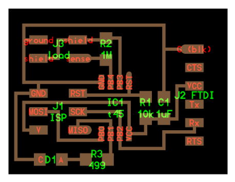
Starting with Neil's step response board (hello.load.45). Here is the
web side on Fab Academy:
http://academy.cba.mit.edu/classes/input_devices/index.html
The step response have two versions: loading and transmit-receive.
I have chosen loading version.
I have added a LED that give a quick feedback about how is working the
sensor. The board changes have been done using Kokopelli, but an old version
wich you can read and write .cad file straight away with no conversion
required.
Download retro fab modules with Kokopelli retro version
After downloaded, you have to:
Unzip the folder
Open the folder in terminal
make fab
cd bin
./kokopelli -r
Don't do "sudo make install" if you have the new fab modules version,
just use kokopelli.
Kokopelli is an open-source tool for computer-aided design and manufacturing (CAD/CAM). It uses Python as a hardware description language for solid models. A set of core libraries define common shapes and transforms, but users are free to extend their designs with their own definitions.
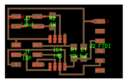
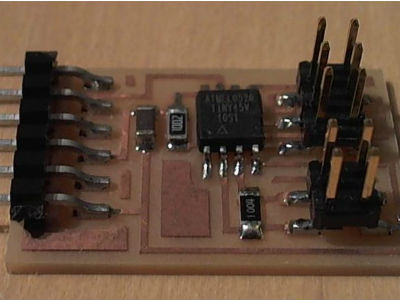
On Kokopelli, I have added a LED on Neil's board pin: PB1. Here it is
the new documentation:
hello.load.45.adolfo.cad
hello.load.45.all.adolfo.png
hello.load.45.border.adolfo.png
hello.load.45.traces.adolfo.png
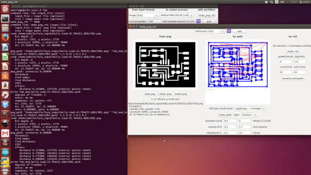
First, open the fab modules:
Open a terminal
tape: fab
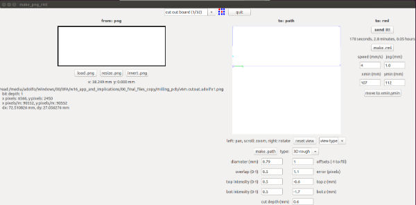
Second, choose Roland Modela:
Input format: image (.png)
Output: Roland MDX-20 mill (.rml)
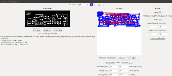
It will take 11,8 minutes to mill the traces.
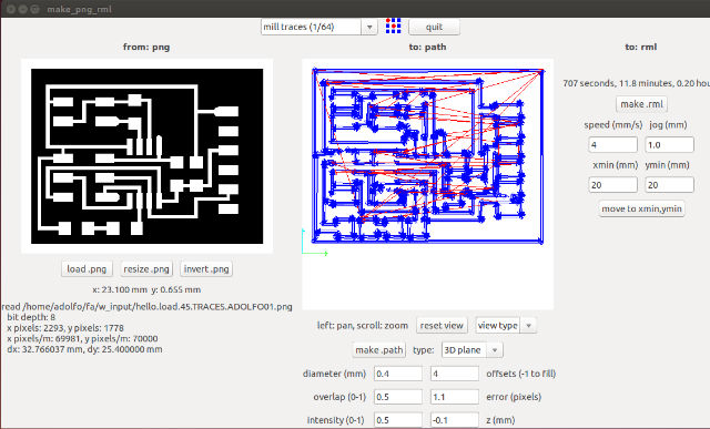
Settings:
mill traces: (1/64)
load.png: hello.load.45.traces.adolfo.png
offsets:4
make path
make.rml
send it!
Check: total size, zero point (move to xmin, ymin).
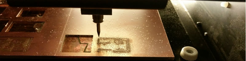
After little more than 10 minutes, milling traces is over.
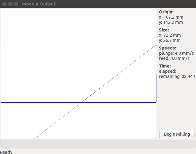
Then you just have to come back to step 4 and mill the border:
change the tool to: 1/32
load.png: hello.load.45.border.adolfo.png
use the same zero point (move to xmin, ymin) that was used on traces
Mill now the board border
On Arduino software, choose board and processor before burn it:
For Python installation I had many problems with Ubuntu (installing serial)
so I decided to do it in Windows. For installation I followed a tutorial
from fab academy.org in spanish "Ejemplos de dispositivos de entrada en
C". It was impossible to install Tkinter. Santi Fuentemilla (Fab Lab BCN
instructor), was trying to help me for 2 days.
Finally, I decided to focus my time to develop the input assignment
for my final project.
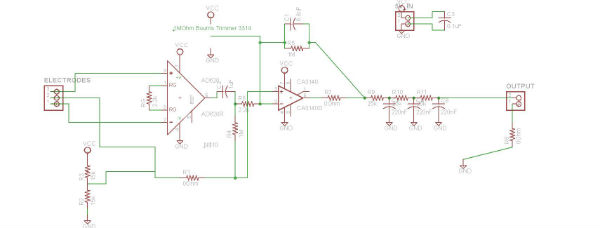
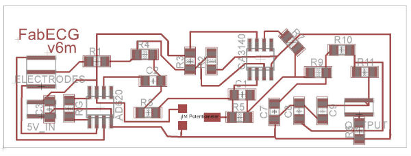
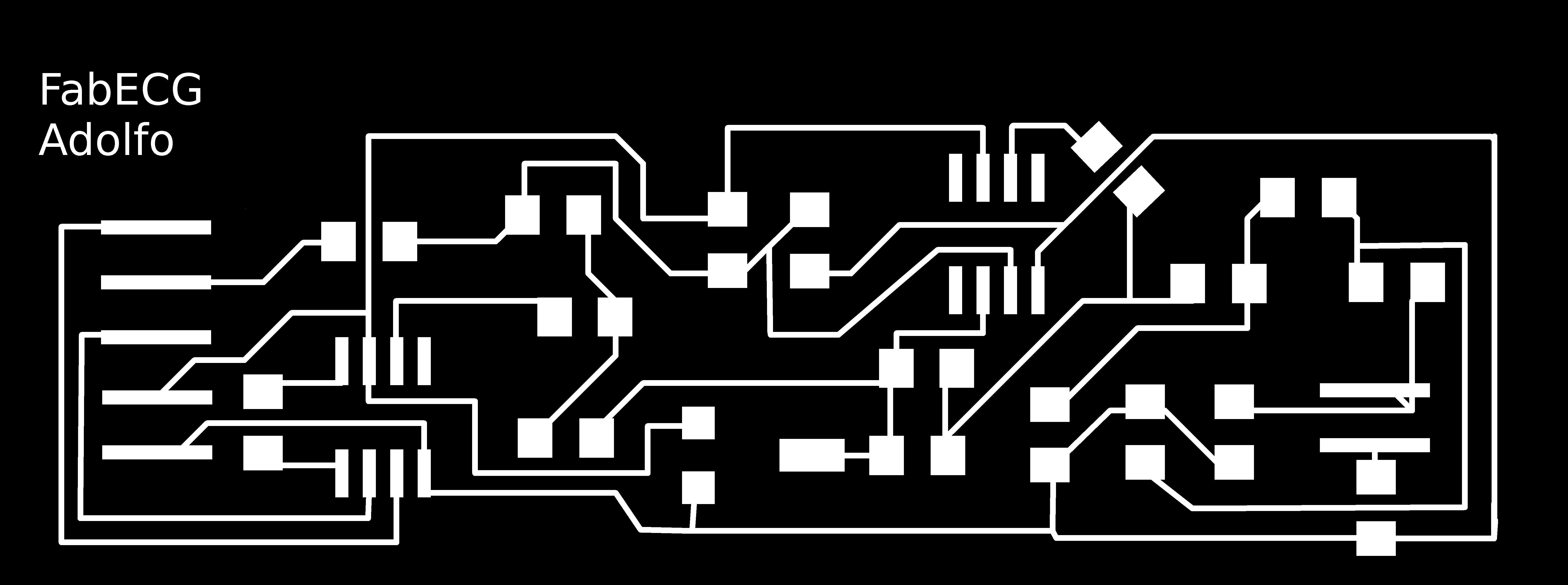
ECG from Fab ECG is a small part of my final project. It's the INPUT SIGNAL: Electrocardiogram, from my own chest. To place ourselves in the set of all the interactions and communications of my final project, I made a video of just over 5 minutes that makes a mountain view of the electronics.
Charles Fracchia and Adam Marblestone FabECG Week4 Fab Academy 2012
Charles Fracchia and Adam H Marblestone, have made an Open Source ECG
as a part of a collaborative effort between MIT and Harvard Medical School.
I have followed the tutorial of Adam Marblestone week5.
First I got all the documents:
Components List
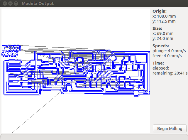
To see how to use Modela and Fab Modules, visit my
week4 Electronic production.
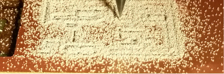
20mins 41 seconds for milling the PCB traces and less than 3 min to cut
out it.
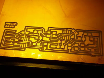
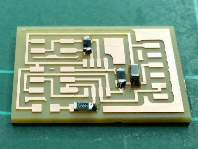
After milling, still in the modella.
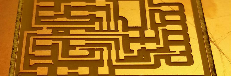
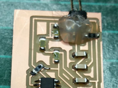
This is the second try, the first try there were many traces not
milled, probably because the board wasn't flat enough.
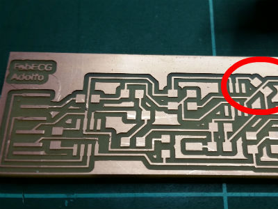
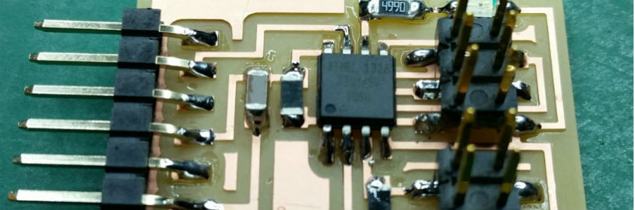
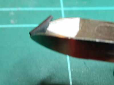
I checked all traces and I discovered two traces not well milled. It have
to be repaired with a cutter. Let's do it!
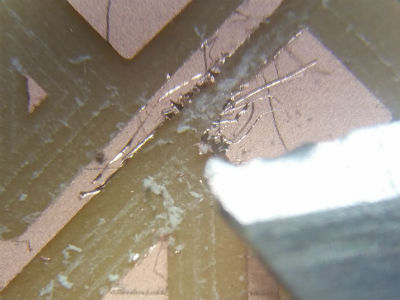
This is the microscope view after reparing the traces. It seems to be
ok, now.
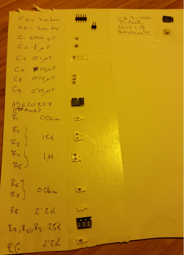
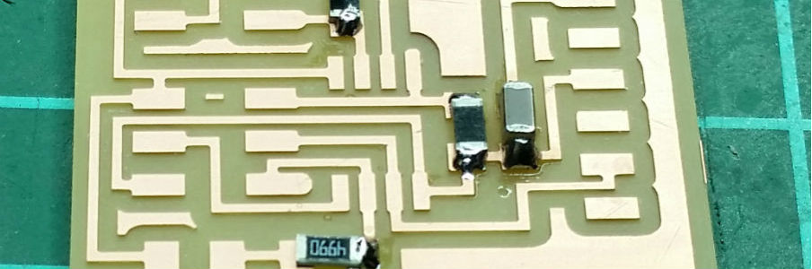
I'm used to make a list of all components in a piece of paper and with
double side tape, attach all components prior to start soldering.
This is a good trick from Ferdi (BCN Fab Lab at 2015)
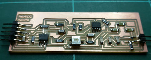
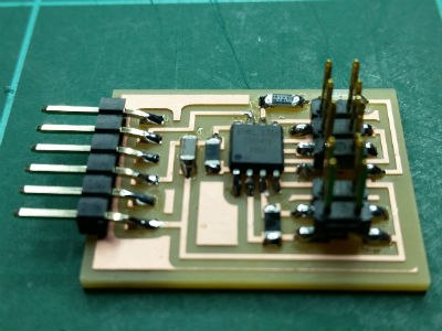
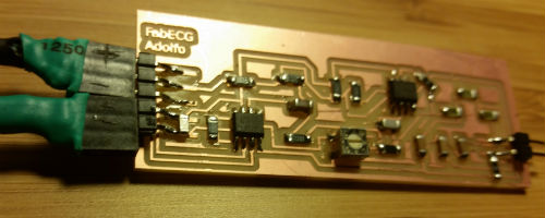
This is the final PCB soldered with all components on it. It looks nice...
There are many connections to do:
Clips for the electrodes (I will use commercial electrodes because according
to Neil, could be a nightmare project if I try to make my own electrodes.
ECG signal is 1mV signal, so any noise on electrodes will cover the signal.)
Cable electrodes to FabECG.
Connections to FabECG.
Battery case. I will supply with 5v battery case.
The Electrodes will need a female header for connect with FabECG
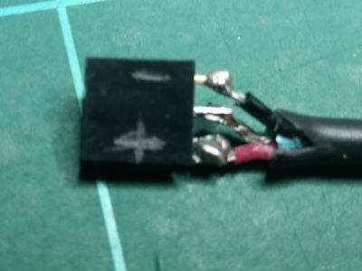
After solder the 3 pin connectios, seems to be too close to each others.
So I will cover the central pin to avoid short circuits
A little piece of plastic tube to cover the central connection
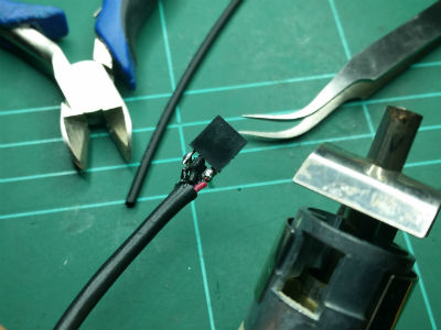
To make a protection for the central pin I have used:
Tools:
Plier
Hair dryer (electronics especific)
Tweezers
Material:
Plastic tube
I opened the plastic tube, cover the central pin, and finally hot air
from the hair dryer to adjust the plastic connector.
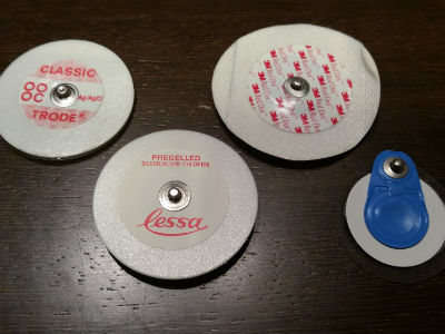
This is a commercial electrode for ECG. I got many of them from many different
brands.
All of them have a "clip" connection. So, next step is to make a clip
connection between electrodes and FabECG.
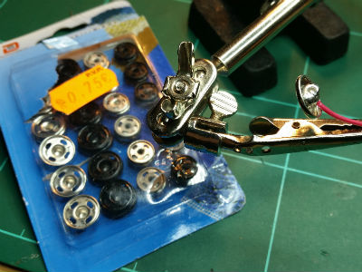
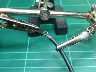
From a corner shop, I got some clothes clip and solder them to the electrodes
cable.
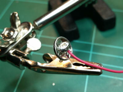
To adjust the clip to the electrode, a little piece of metal have to be
free in order to make the "clip" action. Many times, when I used tin to
solder, it solder this piece of metal, doing impossible to do the "clip"
action.
I had to make several attempts in each clip until welding wire firmly
and free clip.
FabECG connected to battery case cable and electrodes cable
After some test, the FabECG has need some reparations on headers. That's
because the FabECG it will be portable and those connections are not prepared
for movement.
Yes, I know... You don't need to say to me.
It's a shame!. It was very nice the FabECG before putting silicone,
but I need further testing without having to continually repairing.
It doesn't work yet... may be is the moisture of human sking under my t-shirt?? Mmm, may be.
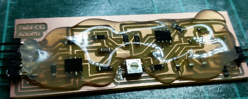
Yesssssssssss,... It's getting worse, isn't it?. Why that? Well,
I decided to destroy the nice image of my old "nice FabECG" because is
in continuous contact with human skin and may be this make some unwanted
connections. Hopefully, my final project will have a better case look.
Lol!
Adolfo is alive, it works!