
Claudia Aguilar
FAB ACADEMY 2015

MAKE SOMETHING BIG

For this weeks assignment we have to finally make something big, for this I've decided to make a step by step process so I can keep track of everything and make it as orderly as possible.
Next you can se the steps I took to make it.
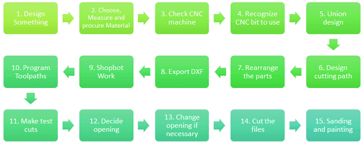
1. Design Something
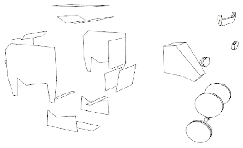
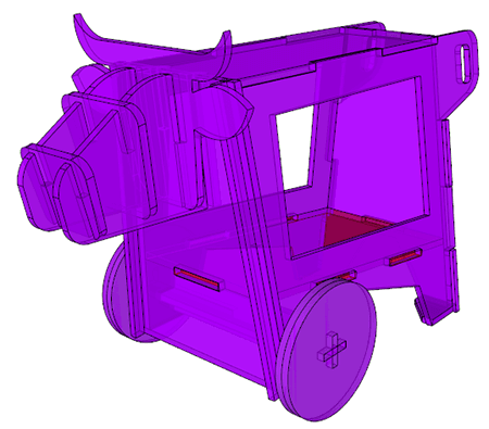
I’ve already had a volume design, but in this case I need to make the necessary changes and adaptations for this specific constructive technic: CNC cutting. What I’m going to do is take al the faces of the volume, extrude them with the exact material with and then follow the steps I’ve mentioned before.
2. Choose, measure and procure material
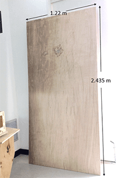
This time I’m working with Plywood a material that has an average of 10.82 mm wide so I’ll be working with a 11 dimension to calculate the joins of mi object. As you can see in the image the Plywood I had has one face pretty deteriorated from the dust in the laboratory and also it has stains which can be removed sanding it after cutting the pieces.
3. Check CNC
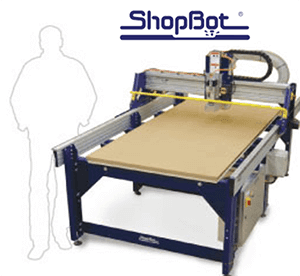
For this assignment I'm cutting off the pieces with a Shopbot.
What’s ShopBot? A ShopBot is a do-all tool for precisely cutting, carving, drilling or machining all kinds of things from all kinds of materials. With a ShopBot, you use the included software to design your parts on your personal computer, then, like a robot, the computer controls the cutter to precisely cut your parts. (source).
A Shopbot is a CNC Tool (for Computer Numeric Control).
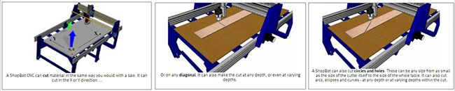
This kind of machine also allows you to create 3D shapes (See more here).
For more information about Shopbot, how to use it and others you can visit the ShopBot Wiki web.
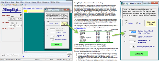
4. Recognize CNC Bit to use
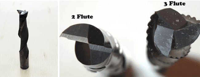
For the material I’m using (11mm Plywood), I’m using a 1/4” bit with two flutes. In the picture you can see an example of it, this is an example of a broken bit I found on the laboratory that is exactly the one I’m using.
This means that for the moment of generating the cutting file I have to take into account this diameter 1/4” or 6.35mm for the corners, unions and general parts at the moment of rearranging the parts for the cutting file.
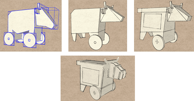
5. Union design (optimizing the initial design)
As I know how to use pretty well Sketchup, I decided to use it to generate the different parts of my object as it allows me to change the parts in a flexible way and also as fast as I can. This becomes only a pattern to follow for the next step: working the shapes on AutoCAD to procure everything is right and exactly for cutting. This is a disadvantage, if I know how to use a software as Rhino it would be easier, but I’m working on it.
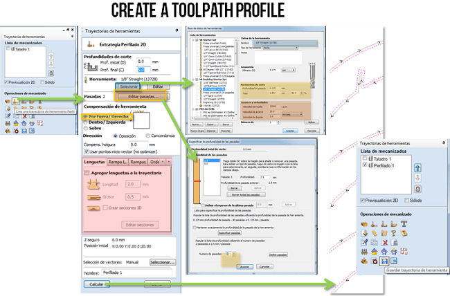
6. Design cutting path
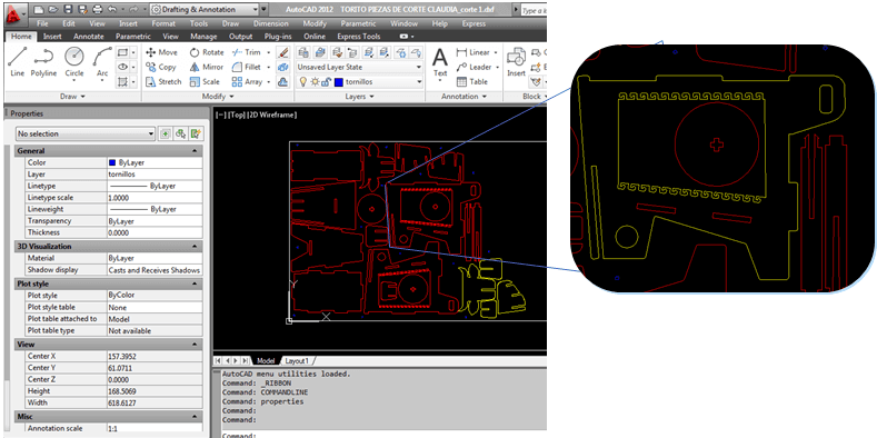
To design the cutting path I order the different pieces made in Sketchup and then exported in .dwg format so I can open it in AutoCAD. Once in AutoCAD I could check if everything is in order and if all the measures were fine and exact. I also took the time to make different details I couldn't do on Sketchup as it would take too much time unnecessarily. I also use Autocad to round the corners of all parts.
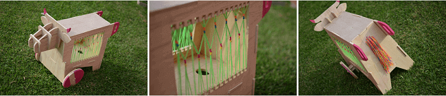
As you can see in the last image, I designed some oppenings to make a yarns woven design. To make it I calculate the oppenings depending on the size of the bit I'm using to cut.
7. Rearrange the parts
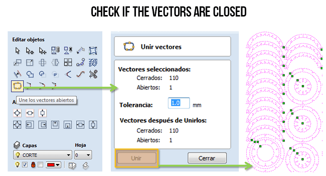
This is an important step as it makes you sure to use as well as posible al the material. In my case I had to check several times if the separation betweem the parts were sufficiently separated for the bit to pas.
You will see the importance of making this in the step 9 were you see the exact moment of the bit and you can check how some parts can't be cut off because of the small separations between the parts. To avoid this it's important to have it into account from the beginning.
8. Export DXF
This step depends uppon the program you are using, in my case working with AutoCAD and Sketchup I was already working with a .DXF file.
A DXF format comes from Drawing Interchange Format, or Drawing Exchange Format that is a CAD data file format developed by Autodesk for enabling data interoperability between AutoCAD and other programs. (Sourse)
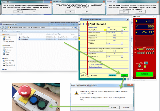
9. Shopbot Work
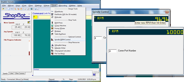
Next you can se the tools I used to generate the cutting Paths for the Shopbot.
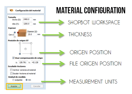
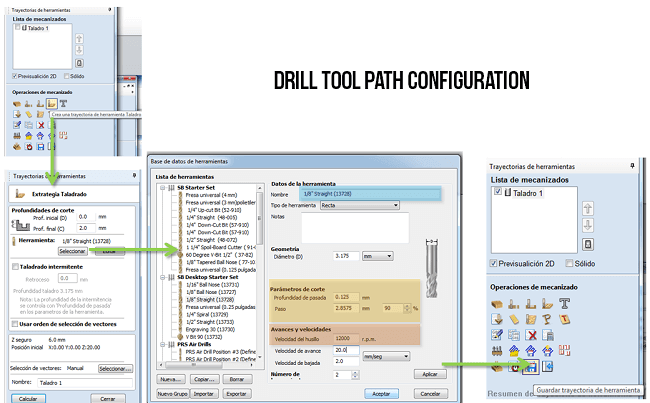
10. Program Toolpaths
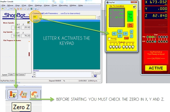
With the files ready it's just necesary to calibrate the Shopbot and then load the files and send start.
11. Make test cuts
For this I designed the same head I was using with the three test to see which was the best.
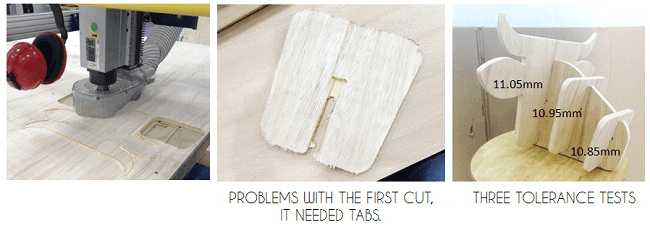
12. Deside opening
Making three test cuts I find out the best oppening for my pressfit. It was just necesary one more milimeter and it worked perfectly.
13. Change openning if necessary
Having tested I change the original design that was with 11.15 oppenings to the 10.95mm.
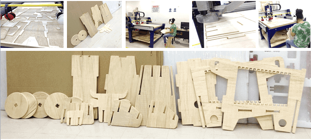
14. Cut the files
15. Sanding and painting
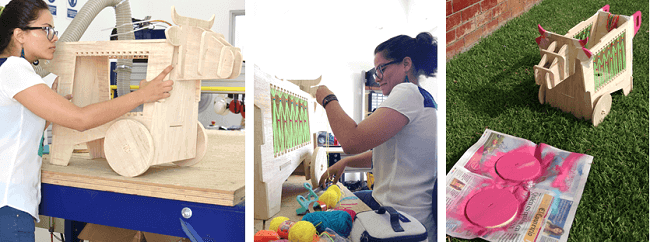
16. Show and share your Work!!!
You can download the 3D and cutting files in here.
Here are more pictures of the process of my Something Big:
Here you can see a complete video of all the machining and construction of the "Torito Pinto".
Before this experience I'd only worked once with CNC cut, with a custom, open-source CNC table designed by Ana Kaziunas France: the CNC Maker Bench. This was so useful and enriching for me because it is so clear and easy to make and helped me seeing everything as a process or with a clear methodology.
Click here to see this class content
Click here to see this class recorded video