This week’s assignment was very straightforward. Design the HelloFab board with a button and an LED light. Truth be told, I was not looking forward to this as the last boards I made (all three) did not turn out so well, meaning after many attempts to program, after changing out parts, after close inspection under a microscope, I was not successful. But, after a lesson on circuitry from Shawn (with input from Nadia) and reinforcement of Neil’s concepts, and following the tutorial word for word, I was finally able to get the hang of it.
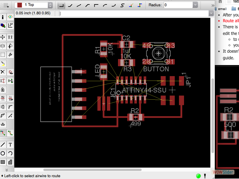
I really enjoyed working in Eagle! One of the great aspects of the program was to be able to check, by clicking and dragging, which components were actually connected. The electric test allowed for early error detections, of which I had some. Initially, I did not connect my lines to components properly, or give my resistors values, or name my parts. I called one power source VCC and one +5V which the program was not happy about, so I had to rename those values, changing them all to VCC.
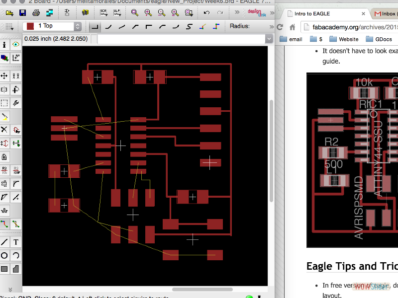
Some of the drawbacks were searching for the parts. Not all of the parts were in the Fab Board library, such as the 6 pin FTDI. The tutorials were really helpful in this regard, going back and forth between the libraries and images provided to make sure all the components were on the schematic. Making the traces was a fun process. After laying out my board a number of different ways and spending a few hours to try and not overlap any of the traces, I ended up going with the layout shown in the tutorial.
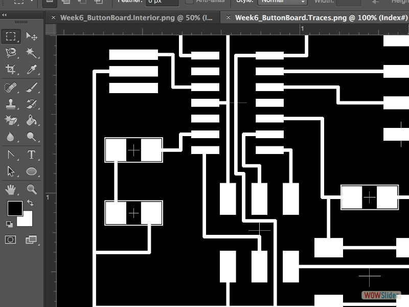
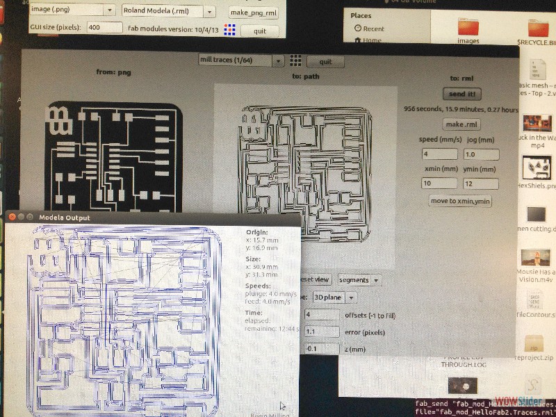
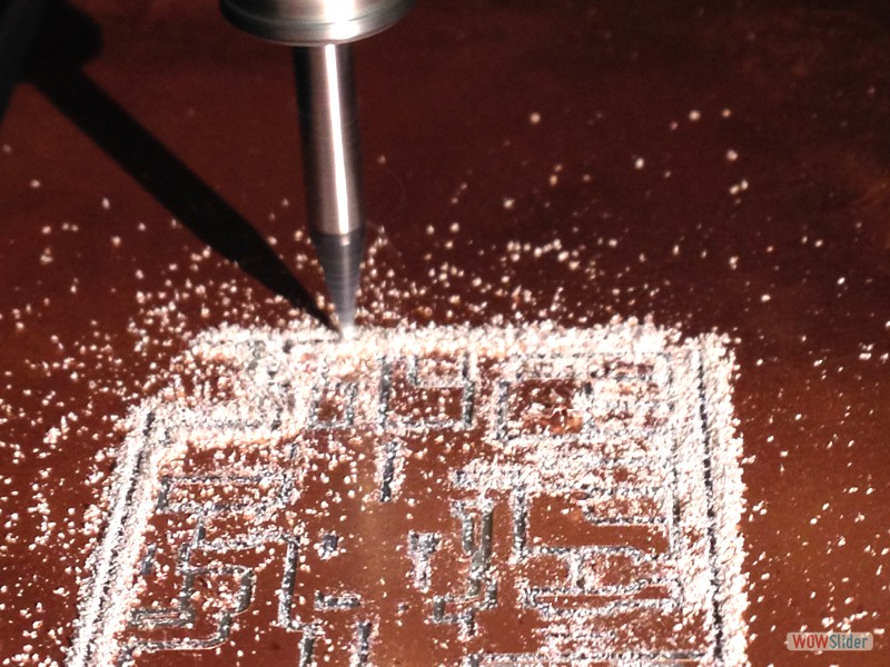
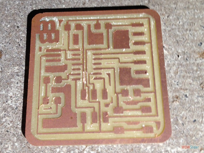
After exporting the board as a .png file, I used illustrator to crop the board, and add the border, leaving clearance for the FTDI. It did take a bit of time to build the correct files to export to the roland modela, as I tried creating a decorative, patterned boarder in illustrator which I sized wrong and had to let go of in oder to complete the work on time. Using the fab modules worked perfectly and the etching was completed seamlessly…no broken drill bits this time around.
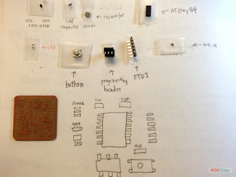
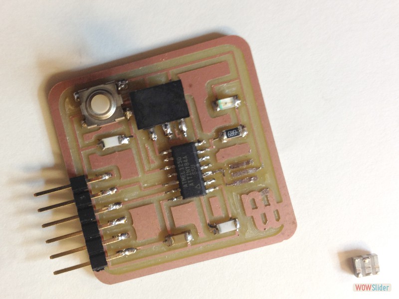
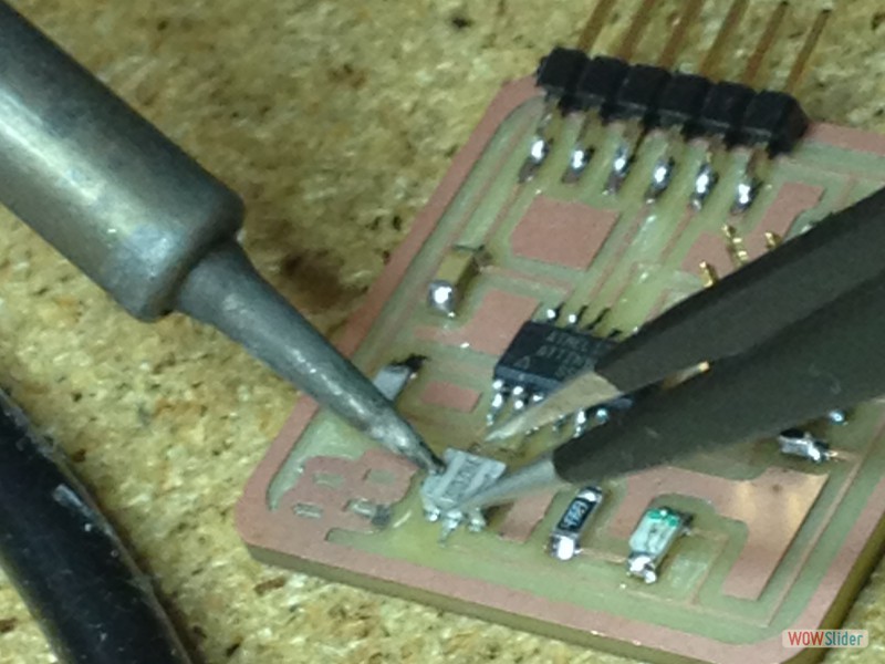
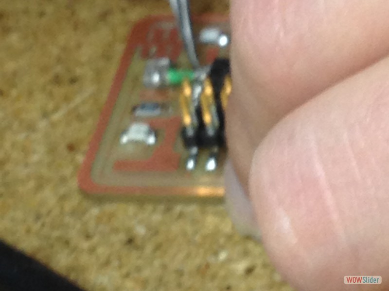
My soldering is also becoming more efficient. Instead of using the 499 resistor, I used a 49.9, which was suggested for a brighter light. I also found as I was soldering my 20MHz resonator that I had not properly milled the traces connecting it to pin 2 and 3 of the microcontroller. I left it off the board and proceeded without it, planning to use the internal 8MHz clock. After soldering, I went through the tutorial at highlowtech.org to get the Arduino software to recognize the ATtiny84. This all flowed very smoothly, without any of the installation glitches of some other program downloads, except that when Arduino created a folder in my document folder, there was no hardware folder automatically installed. This is where any additional board libraries are stored so that Arduino can access them. After creating the hardware folder myself, I was finally able to get to the ATtiny84 options in Arduino, access the clock options, and program the board.
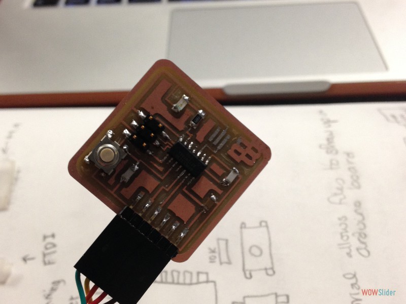
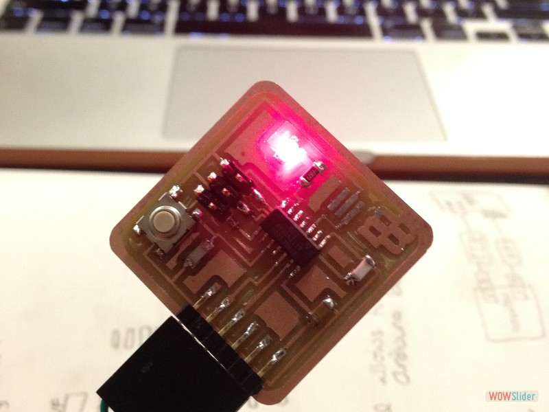
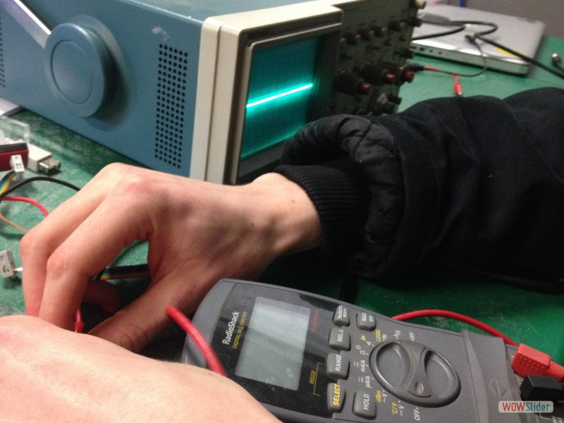
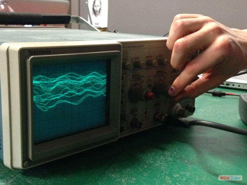
I ran the basic Blinking LED patch and the board did nothing. My board was still not recognized after switching all the FTDI, USB and 6-pin header cords to see if they were oriented properly, etc. Finally, the blinking light came on. The blinking was very slow though, about 2 seconds on, and 2 seconds off. Even when we sped it up to 1/10th of a second in the program, we were not able to get it to a quick blinking speed. Kenzo thought that perhaps it was the smaller power clock, so we added a jumper cable to make the 20MHz resonator connections. Yet even with the larger resonator, the blinking was still very slowed. Trouble-shooting led us to the multimeter where we checked connections between all the components, which were happily well-connected. That’s when Nadya brought out the oscilloscope. It was an instrument that had caught my attention because of the turquoise gridded screen that looked like it had been pulled from an old submarine, and I was very curious about its purpose. The oscilloscope gives a DC reading over time, versus the multimeter, which just checks for current. Yet, fun as it was to watch Nadya turn knobs and see the screen respond, we were still unable to find what was wrong with the board. Shawn suggested we try the ‘Burn Bootloader’ option in Arduino and the button came right on. Granted, it is a blinking light, but it was very exciting to have a working board.
After this, I tried the basic button patch. I was able to make the LED respond to pressing it, although it did not stay on or off. For next week, I would like to add another part to my board and create a program a little but more complicated.
relevant files:
 1
1 2
2 3
3 4
4 5
5 6
6 7
7 8
8 9
9 10
10 11
11 12
12 13
13 14
14 15
15 This work is based on the digital fabrication concepts taught through FabAcademy out of MIT at the AS220 campus