This page will contain a description of the process of creating my final project. I will begin by answering the questions set out for us in this weeks assignment.
What will it do?
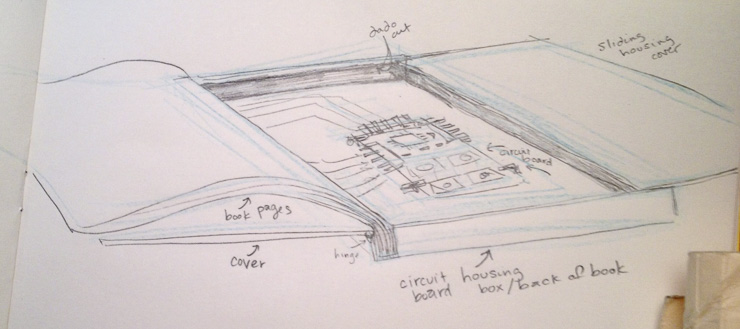
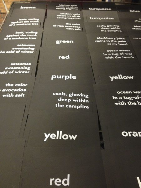
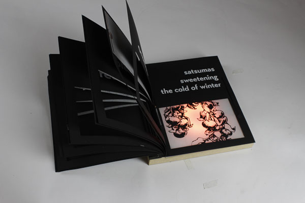
I have been very interested in works that use electronics in an analog way, modifying crafts and the traditional ways of interacting with objects in the crossover human-technological interface. My project is a children’s book that contains an embedded RGB LED matrix that changes color as the pages are turned, corresponding to the text on the page.Who's done what beforehand?
In researching, I found that there were a number of low-tech projects that incorporated electronics. I was inspired by folks who are focused on bridging the technological/digital and analog/craft divide. The following links are just a few: Because I was interested in making a children's book, I knew it may be necessary to use conductive ink instead of wires or copper traces. Additionally, because I wanted the circuits to be flexible on the paper pages, I also began looking into flexible circuitry. The following papers offer insight to all of these processes:Electrically Conductive Epoxy Adhesives
Pulp-Based Computing: A Framework for Building Computers Out of Paper
Research on Conductive Ink Market
Electronically Augmented Books
I did find some soft-circuit children's books that use a variety of technologies to power and signal microcontroller communication:Interactive Projection Mapped Books
The research also led me to the discovery of some very interesting electronic paper projects "out there." A few are linked below:surface switches and conductive paper
I also found many recipes online for conductive ink. Unfortunately, the best inks use silver particles or indium + gallium, which are very pricy so I found some that use graphite to test:What materials and components will be required?
The following materials will be needed for my final project. This will change as I figure out if I am going to use vinyl for the circuits on the page, phototransitors as circuit switches, matte board or wood for the book frame, and copper or graphite for the conductive ink.RGB LED – Digikey Part #CLV1A-FKB-CJ1M1F1BB7R4S3CT-ND $.60 x4
Phototransistor – Digikey Part #365-1481-1-ND $.38 x8
PCB FR1 – $.18
ATmega328 – Digikey #328P-AU-ND $1.92
Rocker switch – Digikey #EG4336TR-ND $3.50
Graphite Powdered Lubricant – Ace hardware $5.00
Poster Paint – $6.00
Smooth-On Crystal Clear Epoxy
Paper
Matte Board
UPDATED LIST:
Where will they come from?
Most of the pieces will come from Digikey, or the fab inventory. I will also have to go to local stores to buy some of the art supplies such as a rag paper for printing, a silkscreen, and the matte board.What parts and systems will be made?
I am working on making conductive ink out of graphite. I would much rather so this than buy the very expensive pre-made conductive inks. The physical aspects of the book, the housing cover for the LED, the circuit, the silkscreened pages and the book cover will all be made.What processes will be used?
Laser cutter for the book cover and electronics housing, programming in arduino, vinyl cutter for the flexible circuitry and silkscreen stencils, molding and casting for the RGB coverWhat questions need to be answered?
What recipe makes the best ink?
Do different brands of graphites conduct better than others? Copper better than graphite?
What is the best design for the spine to allow for the hinging, flexibility in turning pages, and rigidity for the electronics housing?
Is matte board or thin wood better?
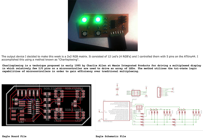
What is charliplexing for the LED 2x2?
What is the schedule?
May 20th: text written, inks tested, circuit mapped, 3D design for LED housing
May 27th: Book designed and storyboarded, LED housing made, Lasercut spine, Program written in arduino
June 3rd: Pages silkscreened, Lasercut adjustments for housing, Microcontroller programmed, book put together
June 10th: all adjustments made
UPDATE: this estimate was so far off! I was just able to get all parts working and coded for the 24th deadline!
I began the week by testing a few different ink recipes I found online. I tested these against a store-bought Bare Conductive ink that I had.
My materials:
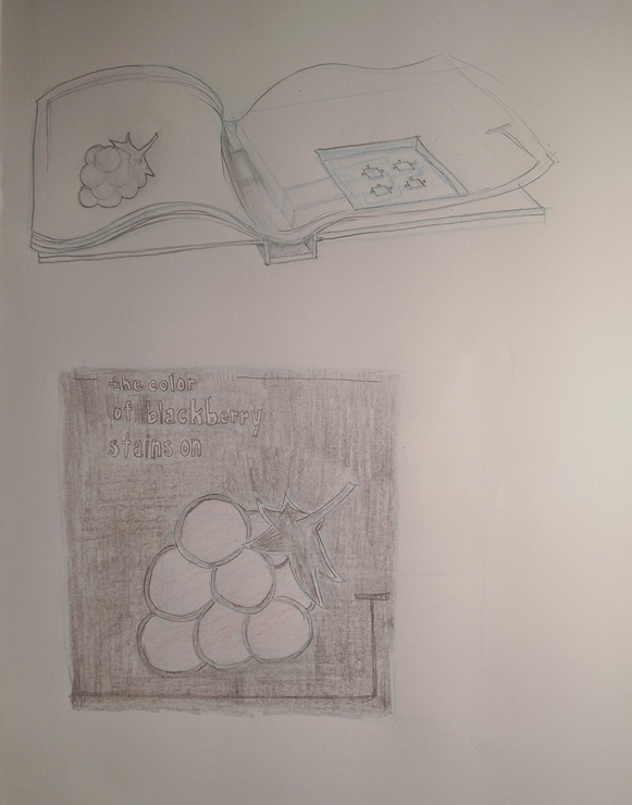
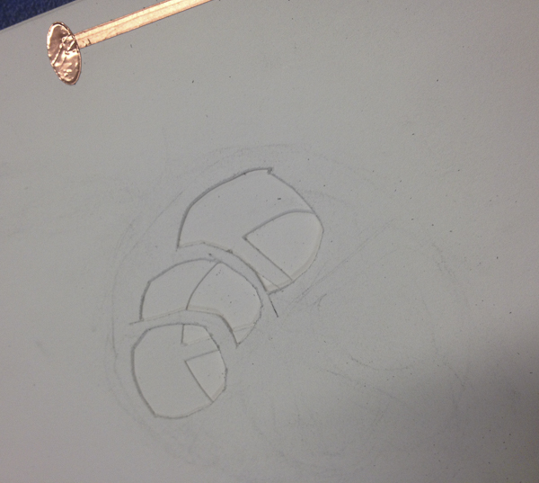
Some initial sketches
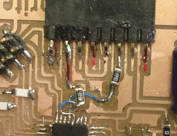
I also found this 2x2 RGB board from a past fab class which will be helpful in creating my RGB circuit.
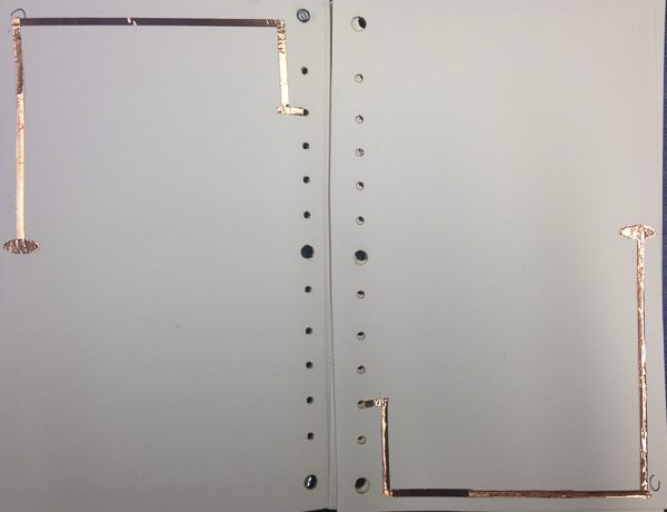
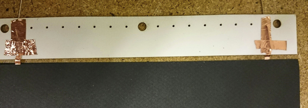
After all the work testing conductive ink, I found that the most reliable ink was still the store bought conductive ink because of the metallic nanoparticles in it. Rather that continue to experiment with the inks, I decided I would use the vinyl cutter to cut the copper circuits. Initially, the black ink was going to remain exposed on the outside of each page, yet a change in the design necessitated a 2ply page. This way, I could use the copper circuit on the inside of each page, attaching it to a spine and keeping it hidden.
a copper trace:
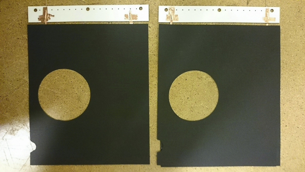
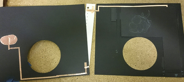
As I began thinking through the RGB LED, I had a number of challenges. Each page was designed to have a cut-away, and yet unless the cut-away was exactly the same for each page, each page would show the cut-out of the page below. In trying to resolve this, I thought threw scrolling books, a light table book, a turning wheel book, a box book, etc. Changing the design to more of a pop-up type interaction allowed me the flexibility I needed to show each page’s visual imagery without interference from the page below.
Initial brainstorming of book format:
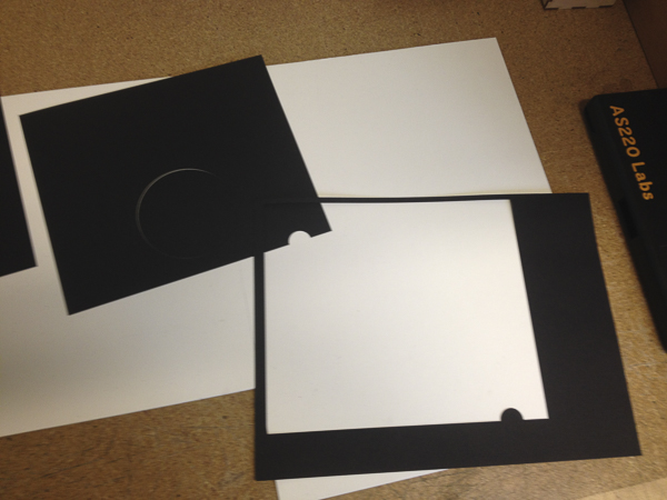
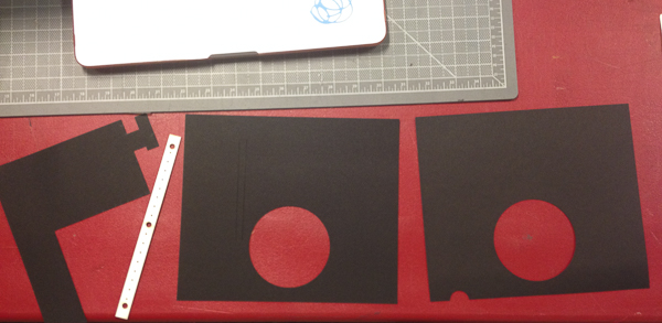
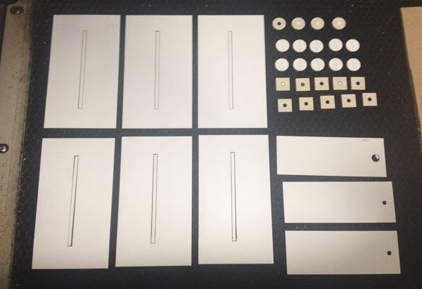
It was time to prototype the book pages with the laser cutter. I designed the pages in Inkscape and then assembled them by hand.
prototyping pages on the laser cutter:
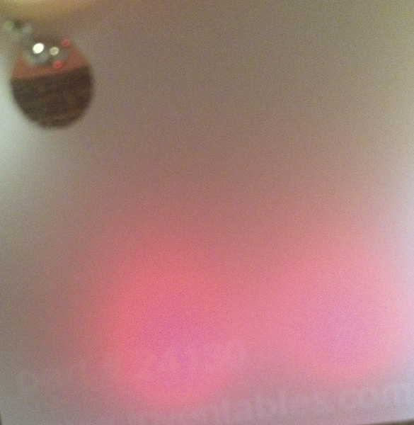
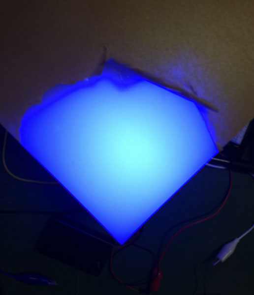
Another challenge will be how to diffuse the RGB light so that it is not a pinpoint of light but a soft glow. I decided to go with the Adafruit Neopixel WS2812 light ring because it has the integrated drivers and you only need one pin to control the whole ring. It uses 5VDC, or 4-7V, and works with the Arduino library. We had some different types of plastic from Instructibles in Lab which were helpful to try out.
testing diffusion of LED lights on different plastics and peeking inside a light table:
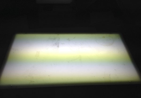
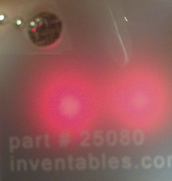
settling on a 40% Light Transmission Acrylic Sheet from Inventibles
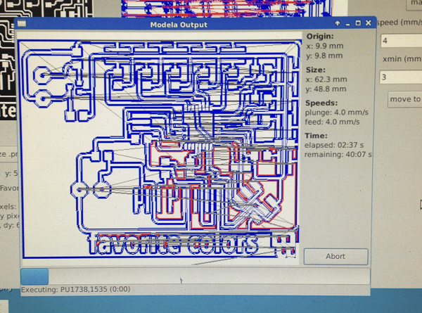
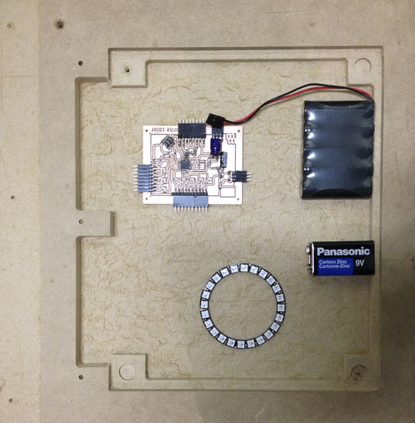
Then came milling the board with which to test the prototype. I was able to pull a lot from the use of the ATmega 328 from the network and communication week. Each page in the book is going to be a switch with a pull up resistor that can either be HIGH or LOW. If the pin for that page reads HIGH, nothing will happen. If the pin for that page reads LOW, that the “button is pressed” and that page will initiate the change of a specific color RGB combination.
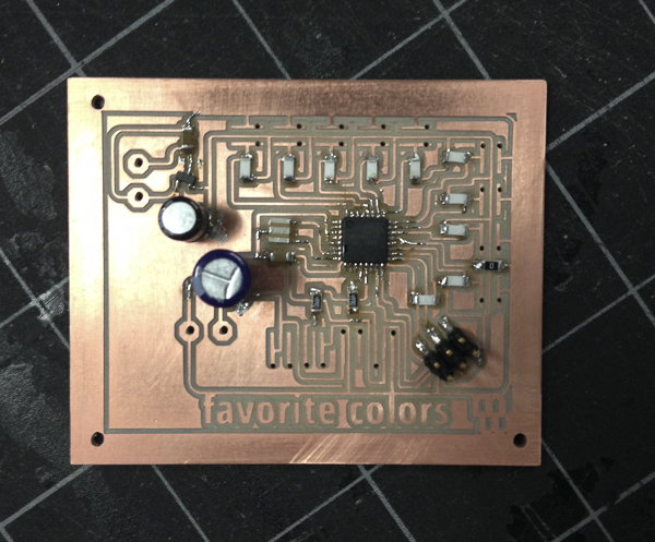
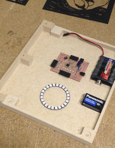
milling the favorite color book board:
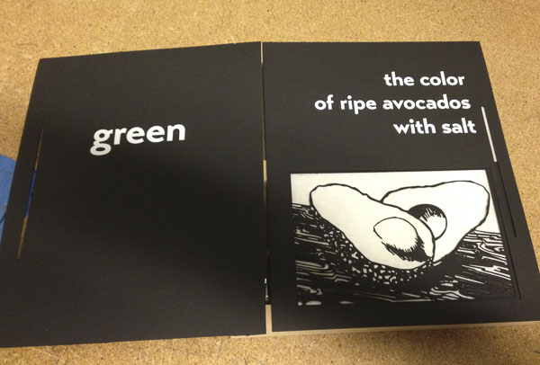
Beyond the mechanics of how the different parts would work together, I also had to consider the aesthetics. I wanted clean and simple silhouettes that would be backlit by the changing color of the Neopixels. My workflow was as follows: draw black and white images > scan and import jpgs into photoshop to alter contrast for pure black and white > export as pdfs to be read by inkscape> in inkscape, turn the .pdf into vectors > put on thumbdrive to print to laser printer from Corel Draw. Some of my inspiration came from the following woodblock and papercut artists:
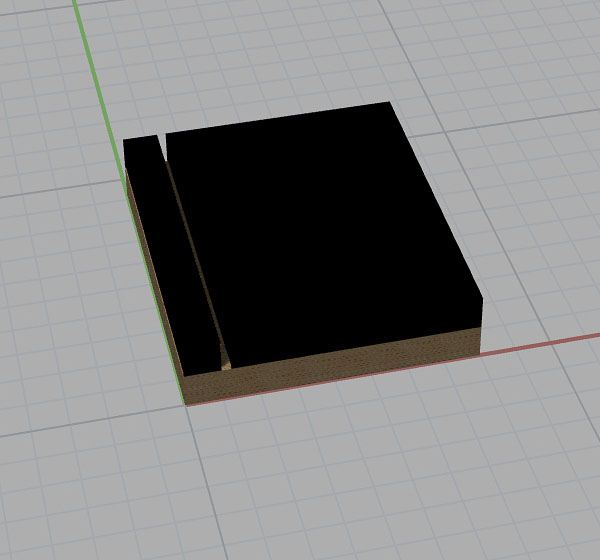
a rendering of the physical book in Rhino
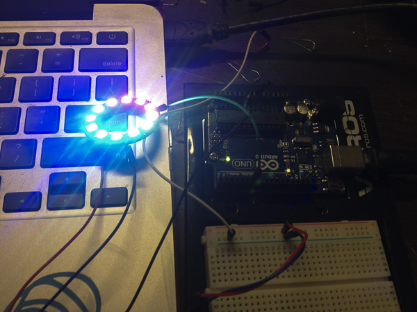
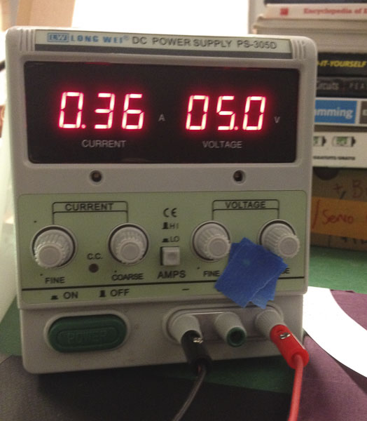
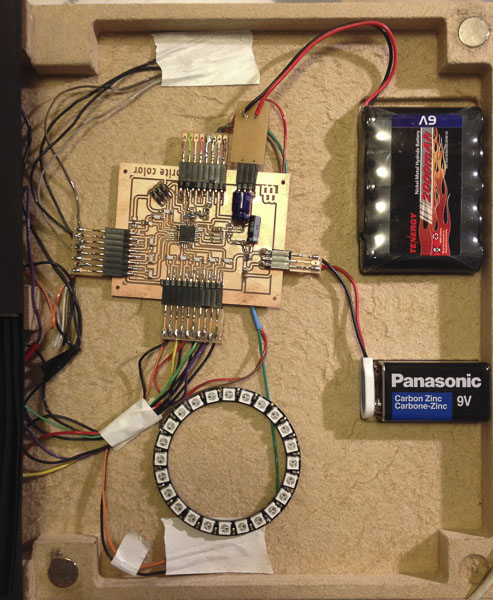
After designing my board, I had to test it to make sure it worked. I was able to burn the bootloader and upload to the board using Arduino. I was able to run the strandtest program for the Neopixel ring. I was also able to test completing the circuit with a page, but at that point, traces began pulling up from my pcb board.
reading the amp and voltage of the working Neopixel ring
One thing I continued to struggle with throughout the class was making the traces thin enough for the ATmega328 SMC pads but not so thin they easily came up. This continued to give me trouble throughout the project, even though I milled a second board, with somewhat thicker traces. Part of this was that in order to mill the individual traces to the pins, I changed the diameter of the pass to .25 versus the default .4. This worked fine for the traces but was too thin for parts that were undergoing any manipulation, such as the testing with alligator pins. I decided to use smaller PCBs which could clip into the main PCB so as to tug less at the connections. In order to do this, in my second design of the board, I changed the pads that were ground and pin input for each page to be horizontal instead of vertical on the 2nd board. This worked well yet I still ended up having trouble with the microcontroller traces.
troubleshooting the connections after pulling up really thin traces:
Not only did each electronic part need hours of testing, especially with the programming, but the art aspects did as well. Each insert was made of a laser cut silhouette mounted onto vellum. One challenging physical aspect was the sliding mechanism made out of paper that brought the insert into the light window. It did not end up sliding well causing complications in being able to complete the circuit easily. Additionally, I did not design the valley between the spine and the pages to be big enough so the pages would not turn well the further a user moved through the book.
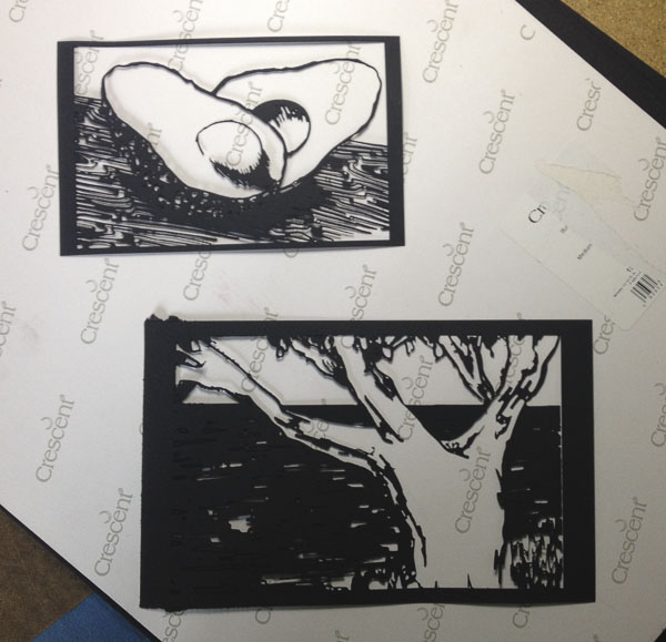
the inserts laser cut from drawings:
figuring out the sliding mechanism:
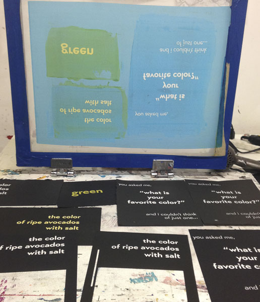
test print silkscreening:
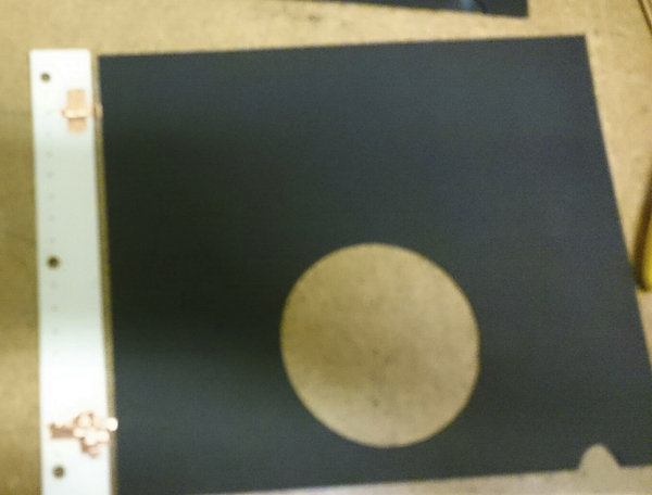
layout of the pages with insert down:
the book sandwich - paper, acrylic and mdf :
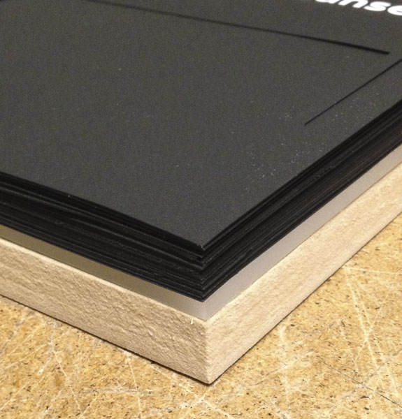
One of my favorite and most successful aspects of the design of this book was using the CNC machine to mill out 1” MDF board for the base of my book. This worked really well and I was able to create parts for the batteries and the wiring.
milling the bookbase on the ShopBot:
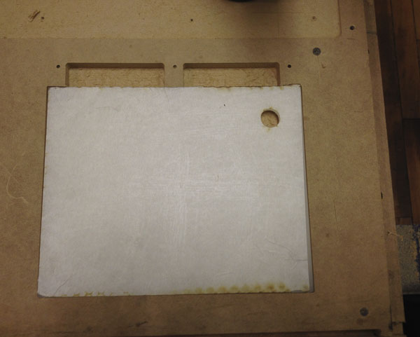
the bookbase:
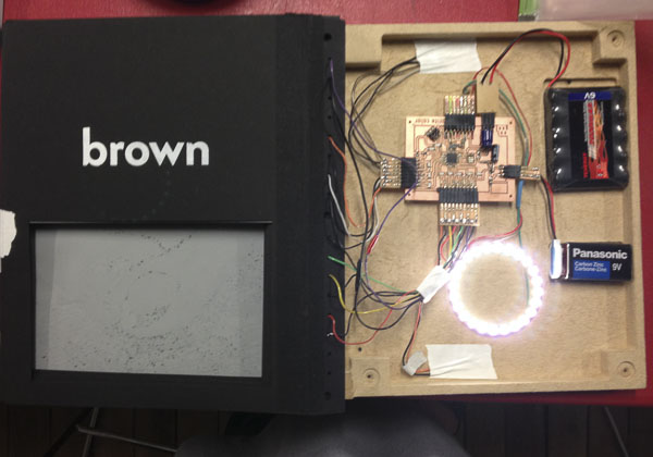
This ended up being a great way to experiment with the combination of art and making with electronics and programming. While I still have much to learn, it was a challenge to figure out how to integrate the different elements seamlessly.
pages turned to reveal electronics housing in back of book:
As I move forward with the design of this book, after the triage that resulted in this prototype, I am going to work on changing the following items:
and once that is all working, my final goal would be to have a window on the final page with a small screen. I would set up a web page in which people could pick a color from an RGB matrix and write a sentence as to why it is their favorite color. The final page would display that sentence on the screen and change the neopixel ring to also display the person’s chosen color. In that way, the book continuously updates and refreshes to be something new each time it is read.
relevant files:
- Final book board file
- Final book schematic
- Lasercutter file for book pages
- Lasercutter file for book spine
- Rhino file for book
- mdf base and electronic housing file for ShopBot
- Lasercutter file for acrylic light diffuser
- Example lasercut art file - blueberries
- Example lasercut art file - madrone
- Example lasercut art file - avocado
- Extra pads for securing wires
- InDesign file for graphics of book
- Arduino code test for one page
- Arduino final code (not an elegant function but a workaround)