The task this week is creating a board that talks to other boards, controlling the flow of communication so that nodes can act as transmitters or receivers. I was daunted by the week’s lecture as I still don’t feel that I have a solid grasp of C programming language. I have been mostly working off of Arduino sketches that are preset in the libraries or found in a beginner’s guide. I was ready to just mill Neal’s example boards of a bridge with 2 nodes, when we decided to go a different route as a class.
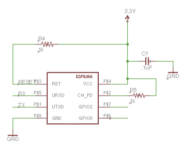
We decided that each one of us would be a node on a wireless bridge. We were hoping to create an interface based on color that will shift depending on who is communicating at the time. Shawn drew a schematic on the board that was very helpful to get us started.
The part we decided to use:
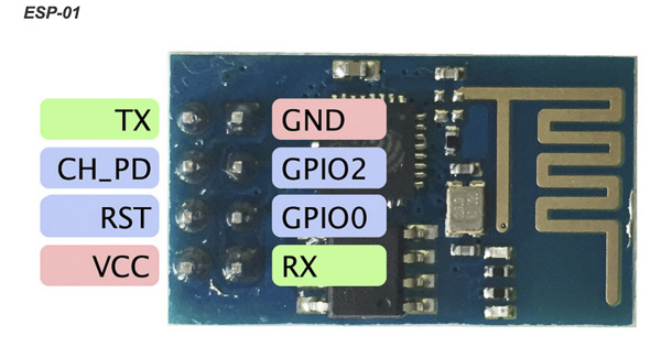
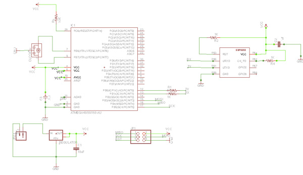
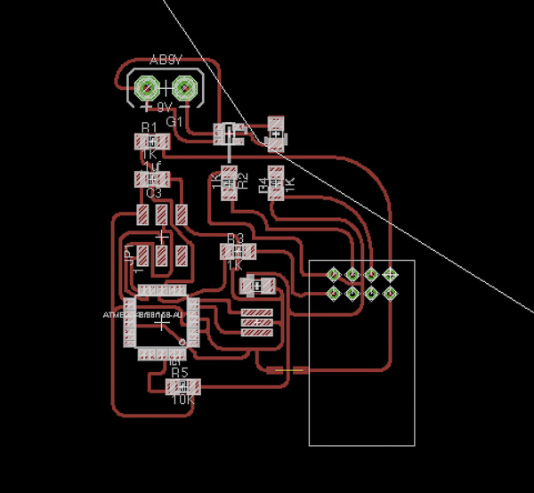
To begin with, we could not find our exact parts in the libraries. We ended up using the footprint for an ATmega48/88/168 instead of the ATmega328. Next, we had to locate the Modern Device library that had the ESP8266 library as none of us had it in our current libraries. This component was a through-hole component, which many of us decided to put on the bottom of our board. Because of it’s position, we had to mirror the part in the schematic before routing. Creating the traces was very straightforward although I had to set my grid to the lowest possible width in order to go through the component such as the microcontroller.
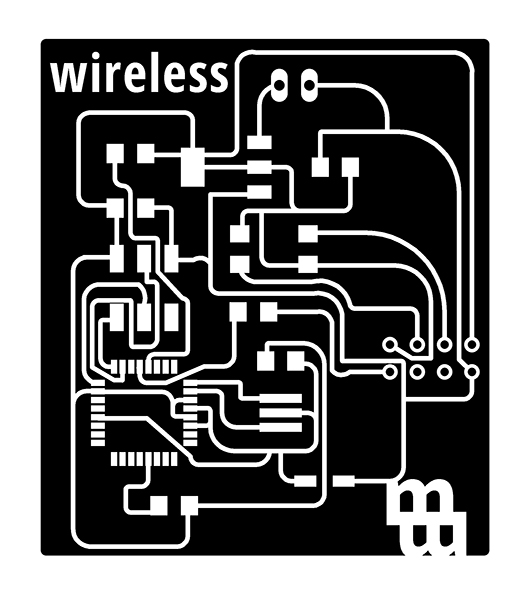
Getting the .png files ready:

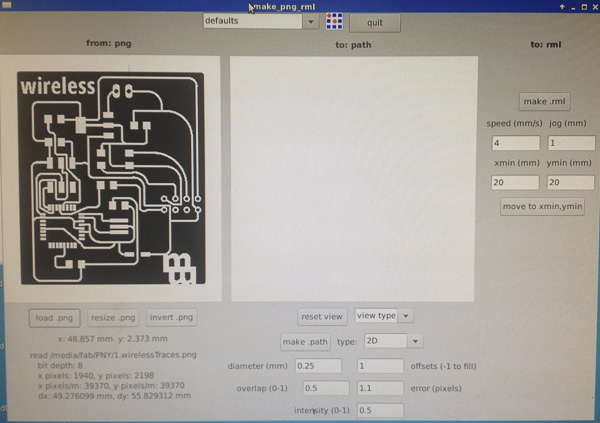
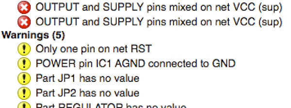
Working through eagle errors:

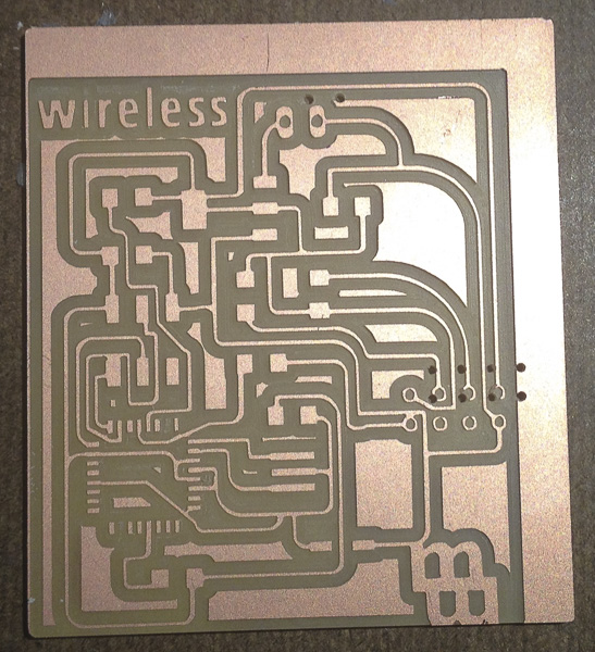
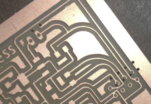
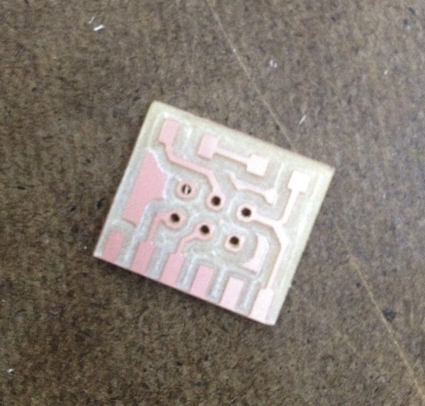
The first time I set up to mill the board, the 1/32” endmill did not cut through the tiny pads on my microcontroller and elsewhere. I set the tool diameter to .25 from .4. This worked out well and cut through the controller, but I must have shifted something from the traces.png to the interior.png. The through-holes were all shifted and the board not properly cut. I remade my files from the same photoshop document, with their canvas’ the same size. Then I remilled, remembering to set my endmill diameter as .25 and my board milled well.
The first board with shifted through-holes:
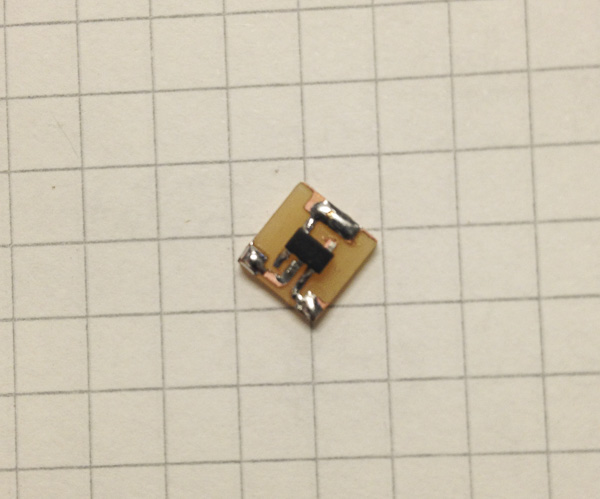
But that is when I found out that I was using the wrong regulator. This left my traces in the wrong spots, and I did not want to go back and remill. There was no simple workaround for this but Shawn was able to come up with a little hack that could be soldered to my board. I loved the concept of this little chip and it worked fine but it was very difficult to solder onto the board. Once that was on my board properly, I was ready to try and program it.
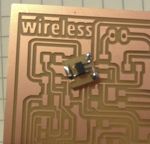
The board with the correct regulator:
Shawns regulator workaround:


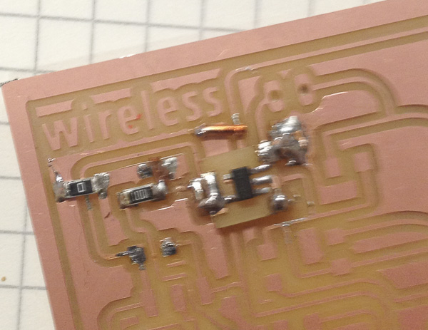
The now-known corrections to my schematic and board made in white lines:

All the components on the board:

The first few times I programmed my board I ran into several problems. Initially, the board continued to give me the same error receiving response. We decided it needed to be tested with a multi-meter, which demonstrated that I had three main mistakes. First of all, I accidentally connected my Tx with another pin, which needed rerouting and the cutting of a line of traces. Secondly, I did not hook up my Reset pins which Shawn helped me remedy with a little wire, and finally, one of the traces was too close to the other underneath the 6-pin header so I had to cut it. This is my worst-looking board to dater but rather than resolve it fully now, I have to focus on getting the board to work.
Initial Arduino errors:
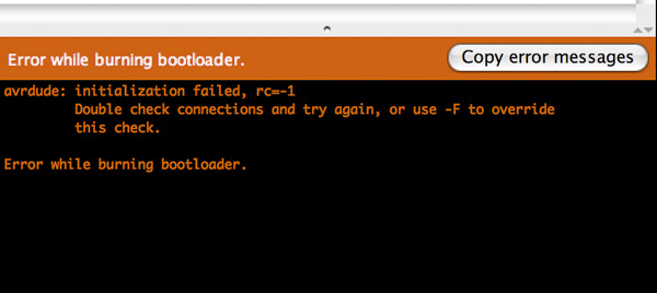
Next came the programming in Arduino. The first thing that was necessary was burning the bootloader. This went fine after the above fixes. Next was “uploading with the programmer” versus just programming with a USBtiny. Around this time, we realized there was no way of knowing if our boards were programmable unless we had some soft of indicator light. This is where Shawn came in with another hack. He helped us create a very simple blinking light LED that should demonstrate if the board was able to be programmed or not.
upload using programmer

We were not yet able to see if there were any errors or indicators when programming. I had cleared all my errors in Arduino and Shawn suggested I make one of the adaptors with the signal LED. The hope was that as people in class finished their boards, we would be able to test the node capabilities with multiple people operating on a wireless network. Sadly, we were not able to get this far. The board did not work for all but one of my peers. Because of the pace of Fab academy, we never fully realized our vision.
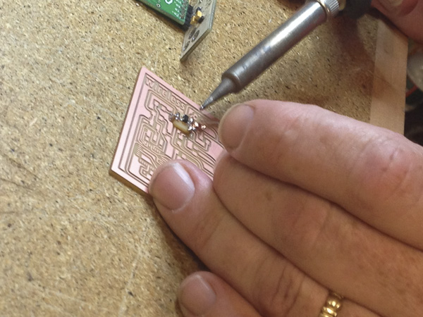
The LED signal attachment:
Successful uploading:

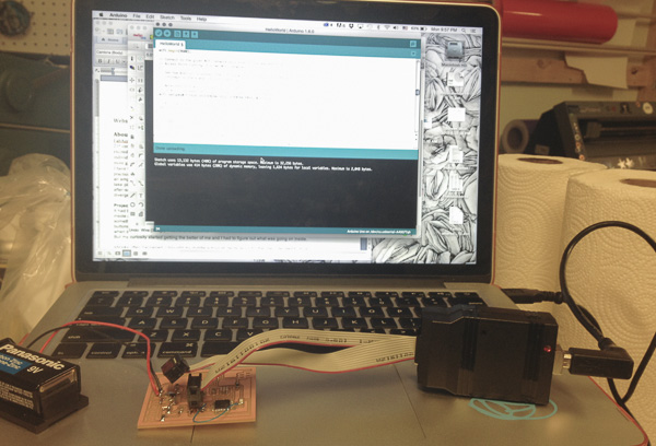
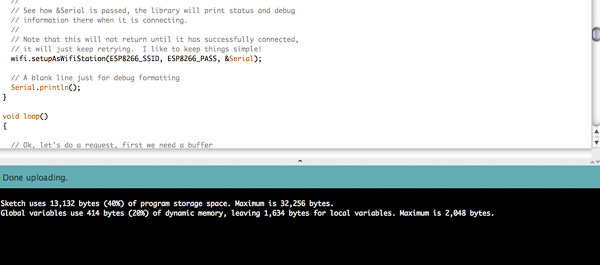
In subsequent attempts to make this a successful project I re-milled my board. I had some more greater success but was still not able to communicate with others in class.
A second board with an LED indicator:
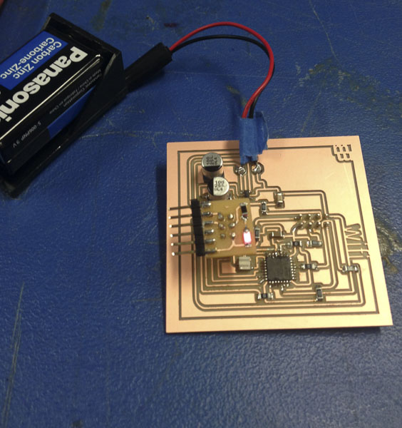
The wi-fi light is on indicating successful electroncis:

Programming with no errors but not the correct message:

relevant files: