I thought that this would be a great week to test yet another idea for my final project. I am very curious about embedded circuits in paper. After some thought, I decided to try an embedded circuit in burlap, experiment with the epoxy and thickness of layering. It may have been the influence of lots of rain, but I decided to undertake making bicycle fenders for this week, and embed LEDs along the ridge.
I looked at many different bike fenders online, from ones cut from detergent bottles, to inlaid wooden ones, fixed for a handmade bike. I chose a narrow fender for my road bike, which I will attach with 3D printed parts, once I see if the composite is successful. I will be able to use the same foam mold for the front and back fender, just making the front fender slightly smaller.
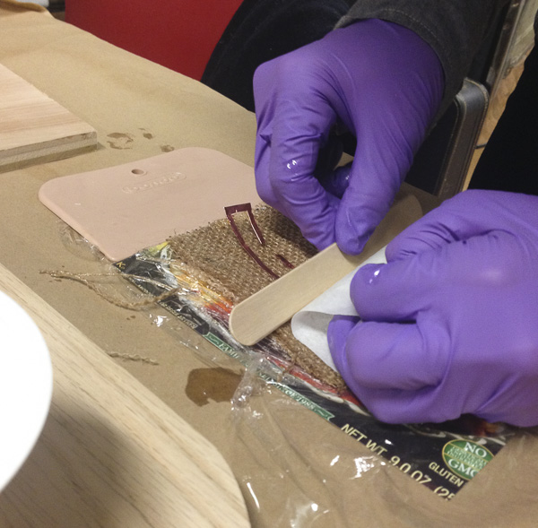
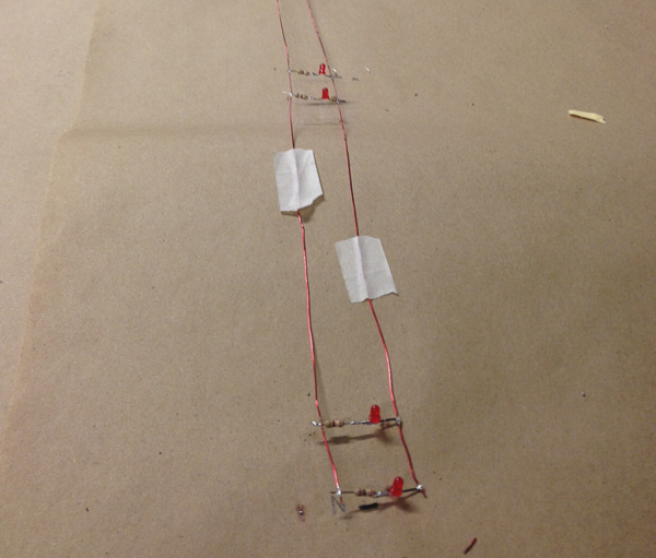
I began by making the tests. First, I tried using copper traces, cut on the vinyl cutter. I tried laying them into one of the layers and solder while on the layer, only to realize the whole thing was way to wet and messy to make that work. I gently set the LEDs and resistor on top of the traces without soldering and put the next layer on top, hoping they remained in place. At this point, I was pretty sure it was not going to work. But it would make a good test of the composite regardless so I continued with the process with 3 layers. I then sandwiched this first test square between two pieces of wood, and clamped it all together
Trying out the flat, embedded copper circuit:

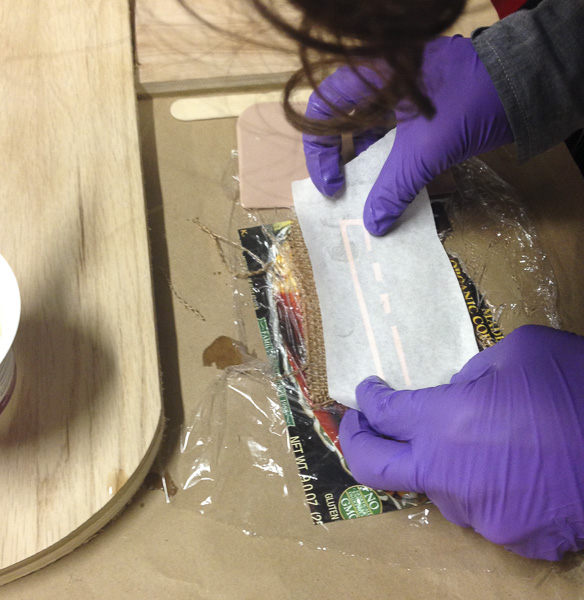
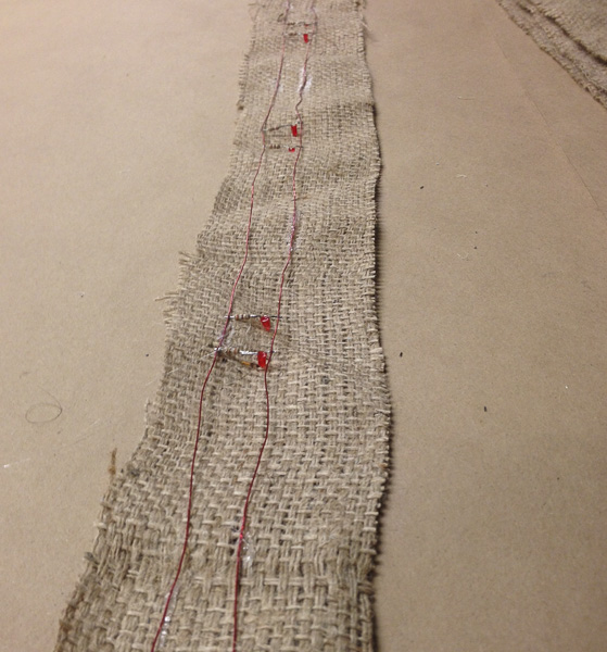
As I expected, the LEDs did not work, but I had already set to work on my second test. This time, I soldered the entire circuit ahead of time, and then on the third layer, I pushed it face-down into the burlap, and layered two more pieces on top. I followed a similar clamping technique, making sure to put the plastic wrap around the piece first. Lots of epoxy dripped out as it dried. This piece did manage to carry voltage and the LEDs lit up.
A working test for embedded LEDs:

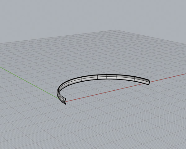
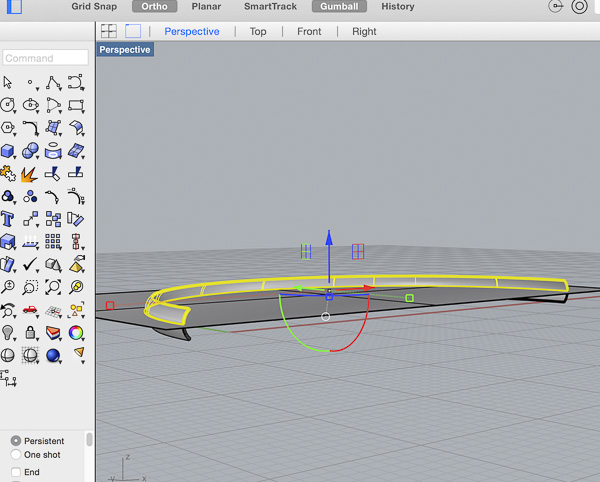
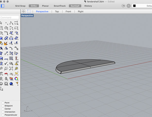
The next step was to design a semicircle with the right radius to act as a one part mold. First I measured a bikewheel frame, then the types of wheels I normally use, and room for clearance. I have been using OpenScad and some Sketchup up until this point for my 3D modeling, but it seemed like Rhino was a great program for curves, so I gave it another try. I created the arc of the wheel as a line first, and then extruded another curve perpendicular to the first, along the curve, to make the shape. This gave me a great fender to work from. In order for the Shopbot to be able to carve the fender though, I had to cut the model in half, which took a while to figure out but each step forces me to get comfortable with another icon and set of commands!
Working in Rhino to model a fender:

The next step was to close the shape and mill it on the Shopbot. Because of the 3D curve along the top of the fender, I had to use Partworks software to indicate the cut depths, orientation, etc. It had been awhile since working with this program, and I had gotten so used to V-carve, so it took a while to remember all the features. I exported my file from Rhino as a binary dxf file, and then exported from Partworks as a file as a .spb or gcode file for the shopbot.
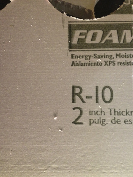
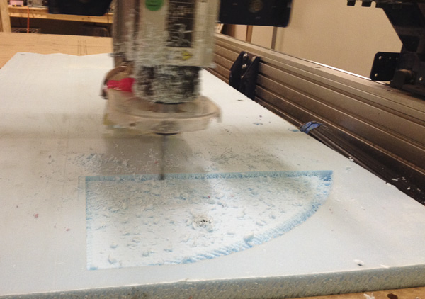
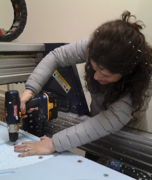
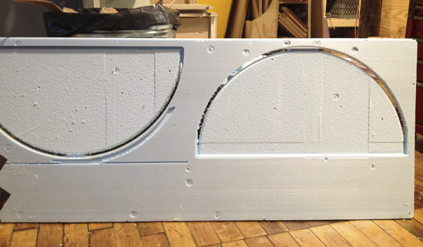
I screwed my foam (1” insulation foam) into the table with washers, only to quickly realize as the milling began, that I would have move them as the rough cut took material off the top. So I had to be very vigilant with taking the screws on and off to avoid yet another broken mill. Because we were trying to conserve material, before the second half of the fender was cut, I resent the file, flipping the model in Partworks. This ended up altering where the model sat in the material, as well as what the finishing cut versus rough-cut took off the foam. I was not happy as I noticed I lost 1/8” on the second pass of the finishing carve on the second block. After taking them both off the Shopbot bed, I glued them together. When dry, I sanded the edge and made the bottoms flush.
More time on the Shopbot but with a new material for me:

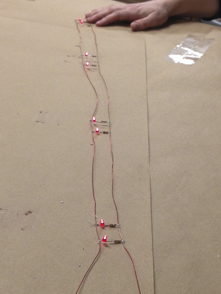
First, I had to put together my LED circuit, I stuck with the wire idea after debating using a copper circuit and surface mount components. I went with through hole LEDs because of their brightness. The circuit worked and all that was left was to lay a composite over the top of the foam.
Making the wire LED circuit pre-soldered:
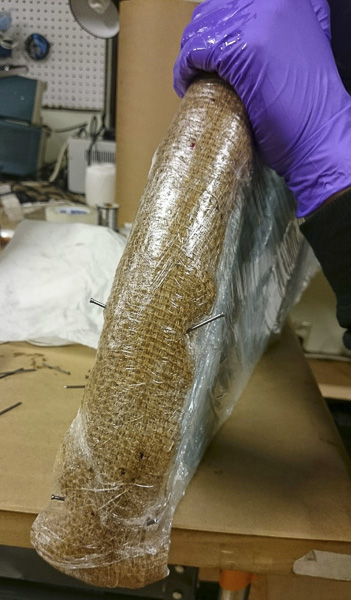
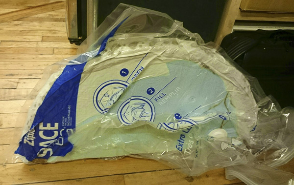
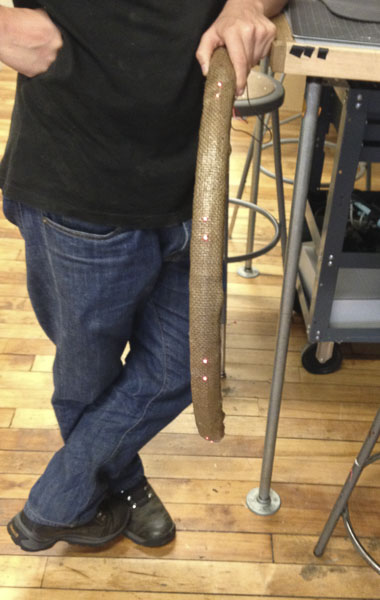
First, I wrapped the foam support in plastic wrap and shrink wrapped around it. I used 2:1 resin (epoxy), mixing approximately 2 separate batches of 1.5c each. It was difficult to get the burlap to stick to the foam, so I used little finishing nails stuck into the foam to hold it in place as I poured the epoxy on top. I embedded the LED circuit with 8 LEDs in the middle layer of the fender. When I had finished applying the resin, Kenzo helped me to wrap the entire piece in plastic wrap once again, and take out the nails. The next step was covering it with batting as a breather layer, and then stick the whole thing in a vacuum sealed bag.
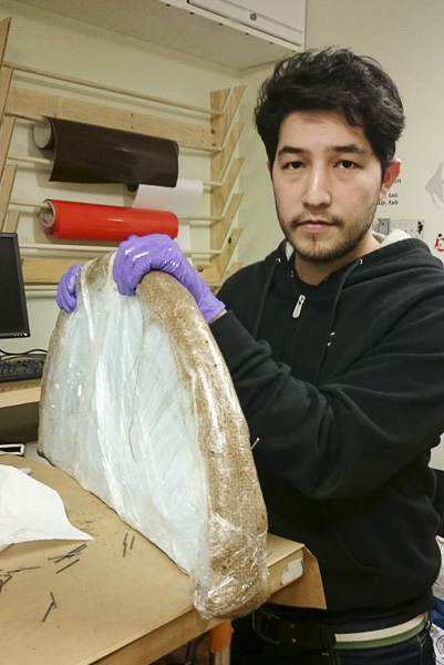
Burlap layered on top of the foam cutout:

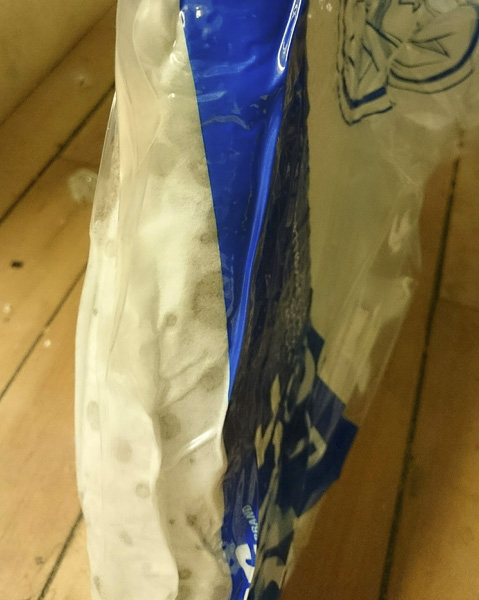
Vacuum bag to remove all the air. The resin can be seen soaking into the breathing layer:
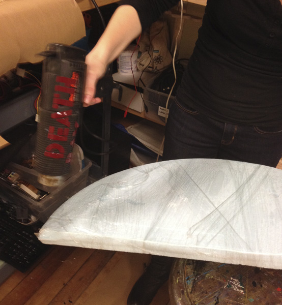
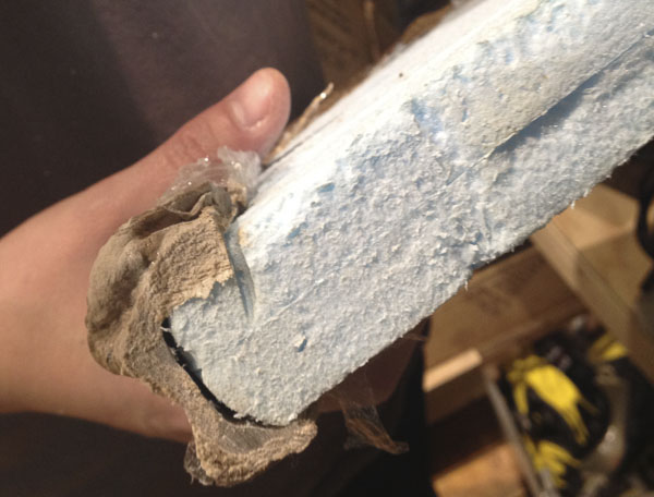
Although I did not cut my piece perfectly as Neal had suggested many times, I was able to get the somewhat lumpy bike fender off of the mold. The circuit worked and it is ready for install!
Getting the frame off of the mold:
Lights shining through the resin + burlap:
relevant files: