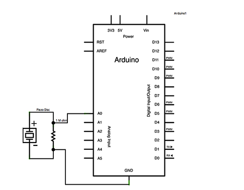
The instruction to design our own boards this week, with the addition of a sensor, forced me to get beyond copying the designs offered in the tutorials and weekly notes. While my final project is still evolving, I decided I would work on the laser that a cat could turn on by moving the scratching post. In order to perform this function, I chose to use a Piezo to read vibration. I am hoping to make it work like a switch, so that when it vibrates at a certain level, something will happen (a laser diode will come on).
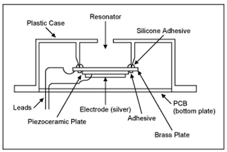
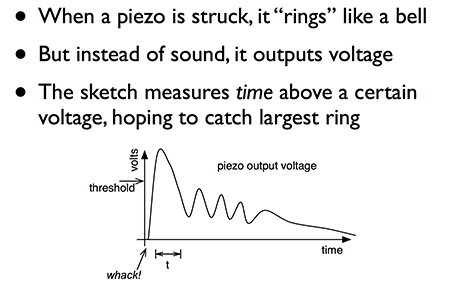
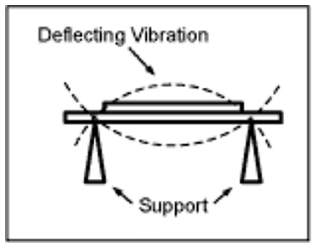
learning about how a piezo buzzer works:
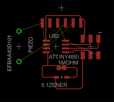
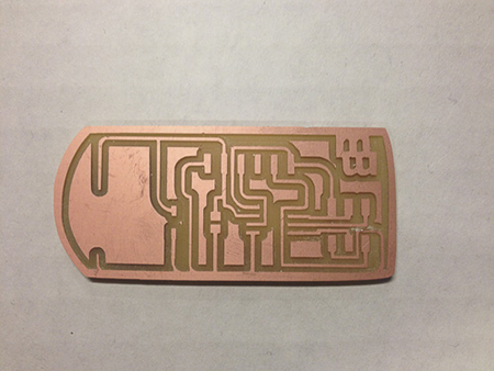
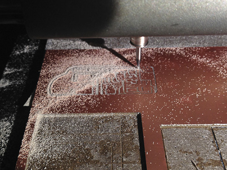
After setting up all the connections and pieces in the Eagle software schematic, I was ready to begin making the traces. I was having a hard time connecting some of the pads and was determined not to use 0Ohm resistors for jumpers. I moved around some of the pins on the FTDI cable and made all the components connect. If you are actually reading this, then you will immediately realize that this was a bad idea. I, sadly, did not realize this until much later…like after I had milled the board and was riding my bike to work later. Everything else about this process went really well. The bits milled sharp edges and though my traces were thin, they were all intact.
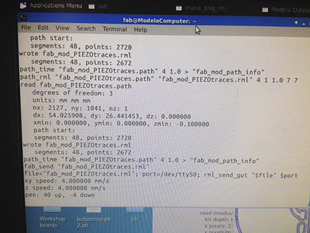
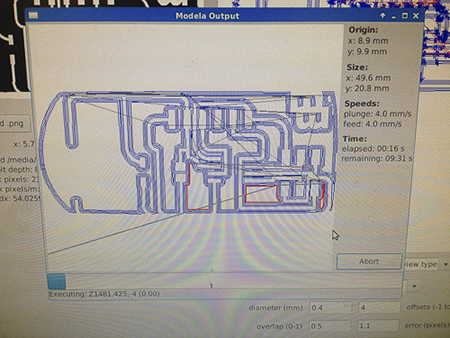
png-rml in fab modules:
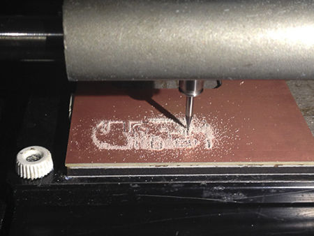
milling my first board:
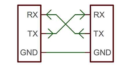
I got confused reading the data sheet and matched Rx-Rx and Tx-Tx!
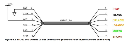
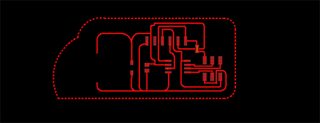
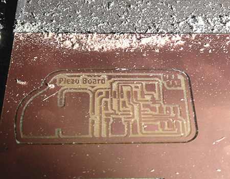
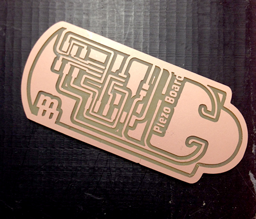
After realizing my mistake, I had to redraw the FTDI connections so that they mirrored the datasheet. This went much faster the second time. After drawing a basic board outline, using a 0Ohm jumer for one last connection that I could not figure out, I then pulled the image into Adobe Illustrator to create the vector path around the outside. The milling went smoothly again, with the default fabmodule parameters for png > rml.
realizing my mistake:
redesigned board being cut:
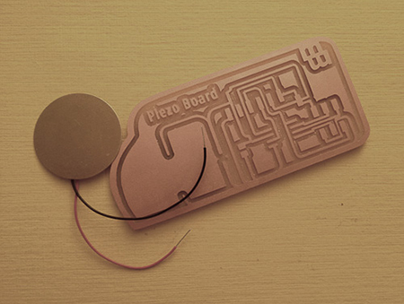
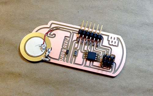
my second input board:
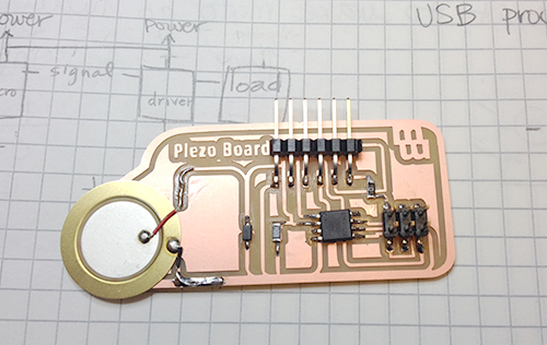
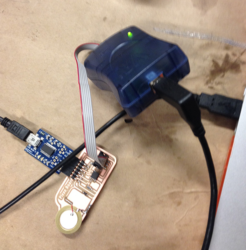
After stuffing my second board, I was able to begin the programming phase. We started by making sure we could connect with the serial port. I changed the specifications such as board, clock, processor, port and programmer to reflect the ATtiny85 with 8mhz internal clock and serial port: /dev/tty.usbserial-A4007Tqh. I used Neil’s modified program as follows:
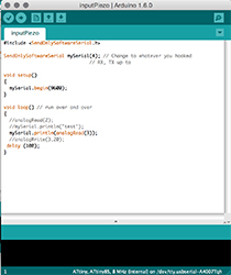
The initial serial print was a mix of symbols. I double-checked to make sure the connections were right and the piezo hooked up properly. The baud rate matched as well. Nadia helped me trouble shoot by checking my connections, and finally realized that my Rx connected to my RX instead of my TX. When I had gone back to look at the data sheet, I mimicked the FTDI line-up versus swapping the TX and RX position. My piezo continued to make a buzzing sound, that shifted when touched but was acting more as a speaker than a sensor. Nadia made an adaptor FTDI cable so that I could send serial in and it finally shifts in vibration of the Piezo. I did find that the Piezo on the board needed to be directly knocked to register a serial print of 80 or higher, otherwise, a shake gave approximately a 20-50 read.
I made a third board which did not use the RX or TX pins but rather the SCK pin so as to have a clean look. Yet after stuffing, I was not able to program my board. Initially, the Arduino error reading was that the programmer could not communicate with the sck pin. After some inspection, Kenzo and I decided that perhaps there was too little resistance on the trace from the microchip to the piezo and it was stalling the communication to the pins. After cutting the trace to the piezo, I was able to program the microcontroller but the serial print read was not giving information from the piezo. The read was showing the number 1023 continually. After adding another resistor and taking out a diode with no success, I left the board and went back to the first, hacked one.
My next step was to make a breakout board that would work off the piezo input to light a laser diode. While I wanted to go back and make the Fabkit/Fabduino version to further work with sensors, and interchange what kind of sensor I was working with as well as output, I decided to do that at a later point.
relevant files: