Final Project Prototyping
Page still under construction
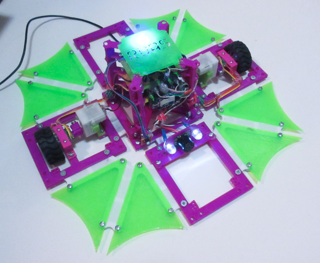
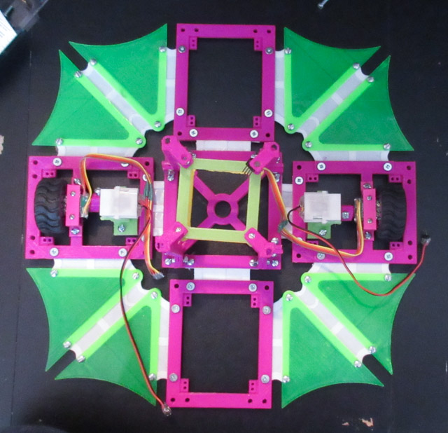
Final result
Making Of
Making the final project took place over a few days. It was crazy. Here are a lot of photos and thoughts from during the process. Sorry in advance if it's too many photos...
Pieces Prototyping
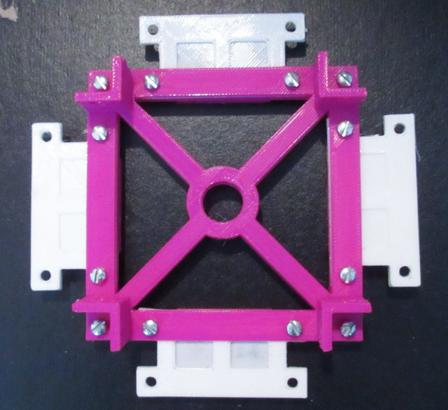
Assembled view:
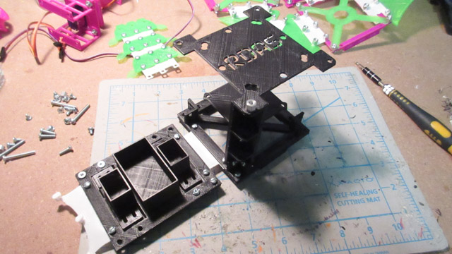
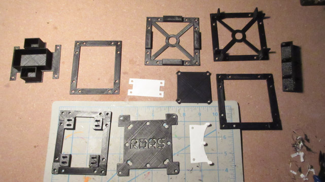
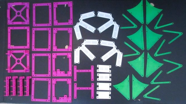
All of the pieces for the first iteration. It's one side, the base, and a few of the vertical related pieces:
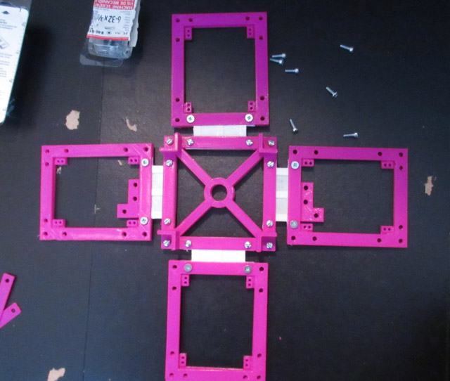
Partially assembled:
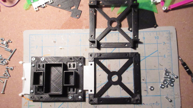
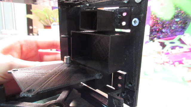
The rectangle extrudes w/ slots on the side piece were too close to the border, so it prevented the topper piece from going over it:
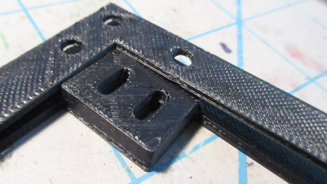
And also the size piece or any other piece that will be there in the future:
The solution was to just move it in the design by 2mm in both directions (and decrease its size by 2mm also, so that way it wouldn't mess up the side sizer estimate piece).
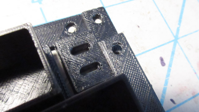
The holes on this piece are for the flexible connector to be insert. Except that it's blocked by the diagonal extrude on the vertical piece:

This idea of connecting the sides to the top to hold it as a cube did not work out. Not rigid enough, and the hooks kept falling out too:
The side size estimator piece gets caught on the diagonal extrudes:
Another angle:
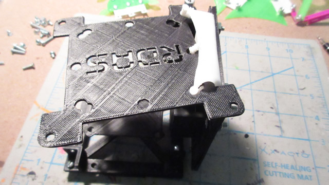
The size from the center of the base to the side is > 5 cm...
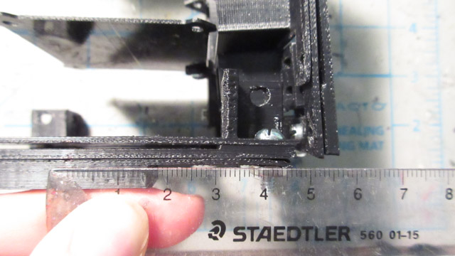
The height is exactly 10cm, but the width and length will have to be brought in a bit. Currently thinking of going for 20mm. Will also have to remember to resize the plates too.
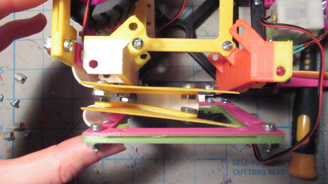
Folding Mechanism Idea
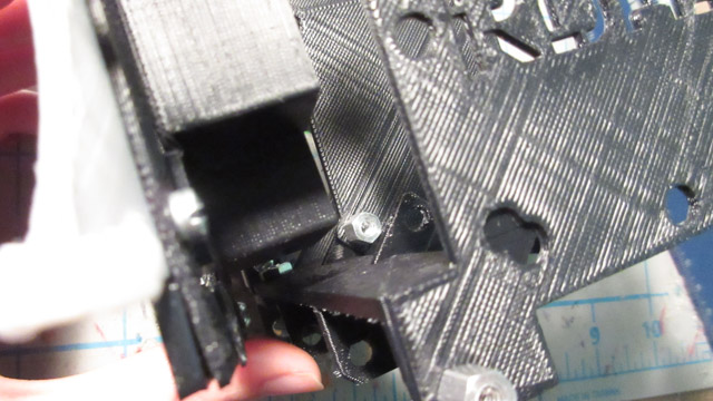
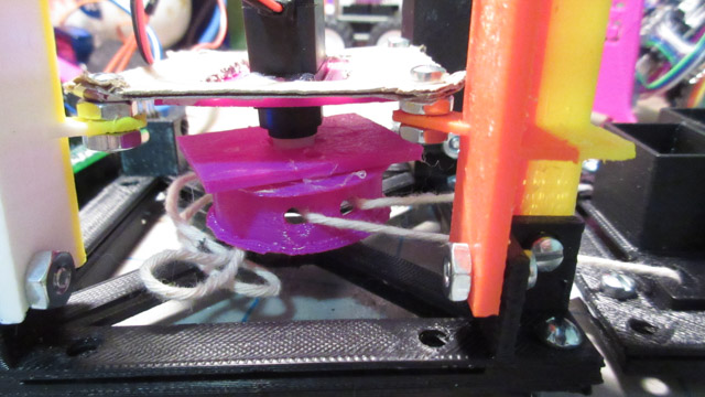
Tried out a way to make one of the sides fold inwards:
It uses a winch on a small motor. It might only be strong enough for one side.
One of the problems with RDAS v0.1 is that its left motor is intermittent. Something to do with the tab. Started to take it apart, nothing really worked. I probably can't fix the now loose wires inside of the motor. Also tried to move the gearbox to a similar motor, but the drive gear was slightly different.
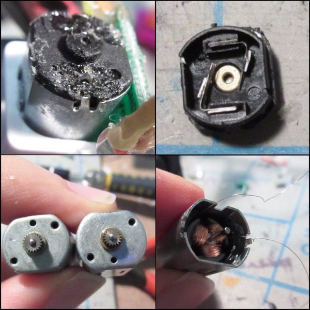
Mapped out what pins to use for the motor board and wanted to get the encoders working tonight, but got stuck on the motors for too long. So unfortunately can't use these motors, but I'll work a way around this problem.
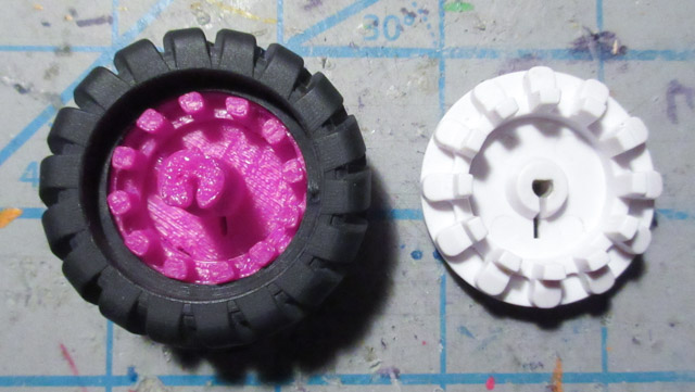
Re-Making Wheels
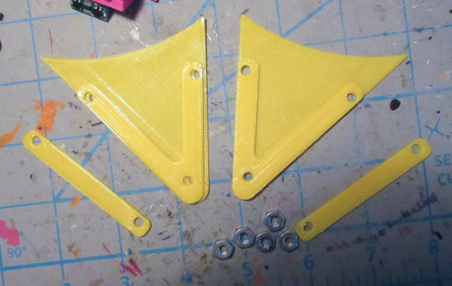
Tried a lot of ways to make new wheels. Such as driving a screw through the existing plastic wheel hub, and also tried designing a 3d part that can fit around the little nub on the wheel hub. In the end I went with designing a copy of the wheel hub and 3d printing it:
One of the problems of this is that the encoder tabs are not all exact. Some of them are slightly longer than others. It might interfere with the encoders.
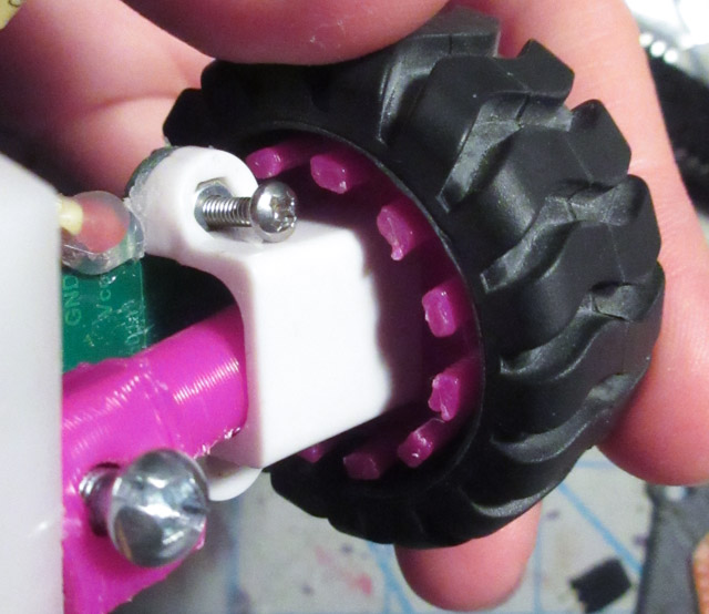
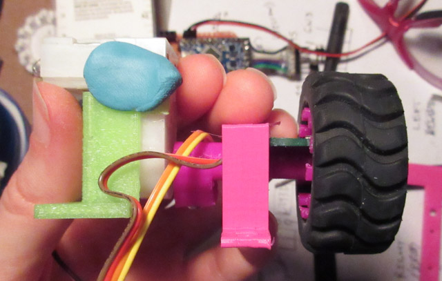
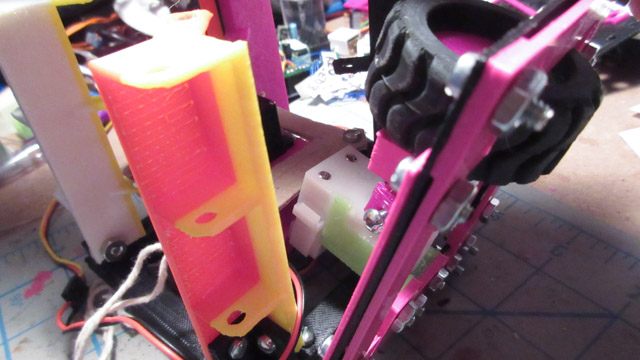
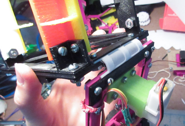
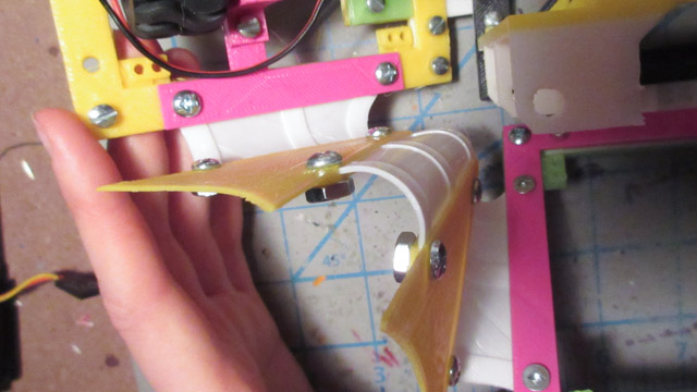
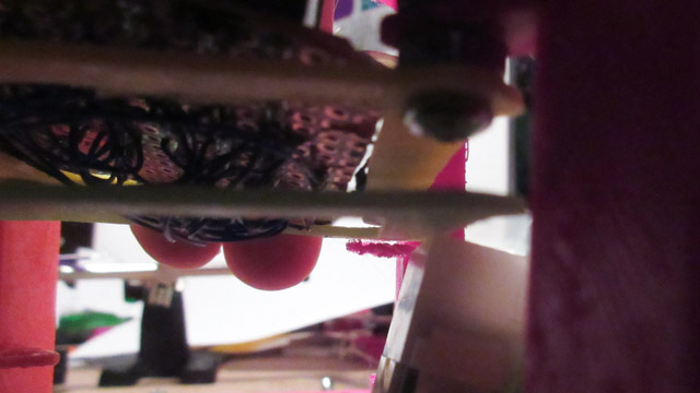
This is the side view of the motor assembly. The encoder board sits on the bottom of the encoder clip, where the sensors detect the tabs that spin by.
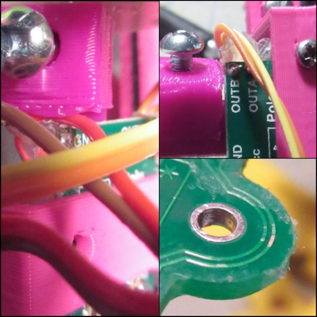
One of the problems encountered was whenever the motor would spin, sometimes its attachment from the axel of the motor to the wheel would get caught in the wires of the encoder. Also found exposed traces on the encoders (fixed with nail polish).
After assembling one of the sides with the wheels on it, tested it and it was able to move!
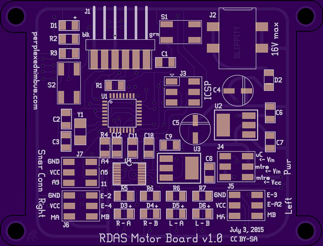
Motor Board
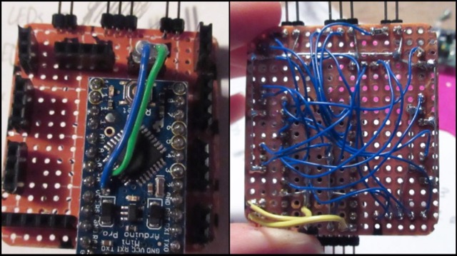
Here's how the motor board turned out:
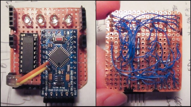
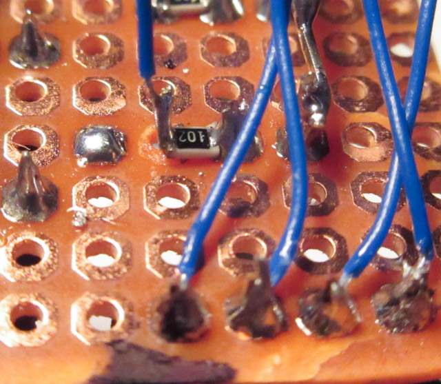
One of the problems was that sometimes the heat from the iron would cause the pads to lift off. Here you can see it happened with one of the sides where the 0805 1k ohm resistor was going to be soldered:
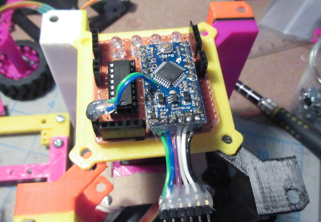
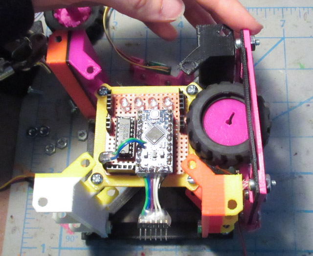
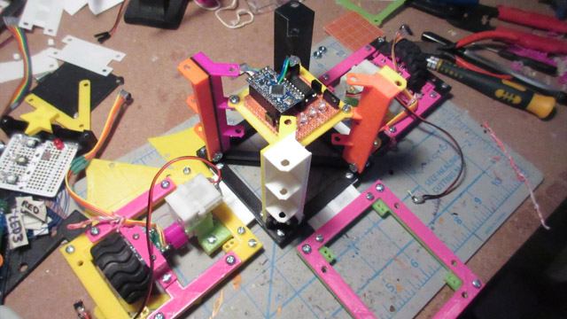
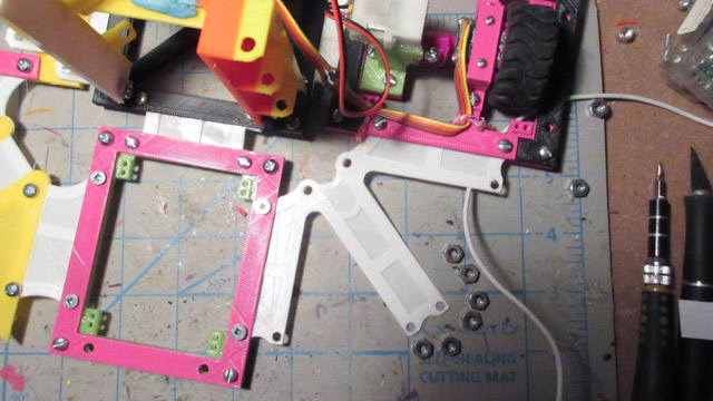
Here's how the board fits into the main area of the robot:
Todo: Coming soon will be a pinout diagram for the board, and a pcb version so that others can mill their own (and hopefully mill one for this robot too!!!!)
Pieces Prototyping
Created a revision of the size estimator piece, it now fits:
But the piece didn't really help all that much. Here, the motor is getting stuck on the piece that holds the winch motor for pulling in the sides:
Lucky- the location of this piece was not blocking the wheel of the motor:
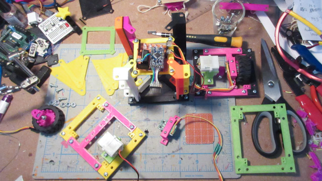
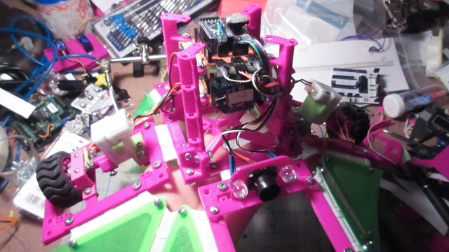
This is what the prototyping in process looks like:
Flexible Panel Piece
Rather than using 3 sepparate flex link pieces to attach the "solar" panels together, I wanted to go for one piece. Printed out the design on paper first to try it:
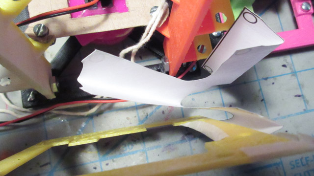
It seemed to work. The test panels will have a piece that clamps the flexible piece together:
Flexible Side Piece
Designing the flex side pieces required some trial and error. The sides are heavier with these motors on it. The flex pieces design from v0.1 was not dampening enough. I tested out differences on the base thickness, and the ribs thickness.
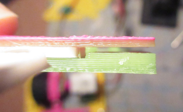
A problem of this change was that the indents in the base and side pieces were not matching. Leaving this gap. The piece is held in with its own screws, but with the corners screwed in it flexed the (rigid) piece, which is bad...
Bending all the flexible pieces:
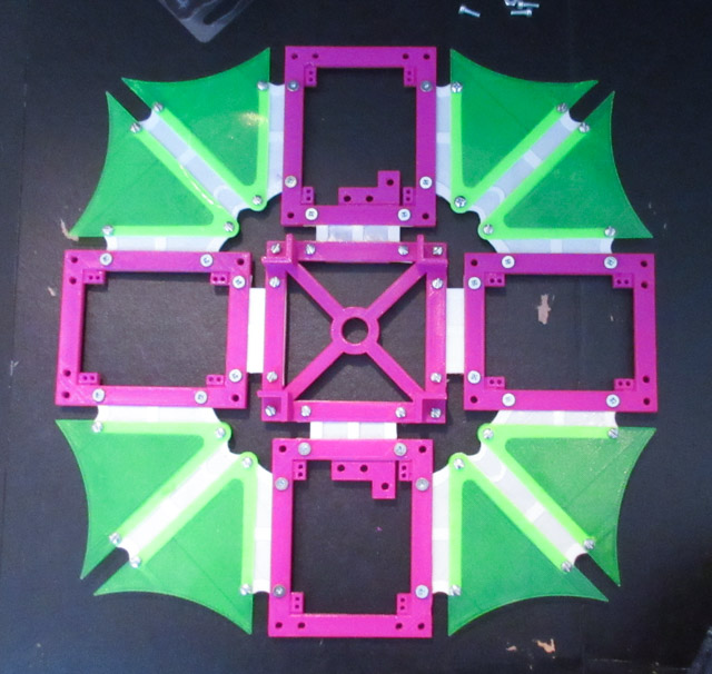
Building up the prototype
Added on the other sides to the prototype, this is what it looks like now:
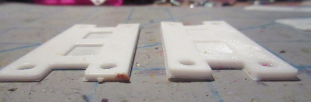
The 3d printer was working well!
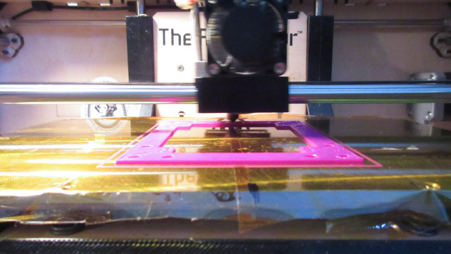
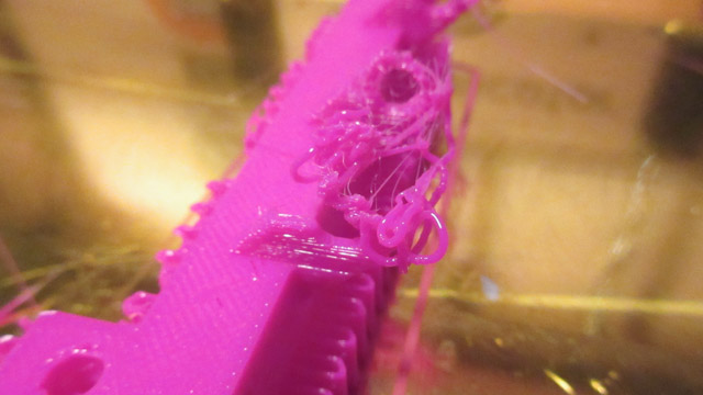
Except for this piece - I forgot to disable Cool so on the fine features it wasn't extruding enough (because it was retracting because of Cool). The print was fine after fixing this.
Meep
Folding Panel Flex Pieces
This is how the panels fold inwards... pretty dissappointing as they do not fold completely over because of the screws:
They are also smaller than the previous version, because I thought that by adding extra room for the flex piece to bend, that it would help solve it:
Flex view from above
Redesigned it to be the same size as the previous panels. But it won't be able to fold inwards unfortunately
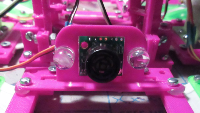
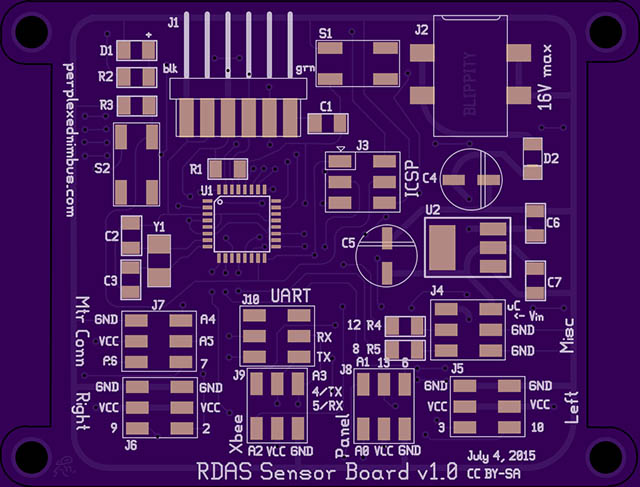
Sensor Board
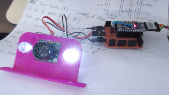
Here is how the sensor board turned out:
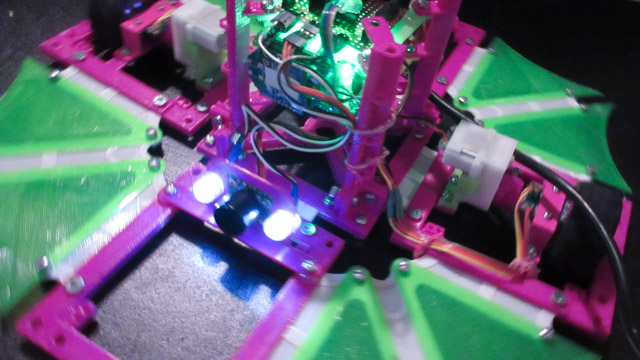
Testing it with the sonar sensor and leds:
Todo: Coming soon will be the pinout of the board as well as a pcb file
Scratchpad Status Update
The following was a quick status update at the halfway point before the deadline
Status:
- Prototype assembly seems to be working well
- Motor board soldered and tested
- Sensor board soldered and half tested
- Created an encoder test program
- Pieces for actual v0.2 assembly all printed
Challenges from this weekend:
- Breaking the motor for the gear motor then having to redesign how to make it work on different motors
- Glitching arduino pro minis that did not run the program the same way a Sparkfun arduino pro mini would
- 'Solar' panel folding still doesn't work right because the screws are too large and obstruct the folding
- Encoders not working as well as they should with the proper wheel rims. Spent a lot of time trying to calibrate the tiny potentiometers. Wrote a test program to collect data, used it for plotting a chart to see how long it would take each encoder to reach 24 ticks using various motor speeds (Pics coming soon)
- Soldering the wires takes a long time...
Tasks:
- Assemble the robot
- Motor board functions
- Sensor board functions
- Motor and sensor board communication
- Design & print top lock piece
- Testing
This might not be reached if not enough time:
- Headband soldering, code
- Headband communication
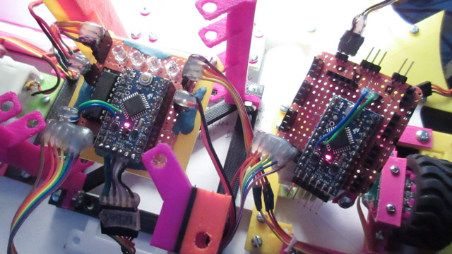
Both Boards Testing
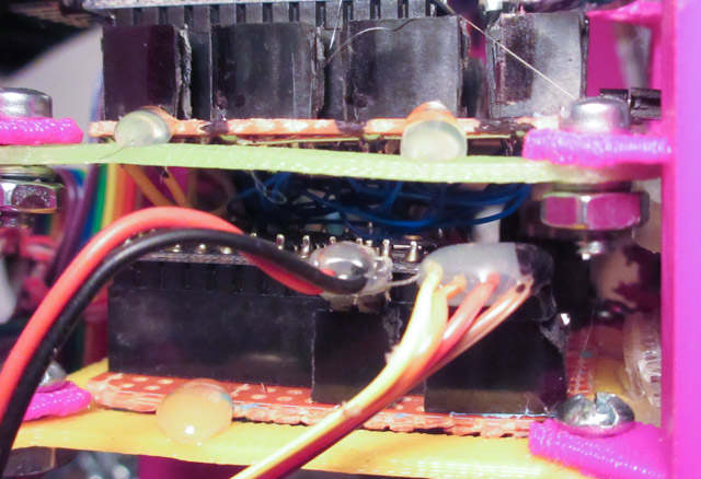
One of the problems I ran in to were the wires underneath the board being long enough to touch the other board that's on the 'shelf' under it:
With the space constraints, there wasn't much of a way to fix this- other than to just be careful when adding the boards.
Here are both boards being wired together testing in action:
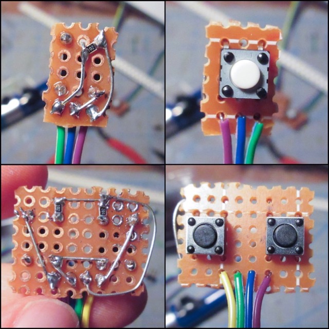
Here are the button boards:
Assembling
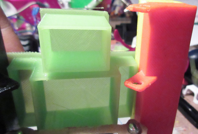
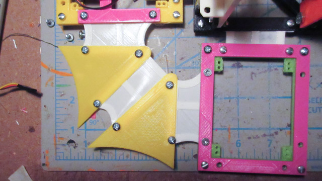
This is the difference between the flex pieces used for the sides, and the sides with the motors on it:
Here are almost all of the pieces:
The base is assembled with the bottom piece that has "sliders" on it, followed by the main base with the indents for the flex pieces, then topped by the vertical attachment piece:
The sides get attached to the flex pieces from here. Similar to the base- there is the main side piece with the indents, then a topper to 'clamp' down everything:
The panel pieces are added next, and the sides are fastened down onto it:
Then the motors and board holders are added:
Finally the sensor piece is added. It has a bit of an error though, because the printed piece is not tilted upwards. Meaning the sensor would not have a good angle at detecting obstacles infront of it. A temporary fix was to add blobs of hot glue to prop it up.
Here is what it all looks like:
Encoders
Todo: Add the graphs and info here
Coding
Todo: Add a flowchart here
First Test
First test!!!!!!!!!!!!
This issue is concerning. The wires are touching the Arduino beneath. But there's not really a way to fix it because of the space constraints- if the shelf moves down then the motors won't fold in.
Networking
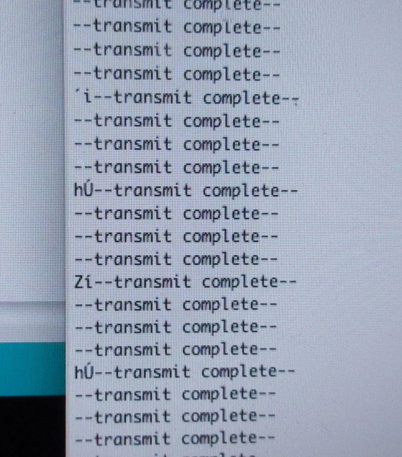
The sensor board is networked to the Tele-op Headband using an Xbee through the hardware serial uart. I encountered a problem where the Headband was receiving a garbled message:
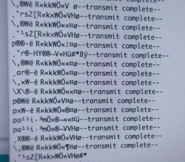
Seeing how some of the received messages had something similar in them, and it was somewhat long, I decided to double check the sensor board to see if it was sending something out, mistakingly. It was!
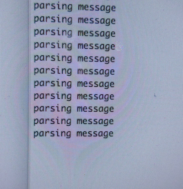
Caused by a mistake in my own library... The log levels are enumerated in decreasing presedence -- so the lower it is, then the higher its number. This should only be sent when it's DEBUG or lower, so it should be >=, not <=, which would include all of the log levels.
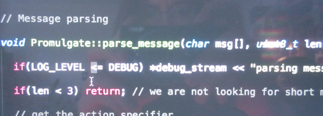
It solved the problem of sending the "parsing message", but did not solve the problem of not being able to receive the proper text. I have to look in to this problem more. The first things to check will be the wiring on the Xbee breakout boards, it's possible the RX on the Headband became loose. Transmitting from the robot to the headband isn't entirely necessary at this point, so going to move on. Luckily transmitting from the headband to the robot works fine.
RDAS moving forwards with heartbeat from Headband. This feature wasn't included with the demo presentation- but luckily enough because it would probably be going too fast and not noticable as a heartbeat. =)
Tele-op Headband
To see the making of and more documentation about the Tele-op Headband v0.2, check out this page.
One of the problems I ran in to with the headband was when nothing was working anymore. I tried so many things to fix it, and in the end the problem was I didn't solder two rows of perfboard together.
Here's a vine of the Headband sensing movement:
Final Result
Moving around, controlled with the Tele-op Headband!!!!!!
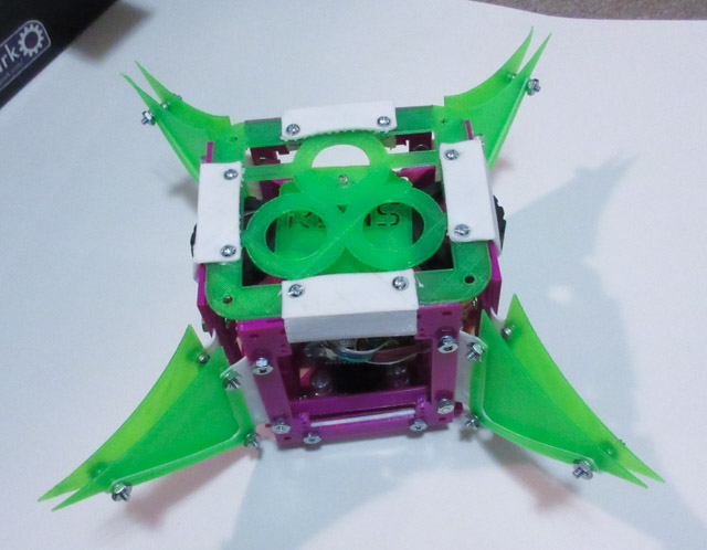
Here is what the robot looks like folded up. The clips on the top piece were printed with NinjaFlex (TPE)
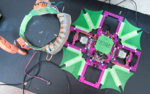
Unfolded and roving around:
Tele-op Headband and the robot:
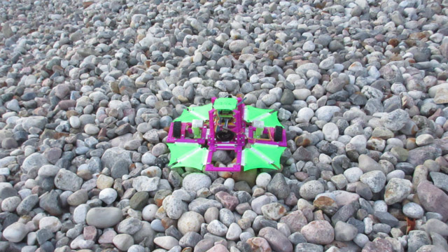
Bot out in the wild:
Electronics
Check out the Motor Board v1.0 and Sensor Board v1.0 here
This page isn't complete, here is the things still to add and do:
Todo:
- Add screenshots of design
- Program flow chart
- pcb design of the boards
- Encoder graphs
- Pinout of the boards
- Printer settings for the materials
- Finish the other Headband v0.2 page
For the next pages:
- Upload design files
- Bill of materials
- Dimensions of robot
- Weight of robot
- Evaluation of robot
- Ideas for making it BETTER!!!!!!