

So, my final project is completed. On this page you can find all the documentation and the last assignment for Fab Academy.
assignment document a final project that integrates the range of units covered, answering:projects can be separate or joint, but need to show individual mastery of all of the skills where possible, you should make rather than buy the parts of your project present your final project, weekly assignments, and tutorials
- what does it do?
- who's done what beforehand?
- what did you design?
- what materials and components were used?
- where did they come from?
- how much did they cost?
- what parts and systems were made?
- what processes were used?
- what questions were answered?
- how was it evaluated?
- what are the implications?
My final project consists of origami shapes you can put on your clothes. They change color depending on what you touch.
See Week 15 documentation, no significant changes. Only unlisted part in week 15 is mini usb connector, but this will not significantly change the costs.
The Color Sensor has two parts. A flexible PCB with a micro controller and a 3D printed ring which houses a photo-transistor and a RGB-LED. The RGB-LED blinks red, green and blue and the photo-transistors measures the reflection of light from each color. A red object will reflect more red light, a green object will reflect more green light. In the code I've set a threshold for each the measurement of each color which will calculate a color. The sensor can recognise six colors and white and black. After measuring, it sends the colors to I2C communication to the RGB Modules.
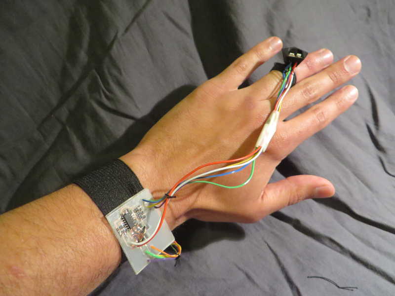
The housing of the ring is designed in Rhino. I used black PLA to 3D print it. I used very slow settings, half as fast as the usual 100 mm/s, because it is such a small object.
STL file 3d printed ring
The PCB is designed in Eagle:
Eagle files LED modules
The copper traces have been edited in Illustrator:
vector file traces
The program is written in C-code. It program reads the value and sends it via I2C communication:
Code.
For documentation on how I used I2C, read my assignment from Week 13.
The PCB for the LED modules is designed in Eagle. The LED is based on a seperate piece of polypropylene. I exported the led footprint from eagle and used Illustrator to make the tiny led-board. The base is of polypropylene and can be found below in the final polypropylene cutsheet.
Eagle files LED modules
I've used copper foil to make the traces (speed 1 cm/s, pressure 90). The eagle files were edited with Illustrator.
Traces LED-boardTraces individual RGB-LED
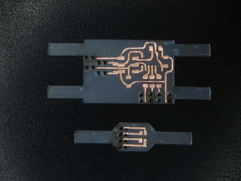
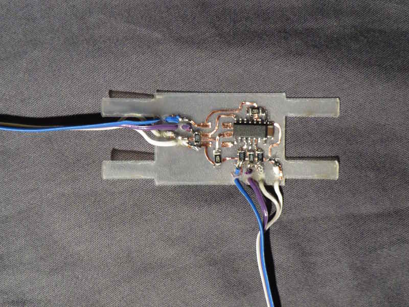
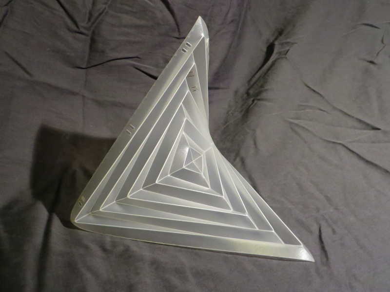
I used the polypropylene to make the origami shape. It is 0.5 mm poly propylene. With the laser cutter I scored the origami folding lines at speed 100/power 100 and cut it out with speed 3.8/power 100.
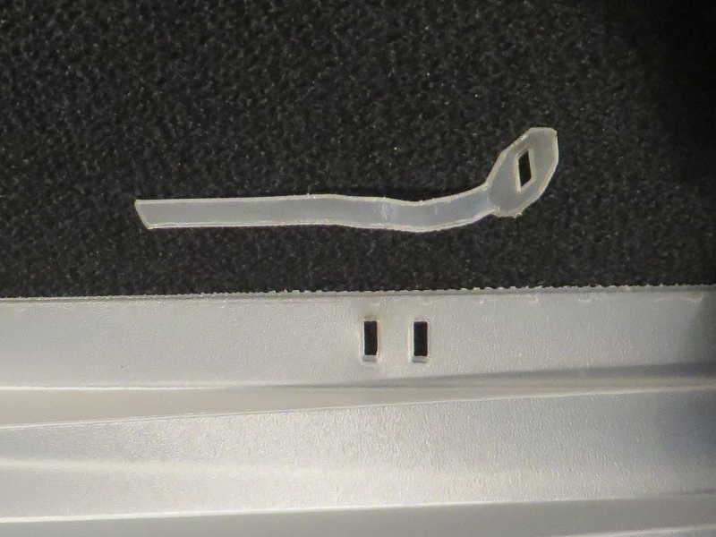
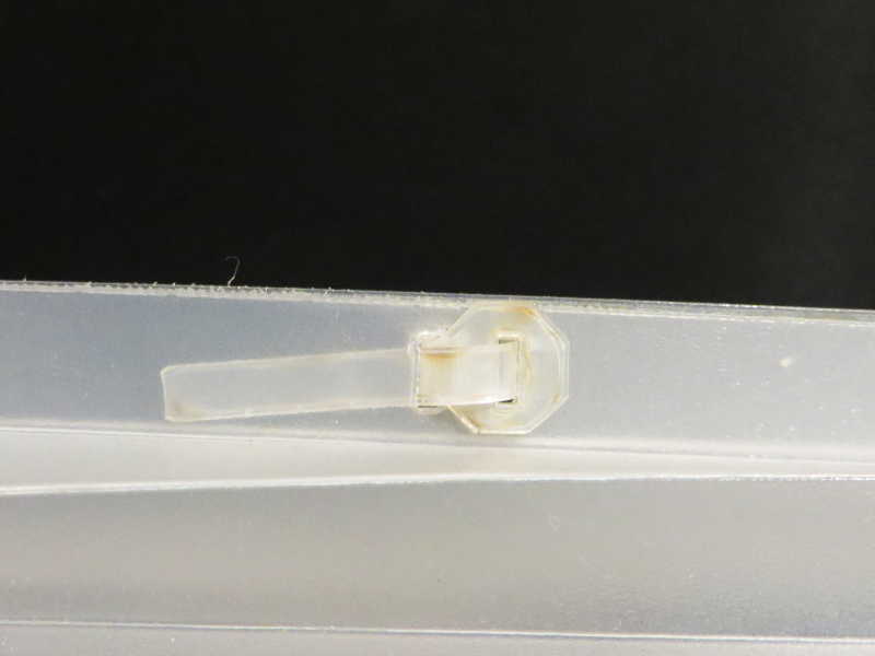
The design is based on a folding exercise from the Bauhaus Academy. I've redrawn it in Rhino and added a system to connect the pieces together and to connect the pcb's to the origami shapes. I've designed the connectors so I wouldn't have to use glue. It is not nice anyways, and it doesn't hold well on the material
Here is a cut sheet with all origami shapes, connectors, and pcb-bases:
final cut file polypropylene
I've finished my final project in time, so it is a successful end of Fab Academy. The sensor is working, the rgb-modules are working, however, more could still be added.
The project could be further developed. It can be sold as a finished product, or workshops can be hosted to learn other people making similar things. Safety considering wearables and electronics have to be improved though, and the origami design can be altered. For more implication see my assignment for Week 17.
