For the Networking and Communication assignment I took up the challenge to do I2C for ATtiny 44 using C code. I struggled with the C code, but I'm really a beginner in programming, but in the end I managed and learned a lot about ATtinys, I2C and C language.
I wanted to use the ATtiny 44 in stead of the ATtiny 45, because it has more pins so you can make a more extended board with it. I've been using them in most of the other circuit boards I made in Fab Academy, so it seemed like a logical step to learn how to make these ICs communicate. I think I2C is a nice protocal to let them communicate, since it had a shared clock and can connect multiple slave/nodes with on only two wires.
design and build a wired and/or wireless network connecting at least two processors
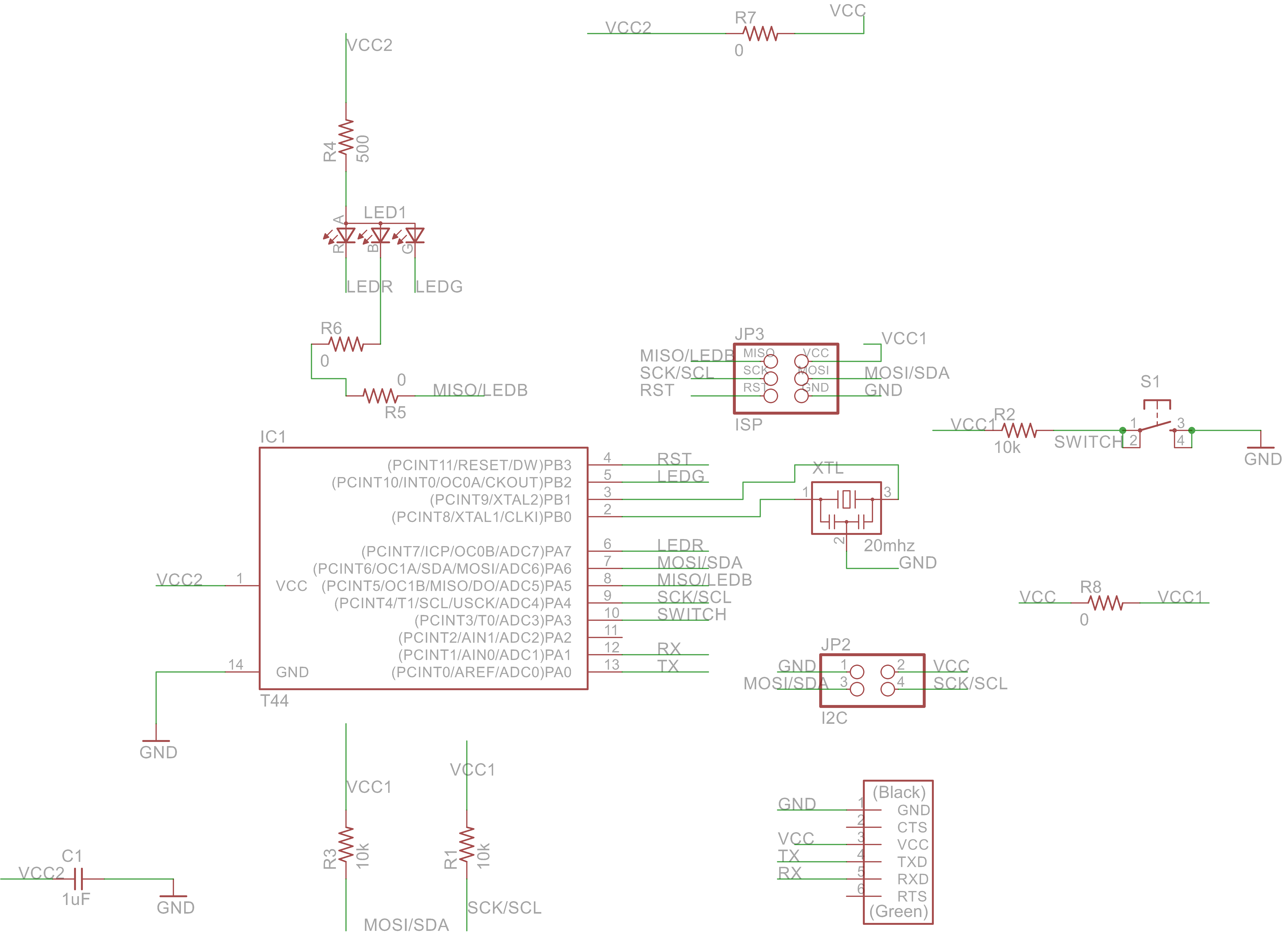
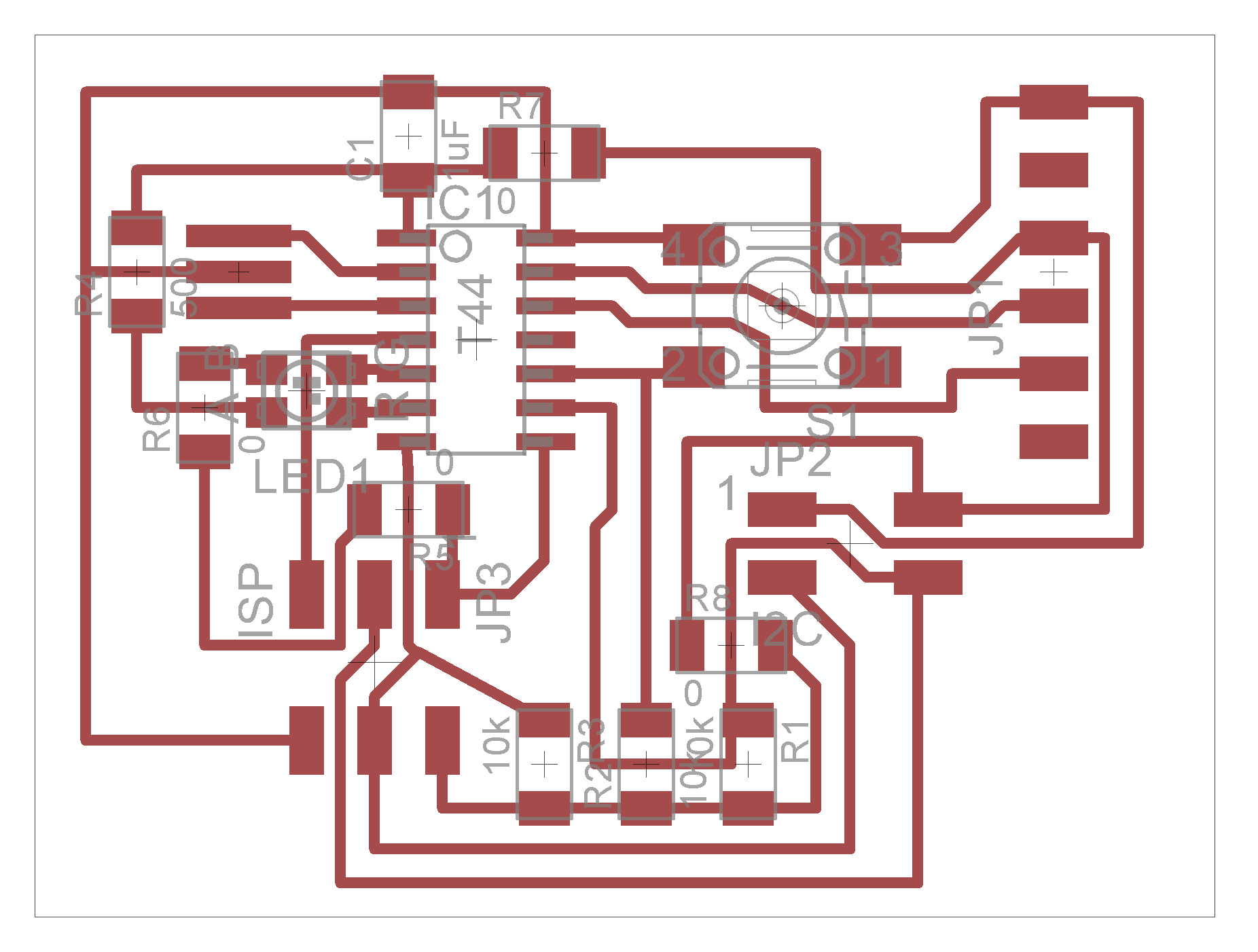
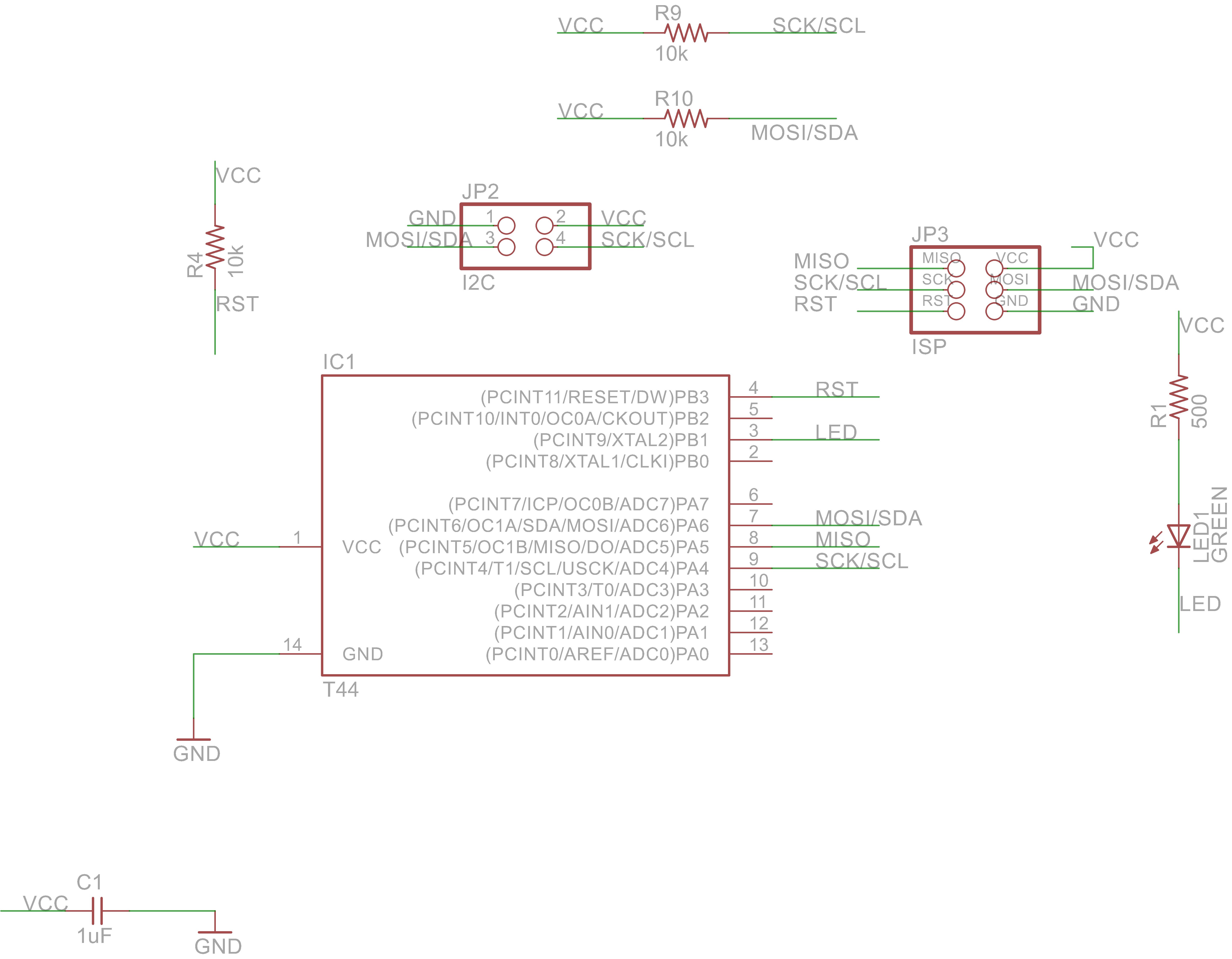
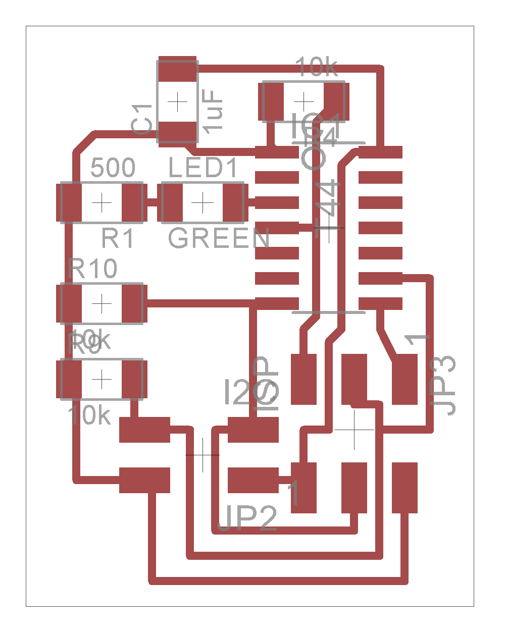
I designed a bridge and a node board in Eagle. I used ATtiny44s on both, added a button and RGB-led on the bridge and a led on the node to create be able to have inputs and outputs from the code.
The boards are connected through four pin headers. I2C communication requires a wire to send data (SDA) and a wire to share the clock (SCL), the other two wires are to share GND and VCC.
I think I made a mistake in how I connected the RGB-led. I limited the resitance on the side of the common anode, I thought that would be an easy way to save some resistors. But I didn't think of the fact that this wouldn't supply enough current to power the colors at the same time, but I can do two I guess.
Designing the boards, routing the traces, milling and soldering are becoming a bit of routine, that was the easy part this week. For the programming I first read more on what I2C is, how it works and how to implement it on a ATtiny44. First thing I learned was that there are different names for I2C, for example IIC and TWI are also used for this kind of communication. Also, the terms slave and master are instead of node and bridge.
I based the C code I used on an application note from Atmel, the producer of ATtiny: Atmel AVR310: Using the USI Module as a I2C Master and AVR312: Using the USI module as a I2C Slave. As you can see, Atmel uses the terms Master and Slave, to I will be using these terms from now onwards. These application notes come with an example C-code, a library and some documentation. I read through the ATtiny44 datasheet a couple of times before I kind of understood what was going on.
There were a few obstacles in the C-code. First of all, there were two pieces of C-code I somehow had to compile together. So I had to find a way to include all the pieces of C-code in the makefile. I did this by setting the sources in the C-code to all the .c files in that directory: "SOURCES=$(wildcard *.c)". You have to whatch out that there are no other .c files in the directory.
The code for the Slave was written to be compiled with IAR, in stead of GCC which I'm using. I had to rewrite the code to make it work with the GCC compiler, because there are some differences the libraries they use and for example in how vectors are defined. You can read more about this on the AVR Libc websiteI replaced the ioavr.h and inavr.h with avr/io.h for GCC. In the code itself I replaced
__enable_interrupt(); with sei(); __no_operation(); with asm("nop");#pragma vector=USI_START_VECTOR with ISR(USI_STR_vect)
#pragma vector=USI_OVERFLOW_VECTOR with ISR(USI_OVF_vect)I also had to edit the device dependant definitions in the I2C libraries from Atmel, because the ATtiny44 wasn't included. I looked up the right ports etc. in the datasheet.
// Device dependant definitions for ATtiny44
    #define DDR_USI             DDRA

    #define PORT_USI            PORTA
    #define PIN_USI             PINA
    #define PORT_USI_SDA        PORTA6
    #define PORT_USI_SCL        PORTA4
    #define PIN_USI_SDA         PINA6
    #define PIN_USI_SCL         PINA4
    #define USI_START_COND_INT  USISIF
    #define USI_START_VECTOR    USI_STR
    #define USI_OVERFLOW_VECTOR USI_OVF
So after I knew how to compile the code and edited te libraries to work with ATtiny44, I could start editing the code to make it communicate between the boards.
I build up the code step by step, to see if the everything was working the way I thought it would. So first I programmed the boards with simple codes to check the LEDs, button and FTDI communication. This also took me a while.
I used a bit of code to test the button, but it didn't work, because I didn't realise for a long time the the code was written for a button with a pull-down resistor and I have a pull-up resistor.
The LEDs on the master board weren't working the way I wanted, because I made a mistake with the resistors, but I can blink the red and the blue light seperatly now.
I uploaded the hello echo program from the embedded programming week to check the FTDI communication and this worked perfectly. But when I put the different pieces of code together, the FTDI communication failed. After checking this in all the possible ways (reprogramming the clock, using an arduino sketch to check the clock) in the end I found out that I just mixed up the pins in the code.
After I had that all figured out, I could start editing the code from Atmel. I had to do a few C-tutorials, because I had never seen a switch-case loop, but the tutorial cleared things up. Tutorial link
Now I have a program running that can send data from the master to the slave. The master sends a value and the slave stores it in a variable. If the variable is the same as the master has send, the slave blinks the LED. Also, the master sends out an error message to the FTDI is commucation failed.
Here is a link to the files I used for the master, the code is very messy, so I have to clean it up, but just to get a look:main.c The other two files you need are in this zip-fileUSI TWI Master library + c-code