After the tiny electronics last week, Week 8 of Fab Academy was something entirely different. “Make something big” was the assignment. I haven’t got to the point that I actually made something big. Since there are quite some Fab Academy students at Waag, machine time was limited. Also, my design wasn’t that straight forwards. So this week I did a lot of test runs, redesigns and waiting to do another test. Even though I didn’t make something big yet, I did make some building blocks which can easily be turned into something big if the ShopBot is available again.
My experimenting lead to a design for a curve and a corner joint for boards. Both were done in plywood, which I think is really nice to work with. It is very strong, yet flexible, due to the varying directions of the wood grain in the different layers of the plywood. I managed to make two types of stable wood joints without using glue.
this week's assignment:
make something big
The Curve
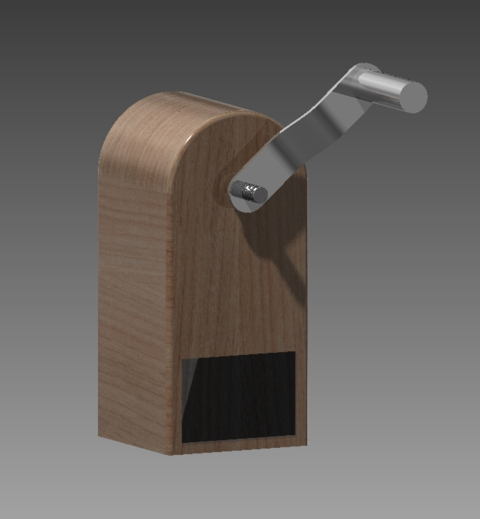
I wanted to examine this kind of curving in wood, because the design I made for the final project proposal has a bend like this. Since my final project has an electric generator in it and is going to be part of an exhibition where also kids might come by, the housing has to be strong. This week was a good way to examine ways to reach this.
I did the modeling and designing in Rhino this week and I’m really starting to get into it. Especially with the Grasshopper plugin to do parametric design it is a very powerful tool.
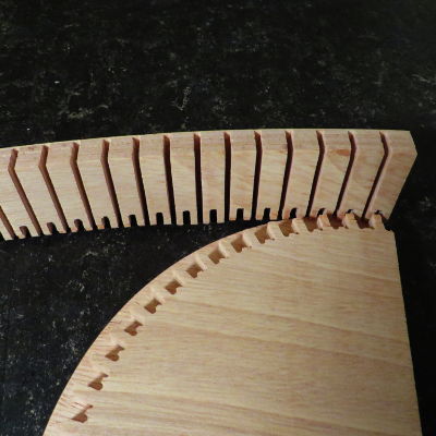
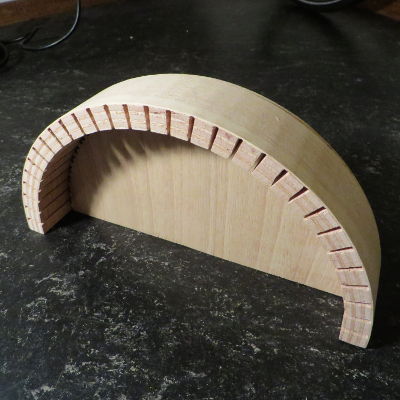
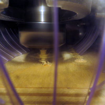
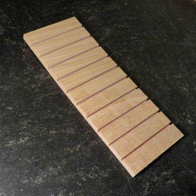
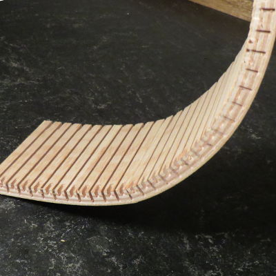
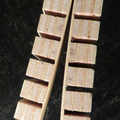
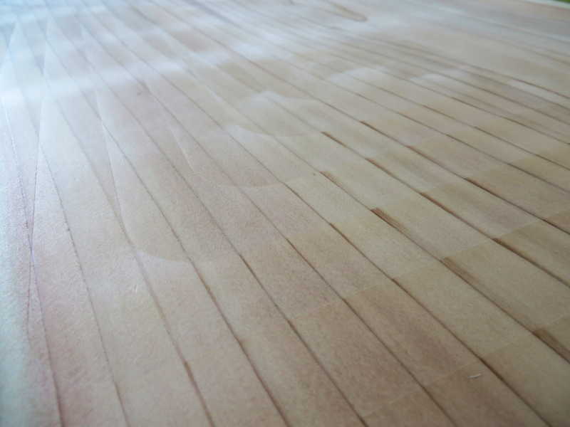
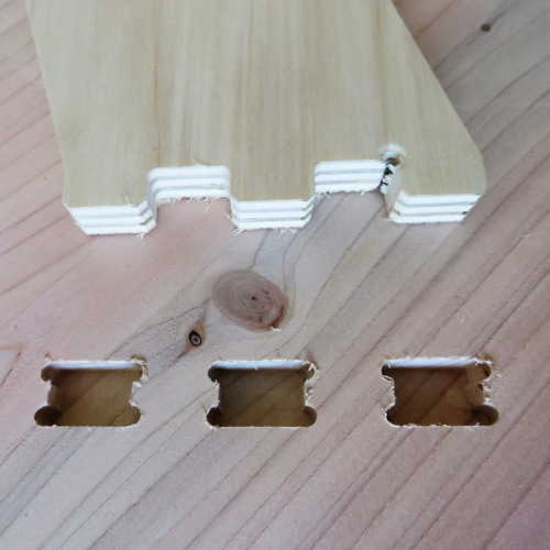
The type of wood bend I was trying out is called a kerf bend. Basically you just make cuts in the board and leave just a few millimeters of wood, which should be thin enough to bend, but also flexible enough so it doesn’t break. After a full day of instruction on how to use the machine, I began with a really basic milling job. It was a rectangular cut-out with 10 kerfs in it. In my file I drew the kerfs as a line, not a surface. Then I set the tool path up so it would mill in the middle of the line in stead of inside (like a pocket) or outside (profile). This way you make sure the cuts are as narrow as possible: not wider than the mill is. Also the tool path is very straightforward which is time-efficient.
First experiment
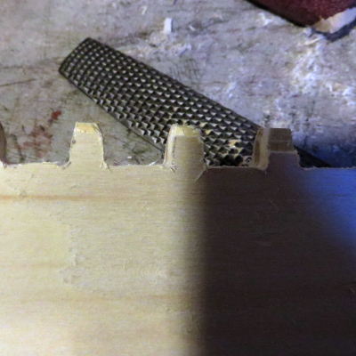
I set the milling machine to leave 2 millimeters of material. Results: it did bend a little, but broke fast after that.
Evaluation:
- cuts were not deep enough.
- next time more cuts. The wood bend a little, but one kerf can only bend a few degrees until it breaks, more cuts should result in more bending.
- Also, it was hard to keep in place, so I designed an arc with slots to keep the next bend in place.
Second try
Much better, more cuts resulted in a more flexible piece of wood. However, it only bend about 90 degrees, where my goal was 180. After 90 degrees it started to break. This might also have to do with the direction of the wood grain. On top of that, I found out that plywood wasn’t completely flat after measuring the depth of the different cuts. There was a difference of 0.5 millimeters between the deepest and most shallow cut, which is a lot if when the remaining layer is only supposed to be 2 mm thick.
So this time I could not yet see if the system with the arc works, since the piece didn’t bend enough to fit the slots.
Third try
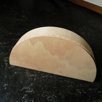
The third and final try was very successful. I decided to make two kerf bends, one with of 1.5 mm and one with 2 mm of plywood remaining. But most of all, the direction of the wood grain seamed to be crucial. If the grain of the final layer is in the same direction of the kerfs, it breaks, if it is in the opposite direction it bends. The 2 mm version could make the 180 degrees I aimed for, but this is about the limit. The 1.5 mm version is very flexible and can almost make a 360 degrees.
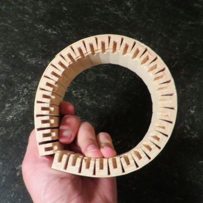
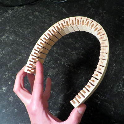
Now I could also try to fit the bends in the arc. It didn’t fit well at first. I could force the studs on the arc into the curve slots, but than they started to break. I redesigned the arc so there would be 0.5 mm extra which was exactly what it needed. Connection the arc and the curve was a bit tricky in the beginning, but after I figured out to first bend and then push it in, it was quite easy. The last few millimeters needed some pressure, but once there both the 1.5mm and 2 mm version stay in. The outward tension of the bend holds the joint together tightly without any need for glue. It is a closed wood joint, so from the outside you can’t see the connection which gives it a very clean look.
cut file arc and bend
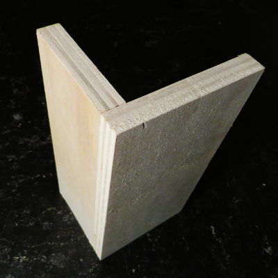
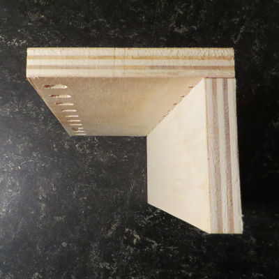
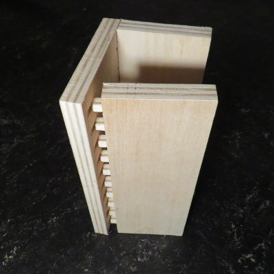
The Board Joint
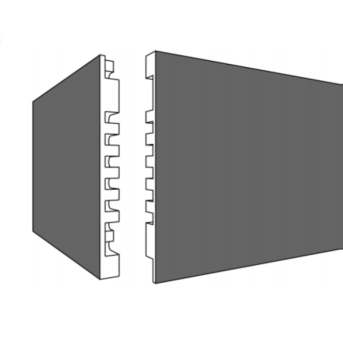
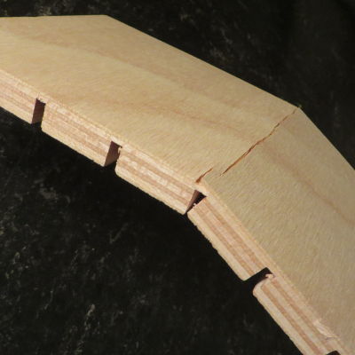
The other wood joint I did this week is an adaptation from the ‘Secret Fingertip Tenons’ joint in the 50 Digital Wood Joints collection. I want to use this wood connection to make a frame in an exhibition. In it will be a panel with a historical timeline and I thought it would be nice to keep the surface of that panel completely clean. Therefor I tried the hidden wood connection. My version is different from the one in the 50 Digital Wood joints, because mine is asymmetrical so one side is a completely clean surface.
I did the design for this connection in Rhino with the Grasshopper extension. This way I could use some parameters in the design which I can easily adjust. For example when using material with a different thickness or the connection needs to be slightly adjusted for a perfect fit. I followed this tutorial to get started. I did a bit of parametric design in Week 02 and 03 of Fab Academy with Antimony and quite easily get along with this plugin.
I only made a first version of the connection, but it turned out rather well. I forgot to put chamfers in the design, but after I manually sanded down the corners I fitted the pieces together. It is a very tight fit, I had to hammer it in, but it won’t come apart easily now. There is a tiny gap between the two pieces which I can avoid in the next version by changing the shape of the slots. I can’t wait to have another go at the shopbot and make some things with the wood connections.
cut file board joint
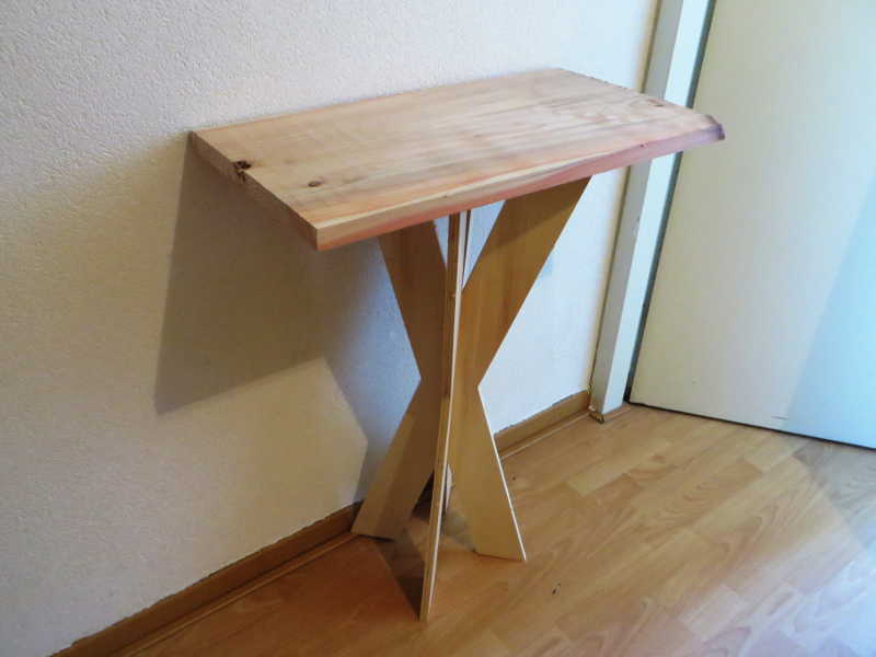
Table
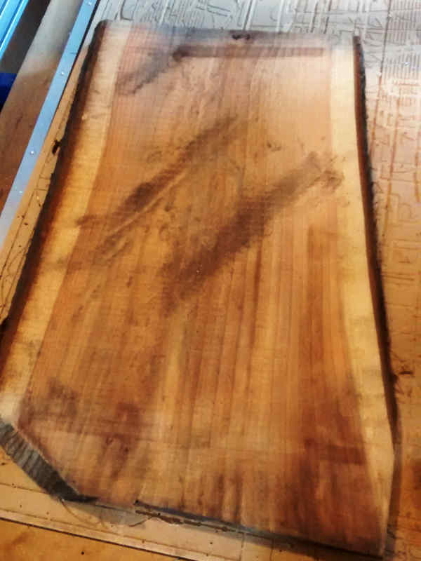
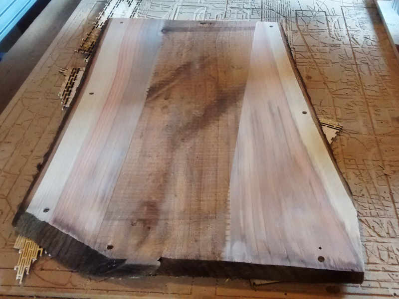
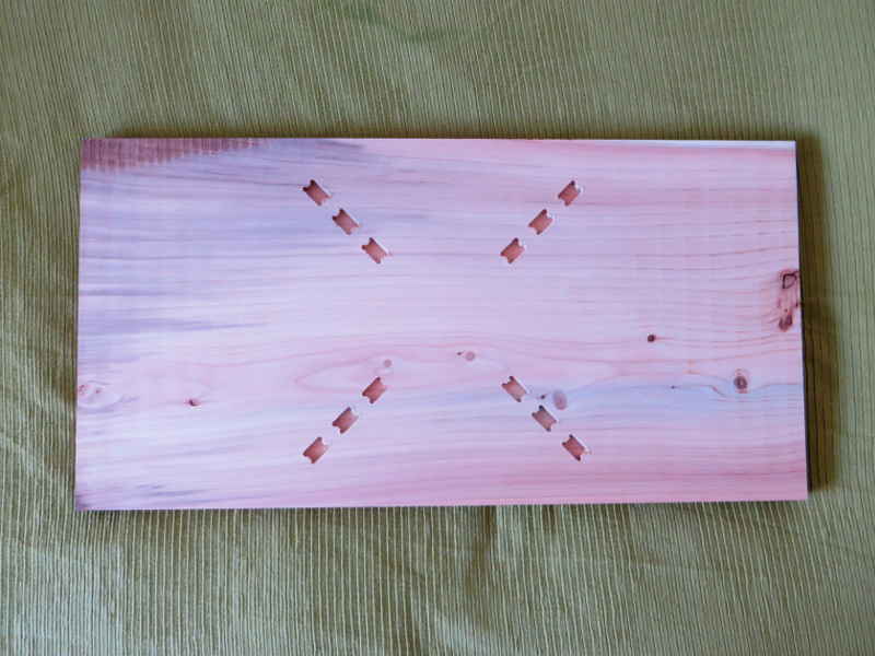
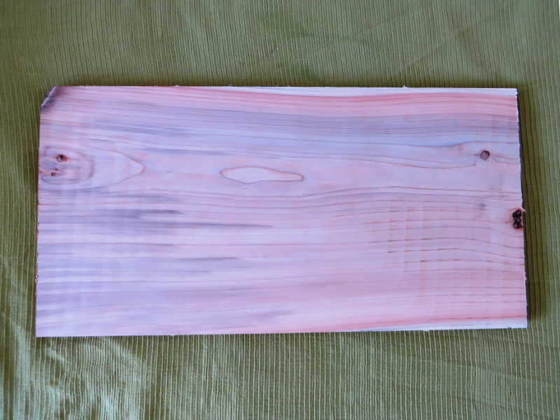
I started out with a rough piece of wood I saved from being burned in a campfire. It is a leftover bit of 'city wood'. The three it came from was standing in Amsterdam-Noord, on the Van de Pekstraat, but they had to chop down the tree because of large scale renovation of the neighbourhood. The city of Amsterdam decided to give back the trees to community projects in the neighbourhood which is were I found it, there wasn't any use for it anymore, so I used it for this project.
The wood is from a Swamp Cipres. It is very soft wood and it has a beautiful pink color.
Surfacing
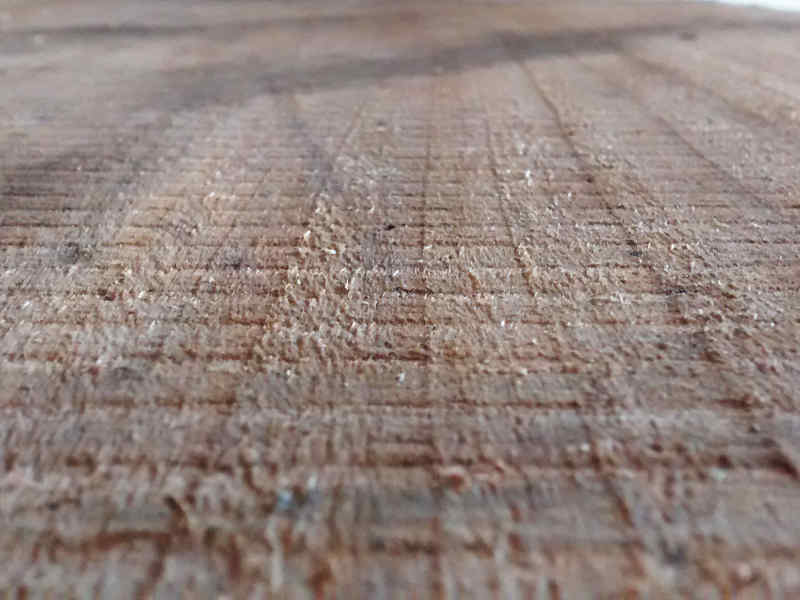
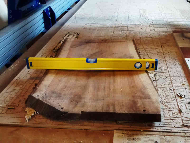
Because the piece is bend and rough, I first needed to do a surfacing job. This is a milling job in which you gradually mill down the surface of the wood, until you have a flat piece.
You want to take away as less material as possible, to keep the thickness of the wood. The best way to do this is to level it, so that you are taking away the extremities at both edges and keep the thickest part in the middle. I leveled it on the machine bed by putting some scrap pieces of wood under it, checking if it is leveled with a spirit level and fixing it in place with screws.
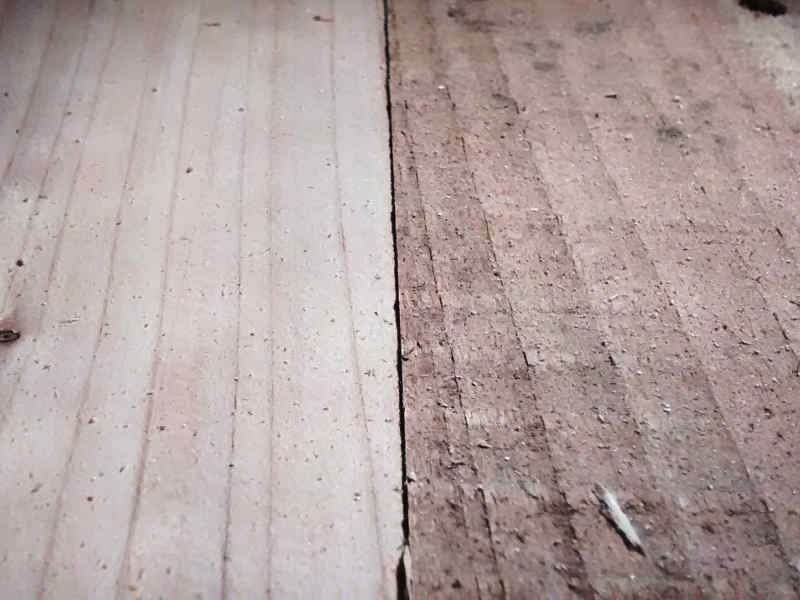
Tools and settings
The tool I used for the surfacing is a 2 inch (about 5 cm) flat end mill. This end big mill evenly scrapes away the wood and leaves a flat surface. I used a pass depth of 0.5 mm, stepover of 48% and a feed rate of 100 mm/s. I started out with a slower speed rate, but 100 mm/s was fine, because the wood was so soft. I think I could have used a deeper pass depth, because the wood is so soft, but wasn't sure so kept it safe and used the presets.
The tool path for surfacing is basically a pocketing job in the shape of you piece of wood, so a square. For the sides that were much above the rest of the surface I did a seperate surfacing job, to mill down the extremities first. I ran separate jobs. Starting by milling a few millimeters and after that millimeter by millimeter. I took away 1 centimeter on both sides.
Stand
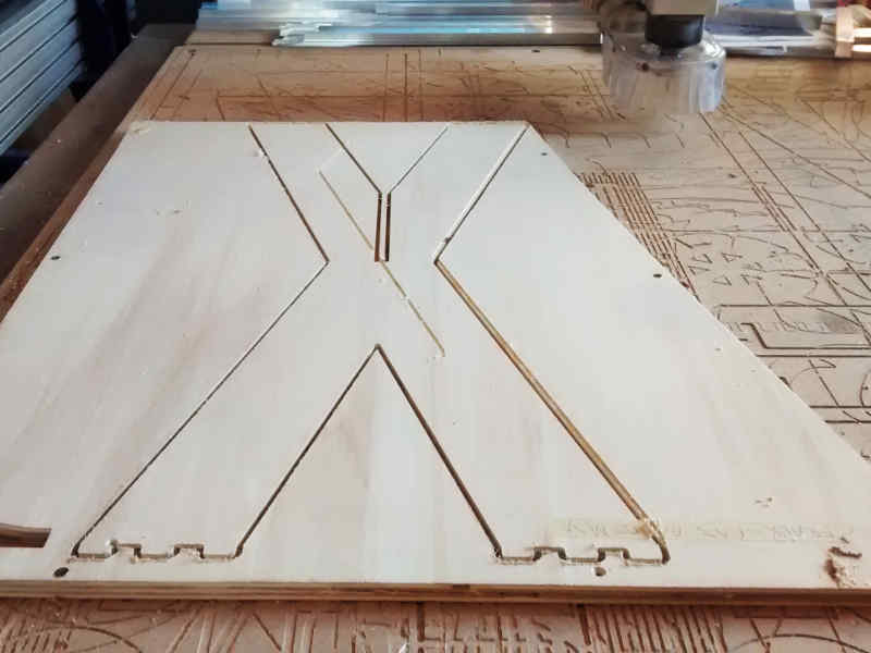
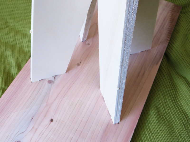
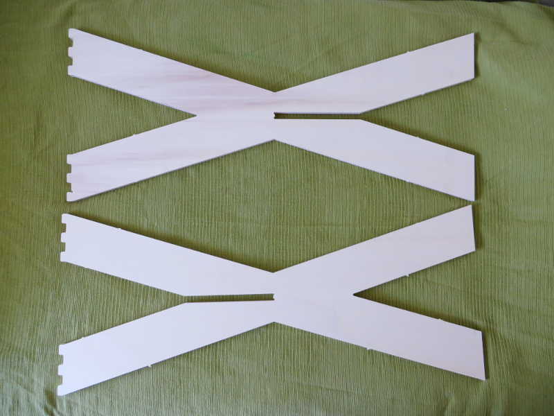
The piece of wood for the surfacing job was only enough for the table top, so I needed to make a stand from other wood. I found some leftover pieces of plywood in the lab and decided to use that. I believe it is birch plywood, because of the light color. I designed a simple stand of two pieces that slide together in an X shape.
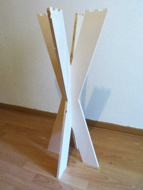
Connections
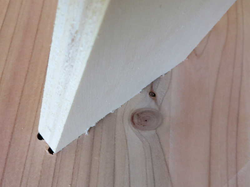
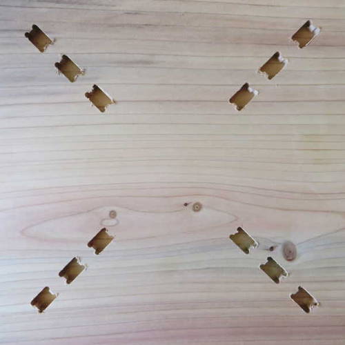
The stand is connected to the table by a press-fit connection, slightly similar to the one I experimented with earlier (see above). I didn't have the chance to first test the connection, because I only had one piece of wood for the table top, but I was pretty sure about this kind of connection. I used Rhino to do the design. The stand has studs, the bottom of the table surface has holes. I didn't use offsets, since the milling machine doesn't take away extra material like the laser cutter does. I added dog bones in the design, 5 mm diameter, so the 5 mm end mill could pas through.
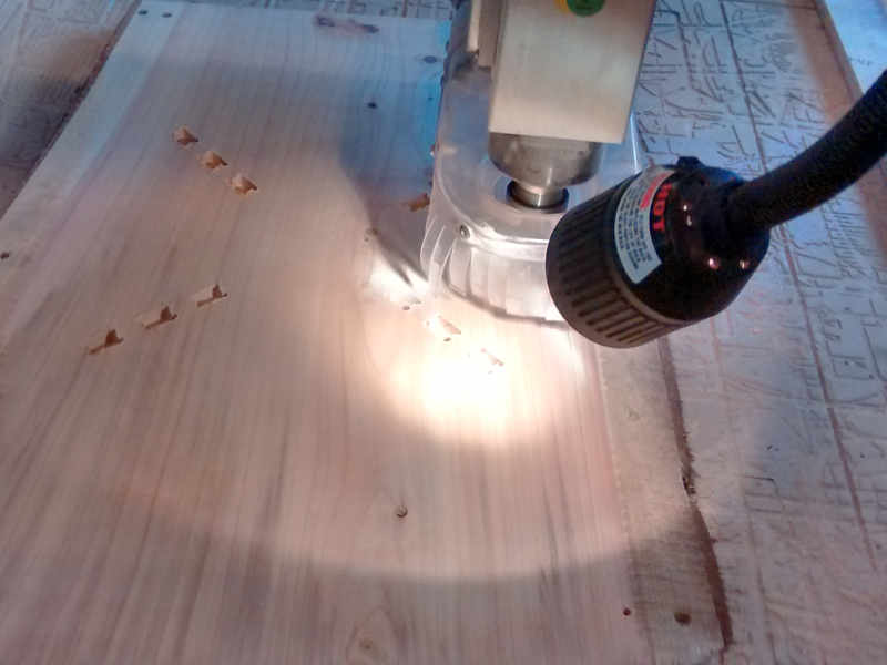
I used a 5 mm flat end mill, pass depth 2.5mm, stepover 2.4 mm, feed rate 100 mm/s, plunge rate 25 mm/s. The stand needed only a profiling job to cut out the shape, I used some tabs to keep it in place.
The holes in the table surface are done by a pocketing job, cut depth 1 cm, the same as the lengths of the studs.
Finally I cut out a the rectangle of the table top, also with the 5 mm end mill and the same settings for the profiling job as the stand (2.5mm, stepover 2.4 mm, feed rate 100 mm/s, plunge rate 25 mm/s)
I didn't have time to do the sanding before I had to leave the lab and doing the documentation, so that still has to be done.
Assembly
The connections fitted well, even without sanding away the rough pieces. The stand and the top stay together well without any glue or screws. The X-stand is not very stable, maybe it is a bit to long and narrow, but if I have some time I could make a new one that will fit to the top when I use the same connection.
Cut files
holes and profile table top
Stand piece A
Stand piece B