 FABRICIO SANTOS
Week 13 - Networking and Communications
Design and build a wired or wireless network connecting at least two processors.
Design the networking circuits
For the last weeks assignmets I designed the input Hello Light and the output Hello Servo introducing a modification in the circuit with four pins bus in order to communicate between the two boards in this Networking assignment.
|
Trying to communicate Hello Light and Hello Servo redesigned boards with each four pin buses. |
But as my Photoresistor board worked properly, the Servo did not...Although I modified the design of the circuit an d I repeat the board, the servo does not work either this week.
 |
 |
 |
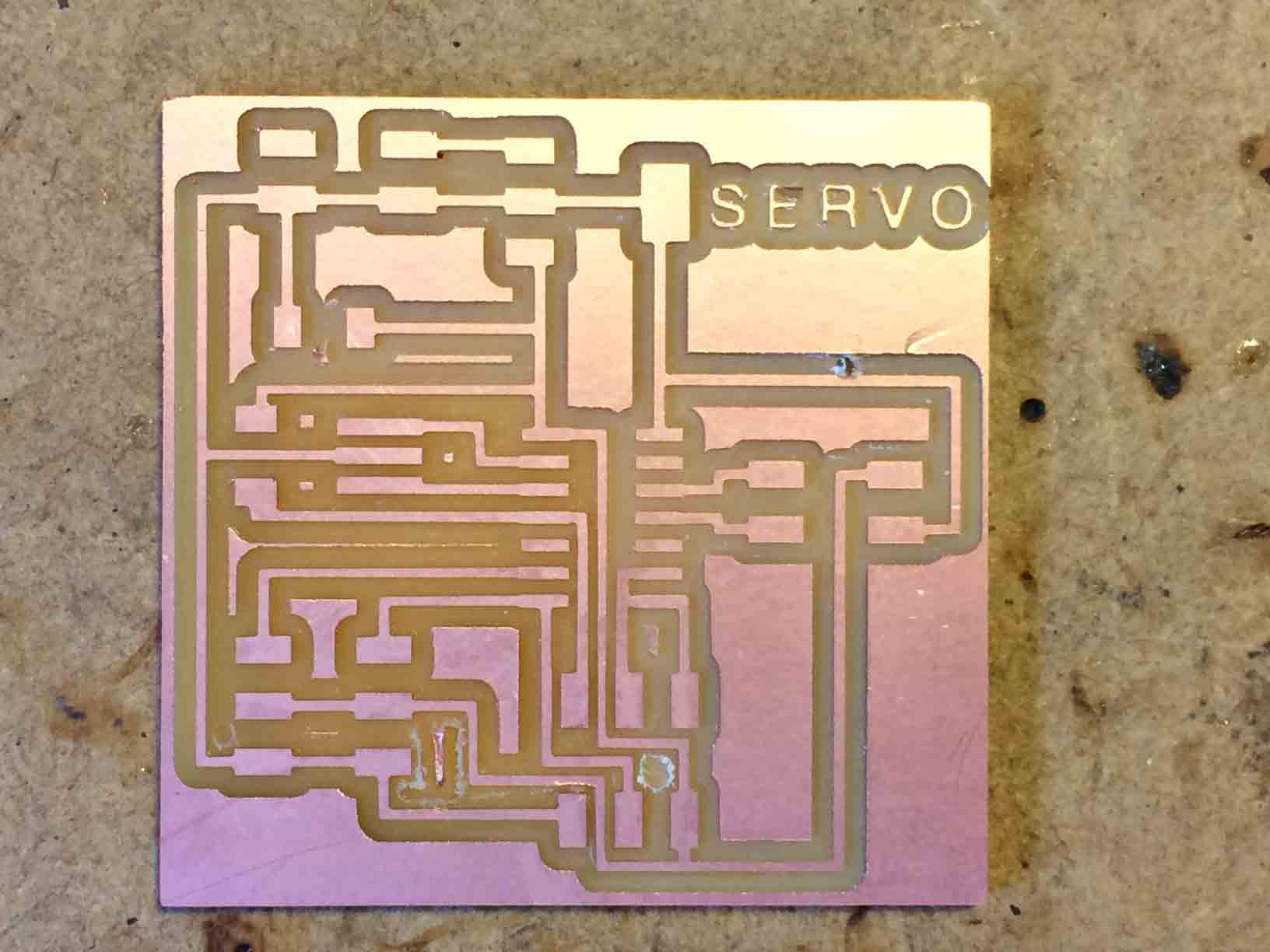
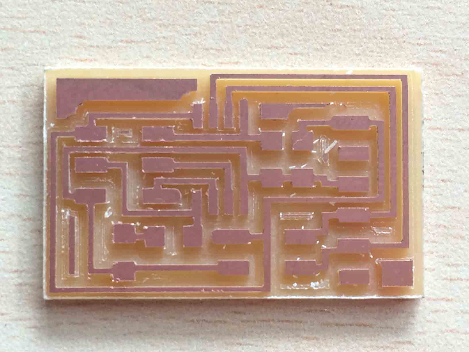
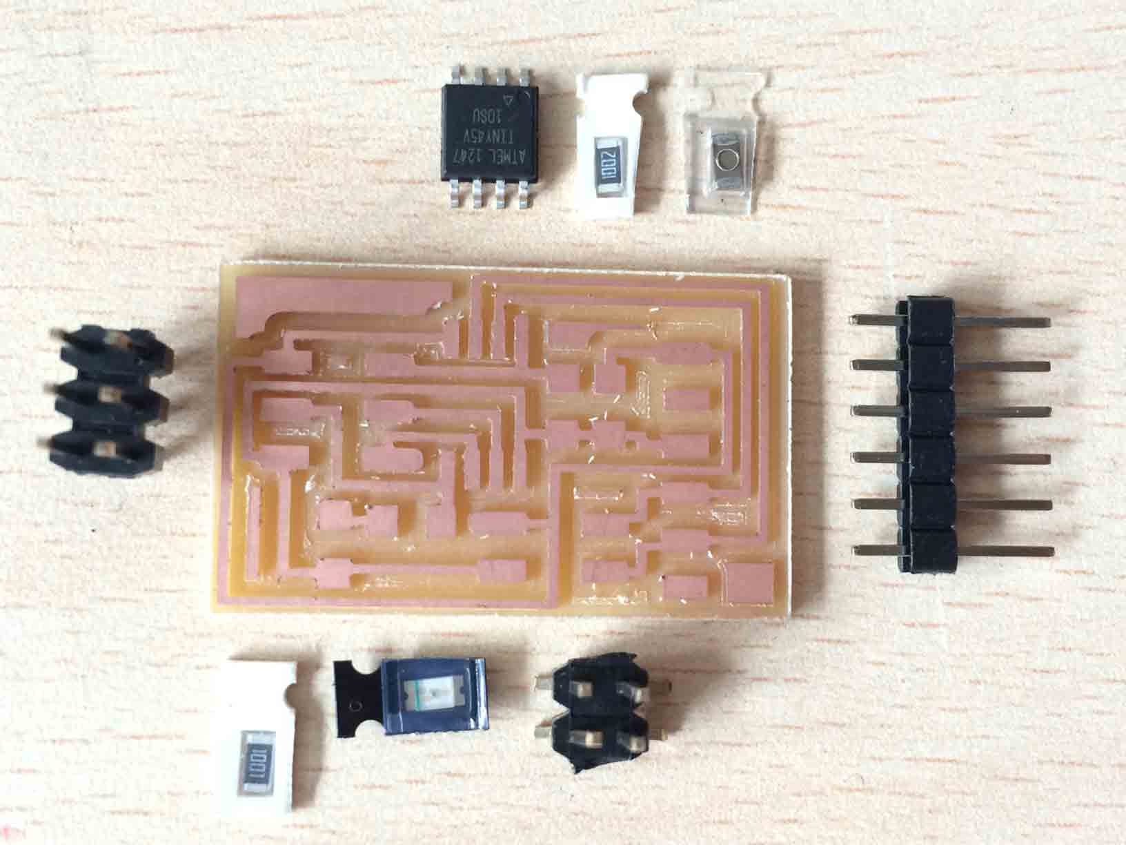
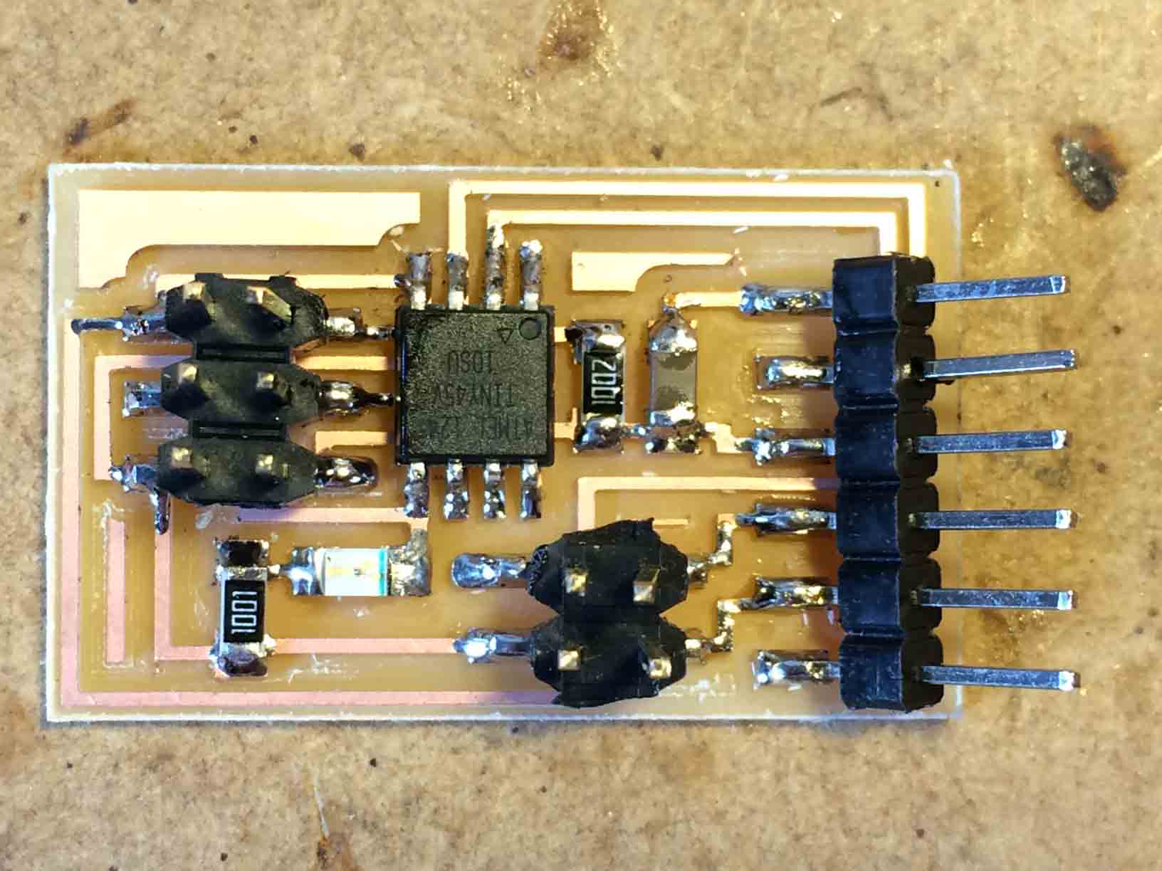
Milling redesigned Servo board. |
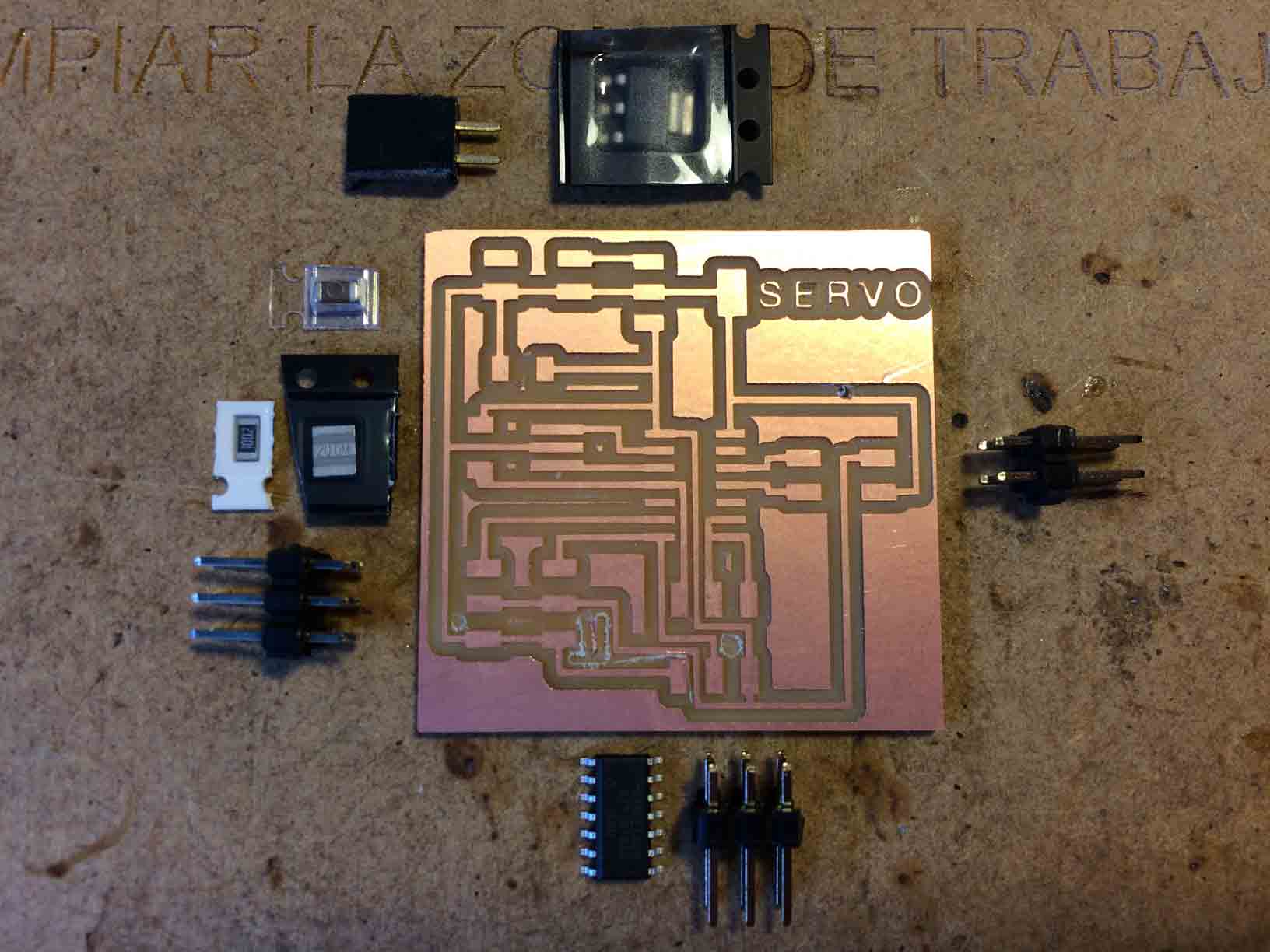
Servo board components. |
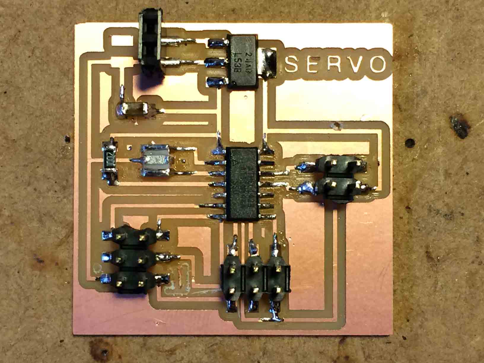
Soldering Servo board. |
So I buid an identical Hello Bridge board as Neil´s design, and I successfully programmed it.
 |
 |
 |
Milled Hello Bridge board. |
Bridge board components. |
Soldered Bridge board. |
So I decided to borrow two Hello Node boards from Nuria´s Fab Lab León in order to program and understand this week assignment. And later I will try to fix my Servo board to complete this assignment correctly.
|
Networking between one Hello Bridge and two Hello Node boards. |
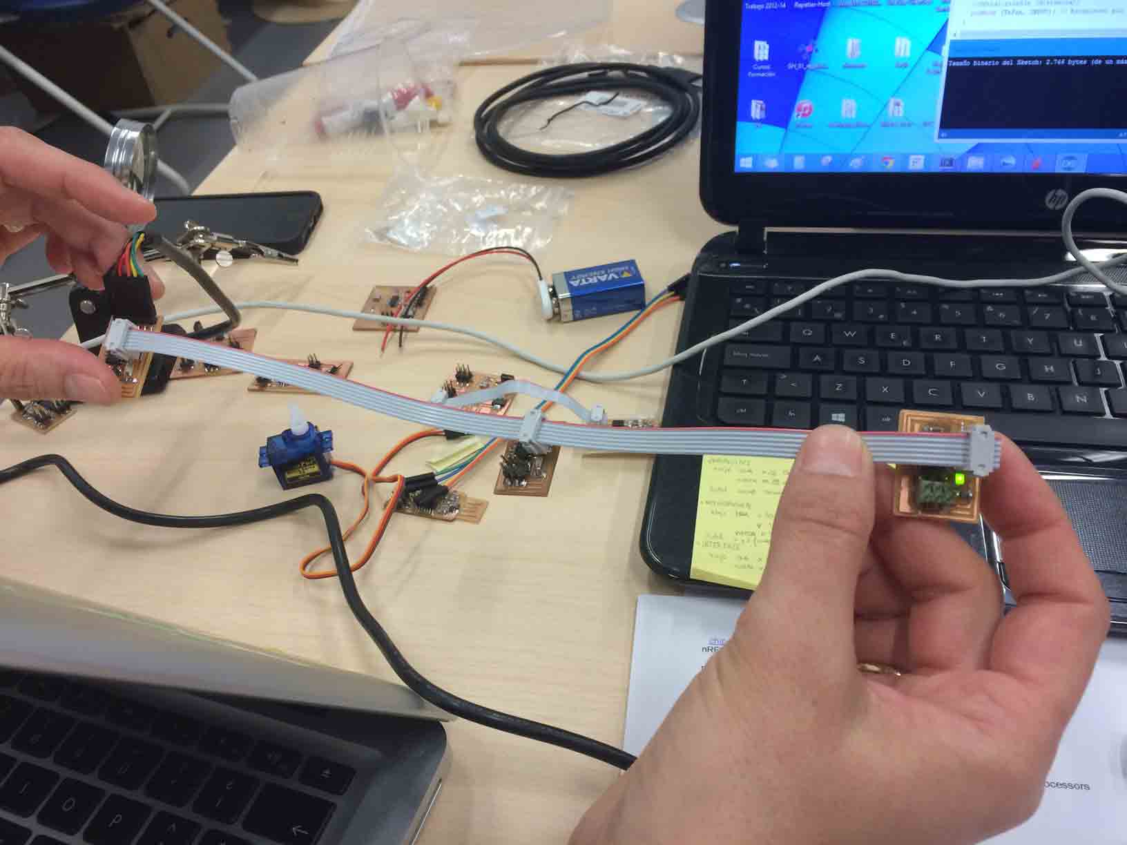
The communication is made by a serial protocol serial.write ( ) that is used to read the values in the Serial Monitor of the Arduino IDE. The node board broadcasts information and the bridge board displays this information.
I used the Arduino IDE to introduce changes and tried to understand how does the communication work:
// ==================== Incluya las librerías necesarias ====================
#include <SoftwareSerial.h>
// Configurar puerto serie.
// PB2 -> pin Tx
// -> Sin pines Rx. Asignado a PB0
#define TxPin 3
#define RxPin 4
SoftwareSerial serie (RxPin, TxPin); // RX, TX
// ======================= Definición de Identificación del nodo ===================== ===
#define NodeID 'a'
// ================== Definición de pines y variables ==================
//#define echoPin 9 // Echo Pin conencted al pin D9 (PB1)
//#define trigPin 10 // Gatillo Pin conectado al pin D10 (PB0)
#define ledPin 0 // LED conectado al pin D7 (PA7)
//#define maximumRange 200 // Alcance máximo necesario
//#define minimumRange 0 // rango mínimo necesario
//int distancia; // Duración utiliza para calcular la distancia
// ================================ Configuración =============== ================
// La rutina de instalación se ejecuta una vez al encender la pizarra:
void setup ()
{
// Configurar puerto serie @ 9600bps
Serial.begin (9600);
// pinMode (trigPin, OUTPUT);
pinMode (ledPin, OUTPUT);
//pinMode (echoPin, INPUT);
pinMode (TxPin, INPUT);
}
// ============================= Bucle principal ================= ============
// La rutina bucle se ejecuta una y otra vez para siempre:
void loop ()
{
Char c = Serial.read ();
digitalWrite (ledPin, LOW);
si (c == NodeID)
{
digitalWrite (ledPin, HIGH);
// distancia = measureDistance ();
pinMode (TxPin, OUTPUT);
Serial.print ("Hola soy el nodo:");
Serial.print (NodeID);
// Serial.print ("Dist:");
//Serial.println (distancia);
pinMode (TxPin, INPUT); // Establecer pin Tx como ipunt. Suelte el canal
}
}
/*
// Funcion a distancia medida con el sensor HC-SR04
// Devuelve la distancia en cm
int measureDistance ()
{
digitalWrite (trigPin, LOW);
delayMicroseconds (2);
digitalWrite (trigPin, HIGH);
delayMicroseconds (10);
digitalWrite (trigPin, LOW);
// Calcular la distancia (en cm) sobre la base de la velocidad del sonido.
distancia = pulseIn (echoPin, ALTA) / 58;
/ * Si (distancia> = maximumRange)
distancia = maximumRange;
si (distancia <= minimumRange)
distancia = minimumRange; * /
regresar a distancia;
}
*/
To sum up these were my conclusions:
- if we load to two nodes the same program it will fail: bridge + node 1 + node 1 = error
- we use the RS-232 Serial Data Standards for communication protocol
- we used Arduino IDE to visualize the shipping information and its response.
- on Neil´s Node board we conected input Tx in PB3 / output LED in PB0 and Rx in PB4 (PCINT4)
Design the wired networking between a photoresistor and a servo board
I continued looking for fix the problems on my Servo board and I solved it (see week 11: output devices).
As I said for the last weeks assignmets I designed the input Hello Light and the output Hello Servo introducing a modification in the circuit with four pins bus in order to communicate between the two boards in this Networking assignment.
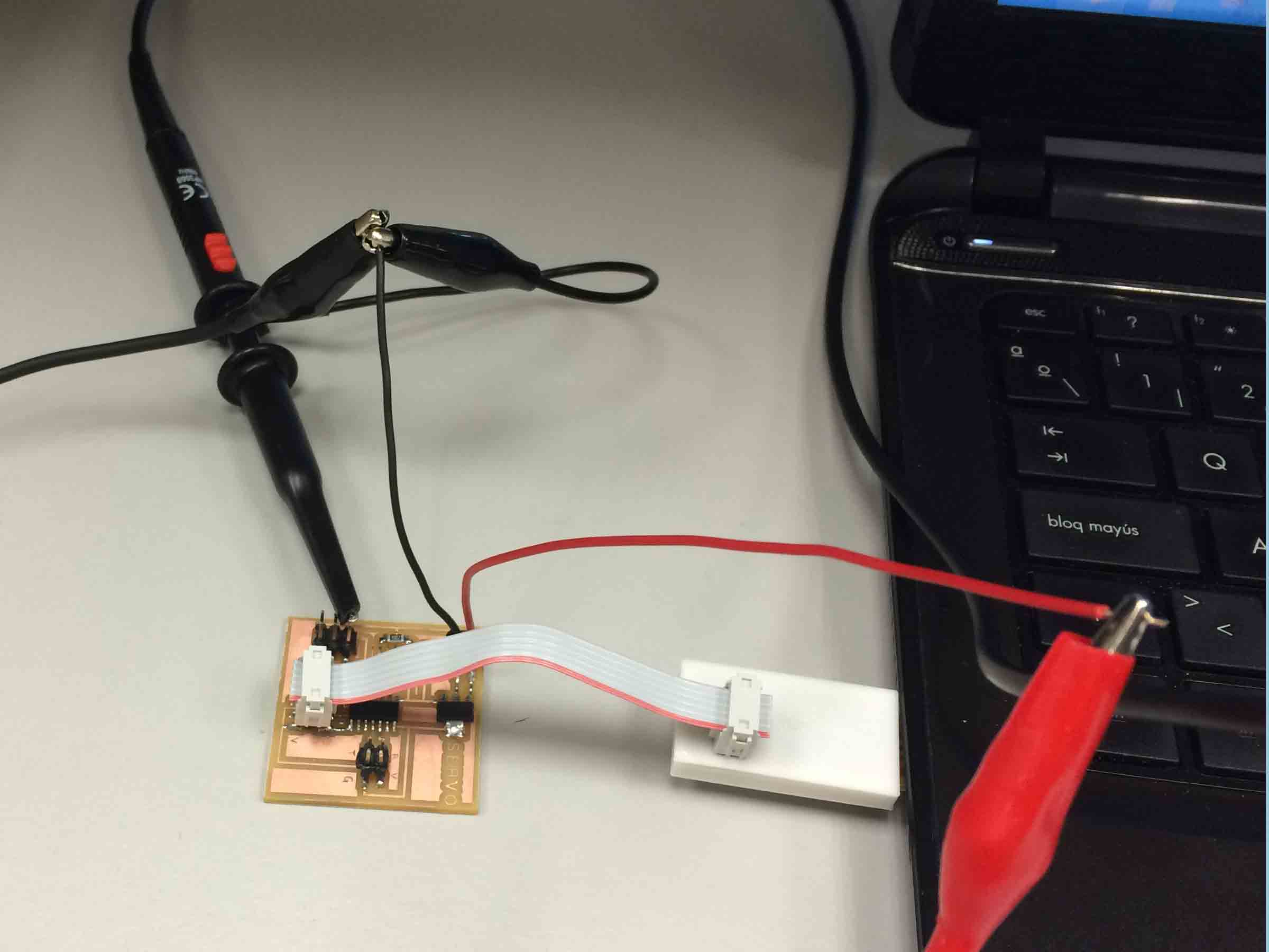
Taking into account that I changed the order of the Tx and Rx pins when I redesigned the Hello Light board I connected them between the two boards.
|
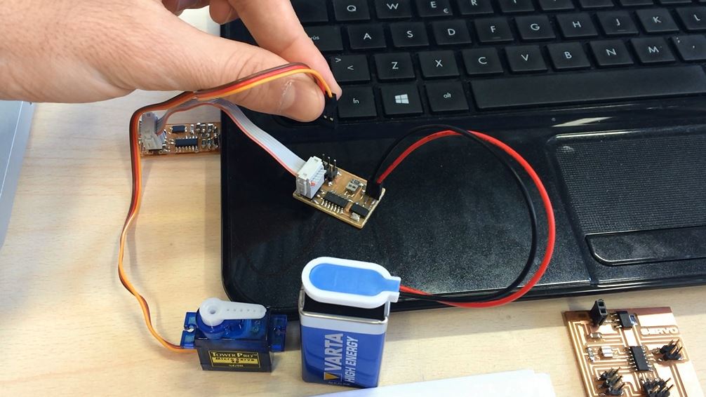
Networking between one Hello Light and two Hello Servo modified boards. |
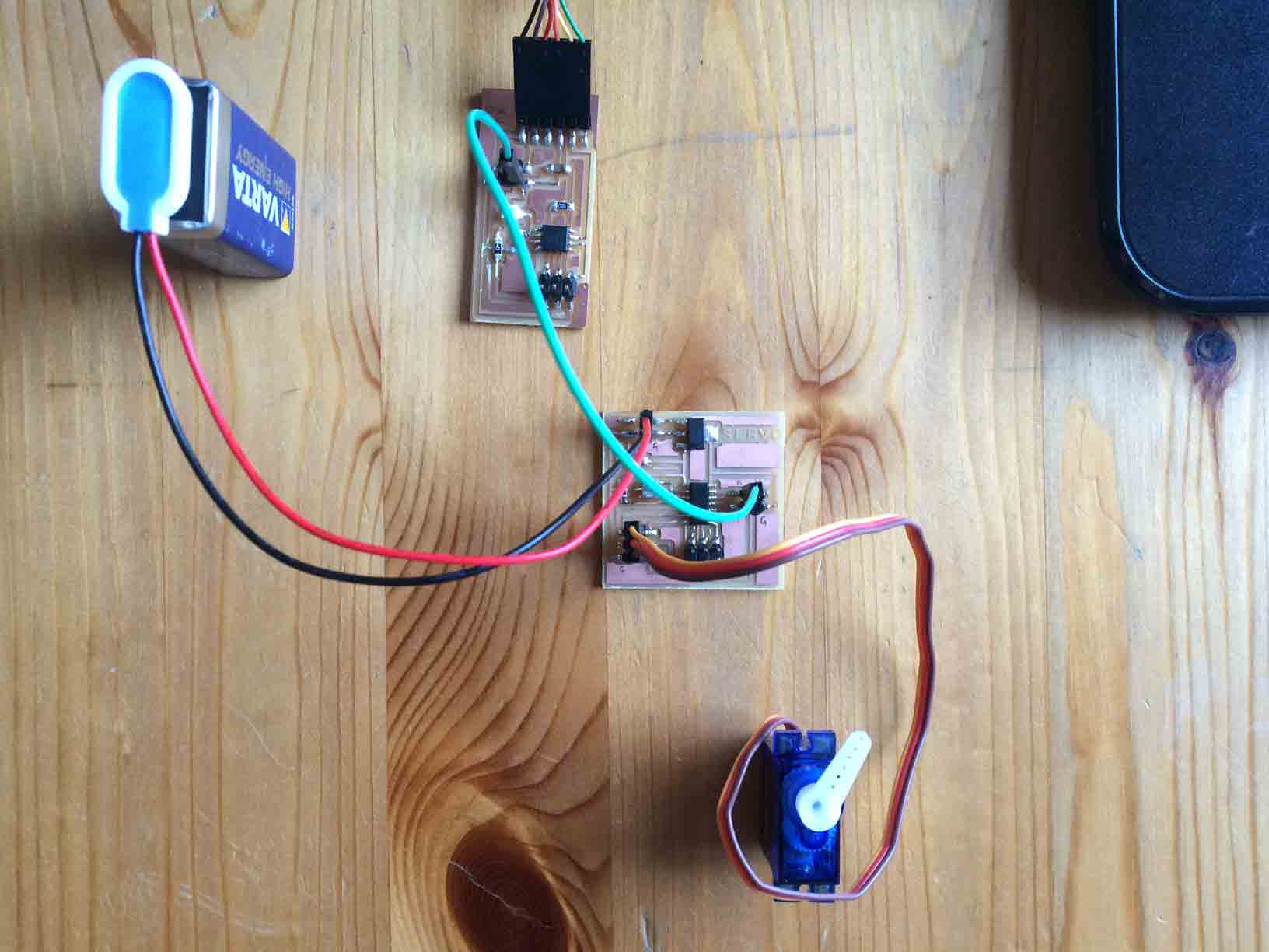
As the boards properly work separately, when I try to communicate between them the problems start.
I will try to fix it because it would be the essence of my final project in order to accionate the déployé dome.
This is the Arduino Example AnalogInOutSerial code I used to communicate them:
/*
Analog input, analog output, serial output
Reads an analog input pin, maps the result to a range from 0 to 255
and uses the result to set the pulsewidth modulation (PWM) of an output pin.
Also prints the results to the serial monitor.
The circuit:
* potentiometer connected to analog pin 0.
Center pin of the potentiometer goes to the analog pin.
side pins of the potentiometer go to +5V and ground
* LED connected from digital pin 9 to ground
created 29 Dec. 2008
modified 9 Apr 2012
by Tom Igoe
This example code is in the public domain.
*/
// These constants won't change. They're used to give names
// to the pins used:
const int analogInPin = A0; // Analog input pin that the potentiometer is attached to
const int analogOutPin = 9; // Analog output pin that the LED is attached to
int sensorValue = 0; // value read from the pot
int outputValue = 0; // value output to the PWM (analog out)
void setup() {
// initialize serial communications at 9600 bps:
Serial.begin(9600);
}
void loop() {
// read the analog in value:
sensorValue = analogRead(analogInPin);
// map it to the range of the analog out:
outputValue = map(sensorValue, 0, 1023, 0, 255);
// change the analog out value:
analogWrite(analogOutPin, outputValue);
// print the results to the serial monitor:
Serial.print("sensor = " );
Serial.print(sensorValue);
Serial.print("\t output = ");
Serial.println(outputValue);
// wait 2 milliseconds before the next loop
// for the analog-to-digital converter to settle
// after the last reading:
delay(2);
}
Debugging process to communicate Hello Light and Hello Servo boards
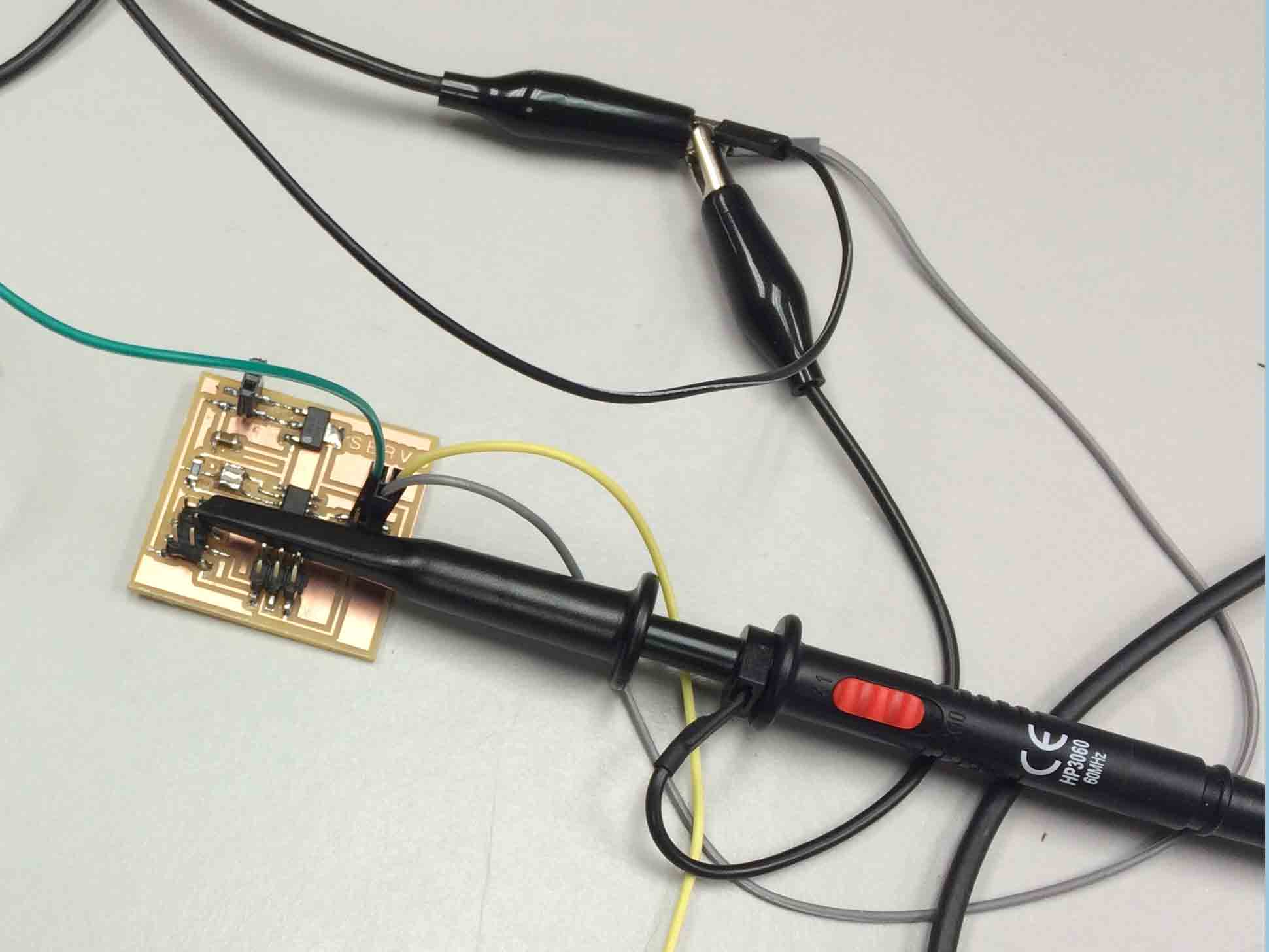
Helped by a computer engineer from my university and ussing an oscilloscopeI I measured the signal emitted by the Hello Light board. And I realized two problems with my Hello Light and Hello Servo boards:
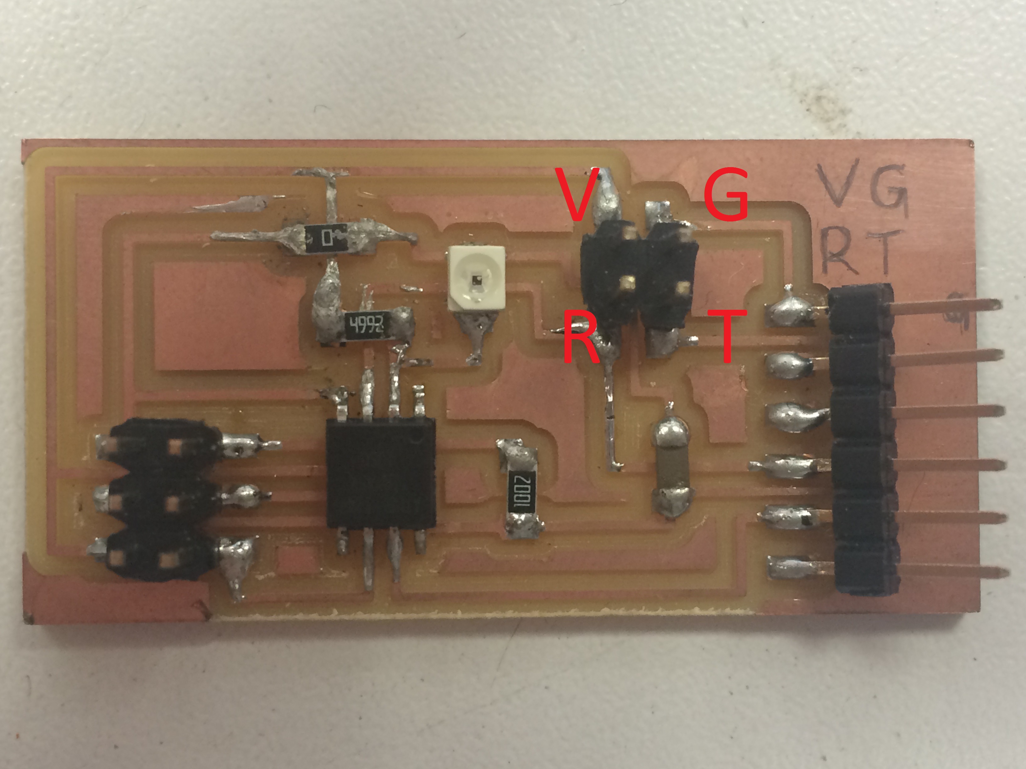
1 On the Hello Light board the pins were changed when I designed it...
So when I tried to connect them between the Tx of the Light and the Rx of the Servo, I were connecting two Rx actually...
|
This is the real pin connection of my Hello Light board. |
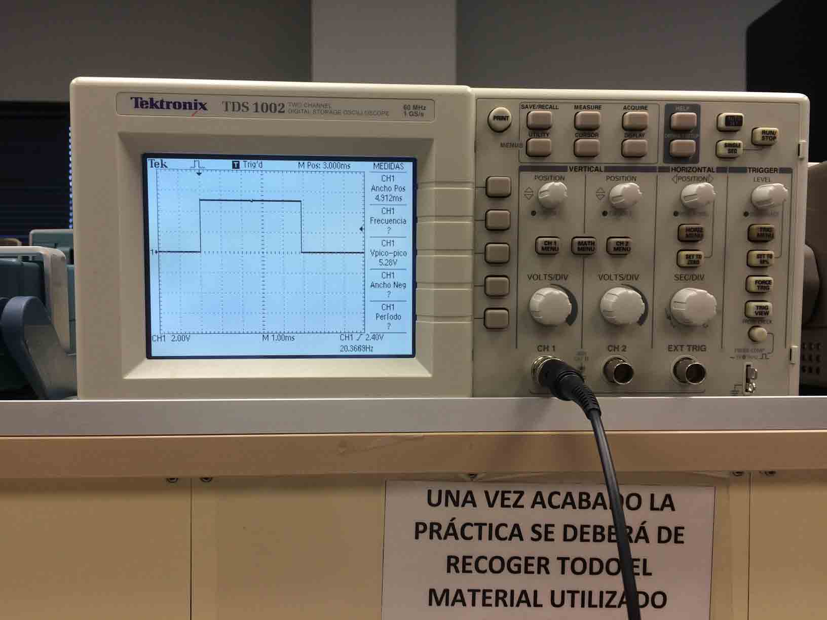
2 I load the Blink example program with the Arduino IDE and I meassure the pulse emitted by the servo that in theory was supposed to be 1 second but watching the oscilloscope it last 10 seconds...Wich means that there is a problem with the resonator I soldered on the Servo board, it was not a 20MHz resonator as I thought, it was a 1MHz one.
|
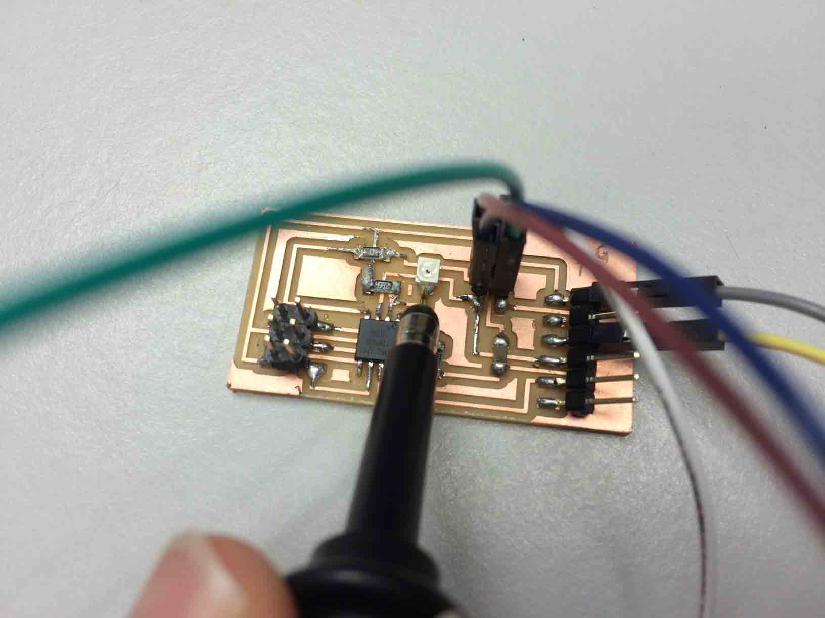
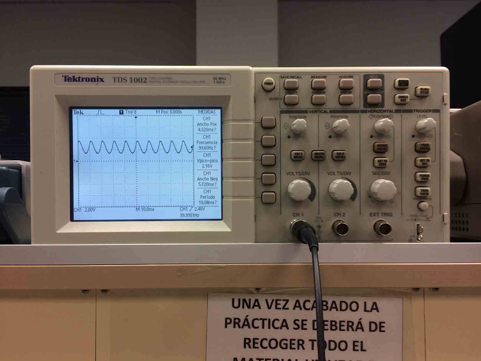 |
Reading the analog signal from the phototransistor. |
An analog signal of the photoresistor on the oscilloscope. |
|
|
Reading the digital signal from the servo. |
An analog signal of the servo on the oscilloscope. |
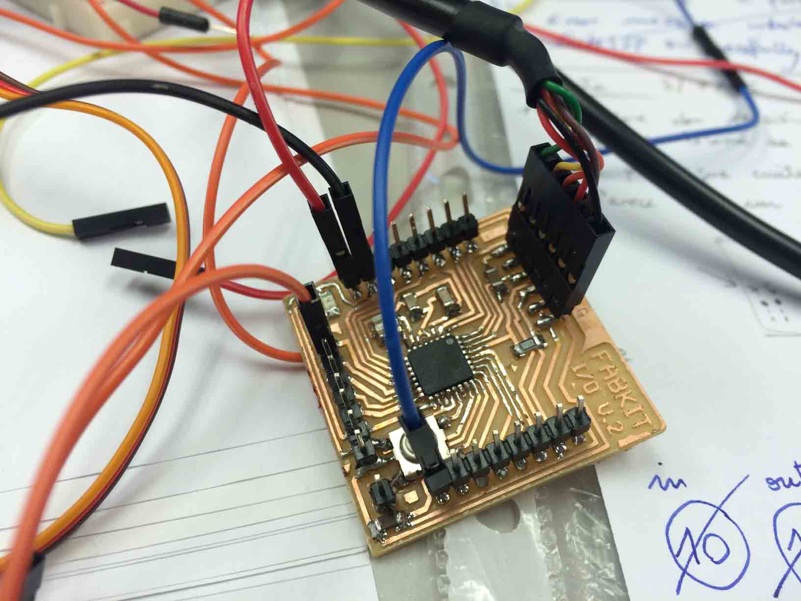
So I loaded the Sweep Example program with the Arduino IDE and I read the signal from three diferent boards with diferent resonators in order to check their speeds: my Hello Servo (1MHz), an Arduino Leonardo (16MHz) and my FabKit i/o 0.2 (16MHz).
|
|
 |
Reading the signal from my Hello Servo. |
Reading the signal from an Arduino Leonardo. |
Reading the signal from my FabKit i/o 0.2. |
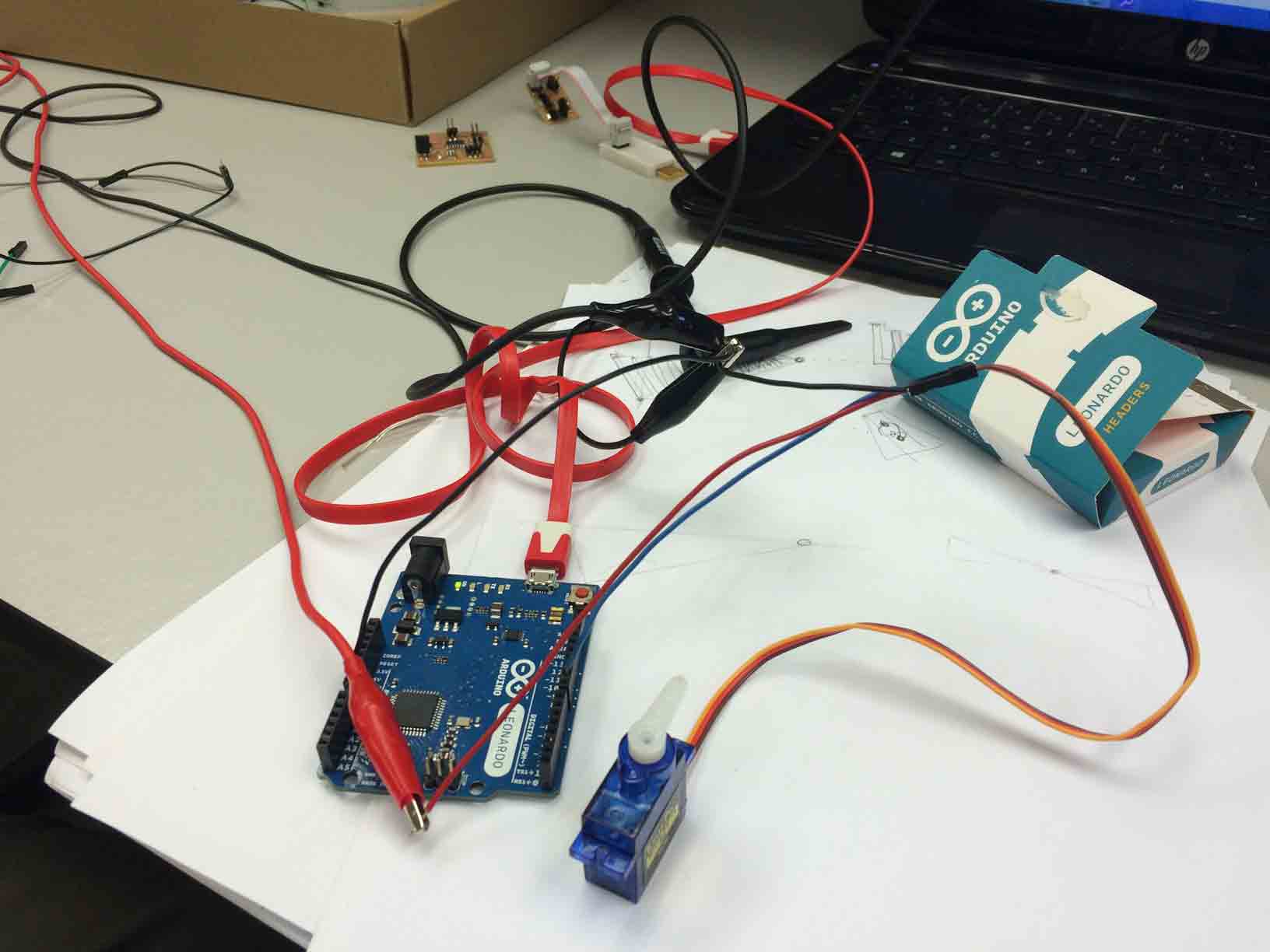
The Sweep program properly worked in Leonardo and FabKit but did not in my Servo board. In conclusion the servo component was not able to work with a so lower signal, it needs more than 1 MHz resonator.
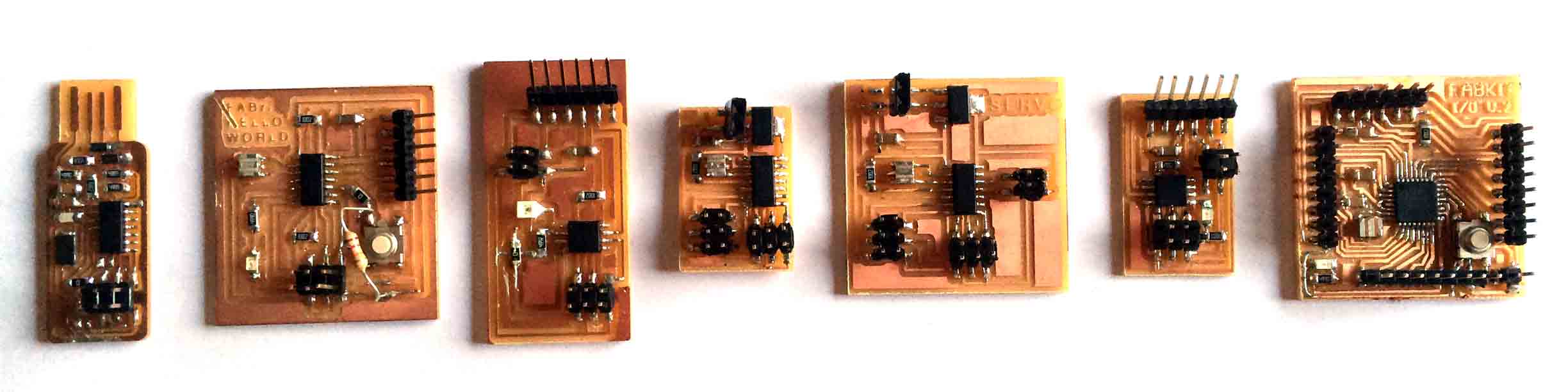
|
This is my successful electronic production: FabISP, Hello World, Hello Light, Hello Servo x2, Hello Bridge and FabKit i/o 0.2. |
But at least I managed to communicate my Hello Light board with a servo connected on my FabKit board (visit my Final Project assignment).
Communication between Light and Servo from Fabricio Santos on Vimeo.