 FABRICIO SANTOS
Final Project
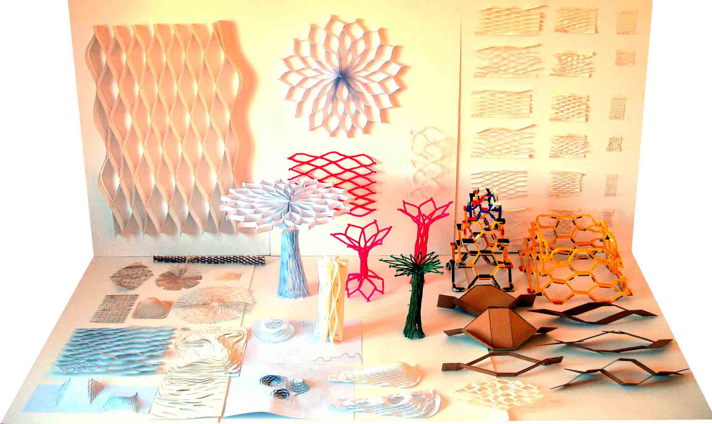
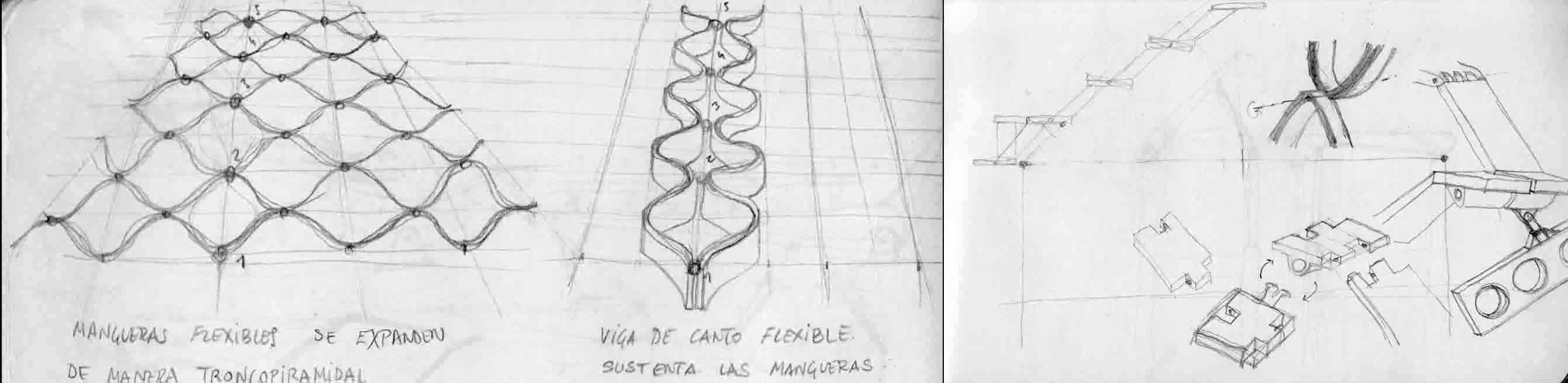
The project begins from a personal research based on déployé domes made up from stretchable meshes.
|
Picture of some hand made and laser cutting déployé prototypes. |
This project requires to include as many abilities learned in the weekly assignments as possible.
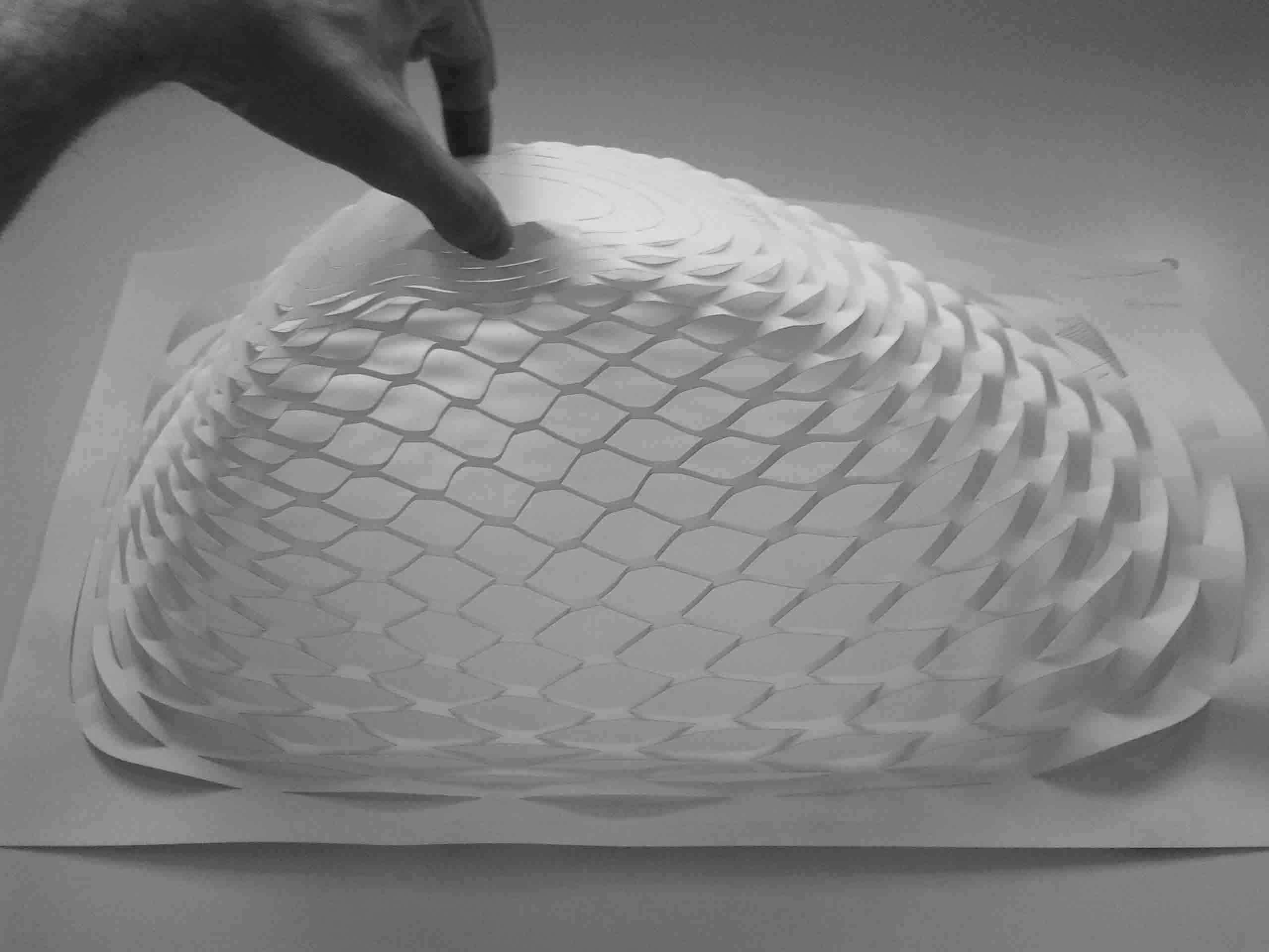
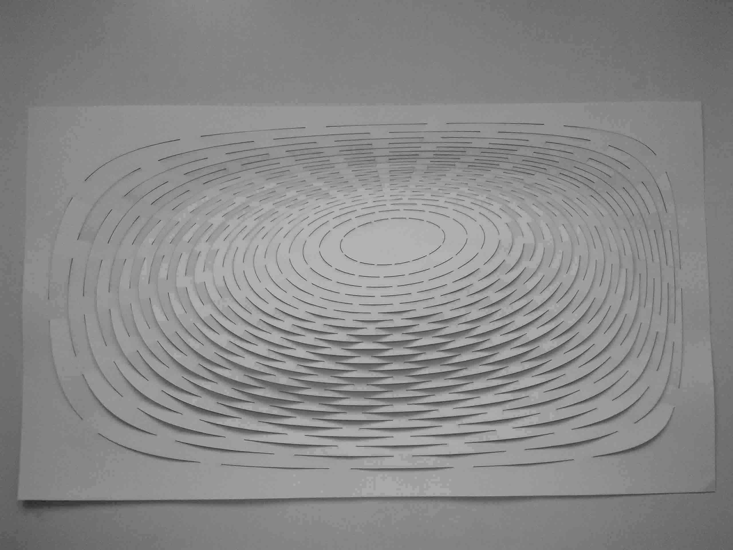
I am interested in building déployé domes and control their movement through electronic devices. So that a flat surface made by concentrically articulated pieces becomes a dome made by hinged parts when stretched upward.
|
Déployé stretchable mesh dome made of paper. Lifted and flattened. |
The control of this movement depends on the construction of the mechanism which activates the déployé dome:
The first way to lift the dome would be to use some mechanism that would push it up.
This would require the design of articulated pieces of the déployé dome on one side and the actuator mechanism on the other.
This special pieces would be manufactured in series and I think the molding would be the best way to get them.
|
Sketch of one way of lifting the dome. |
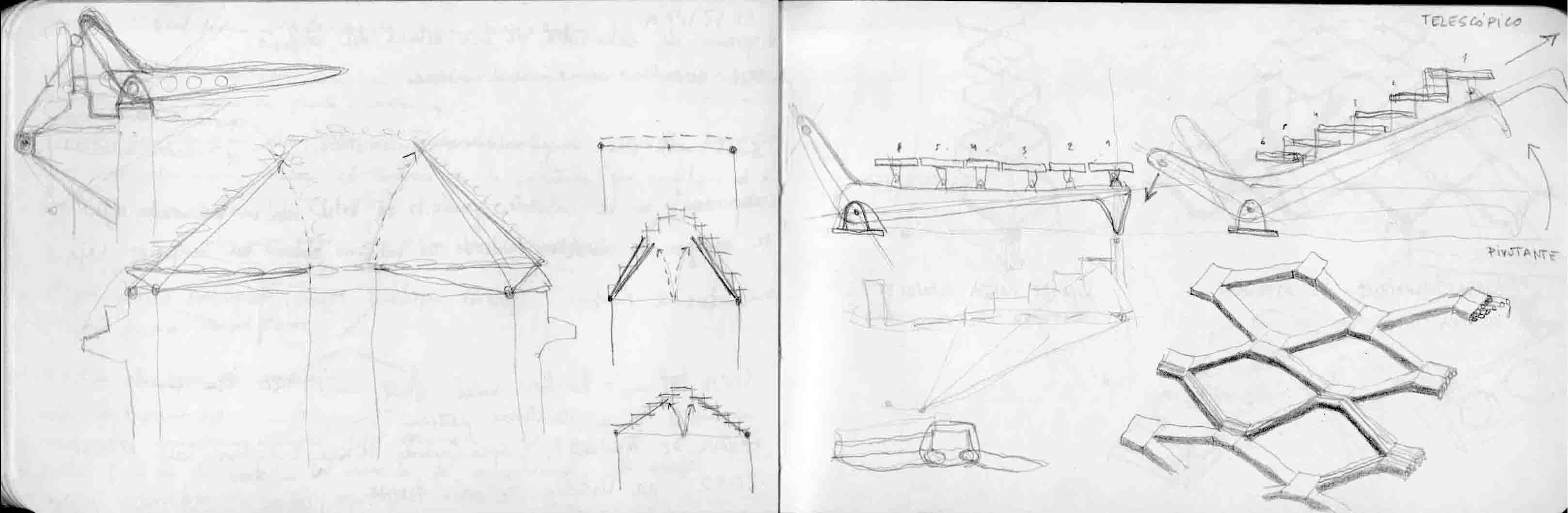
Another way could be build it with shape memory materials such as Nitinol to receive stimulation to actuate the dome up or down.
This idea appeals to me more because both dome and actuator would be the same thing.
Besides this material is being used in the medical field and I would like to investigate it.
|
Sketch of another way of lifting the dome. |
Also the design of the electronic actuator circuit is something that I know nothing about it today, so it will be a great challenge for me to solve it.
DEVELOPEMENT OF THE FINAL PROJECT
Building the pieces of the déployé dome
|
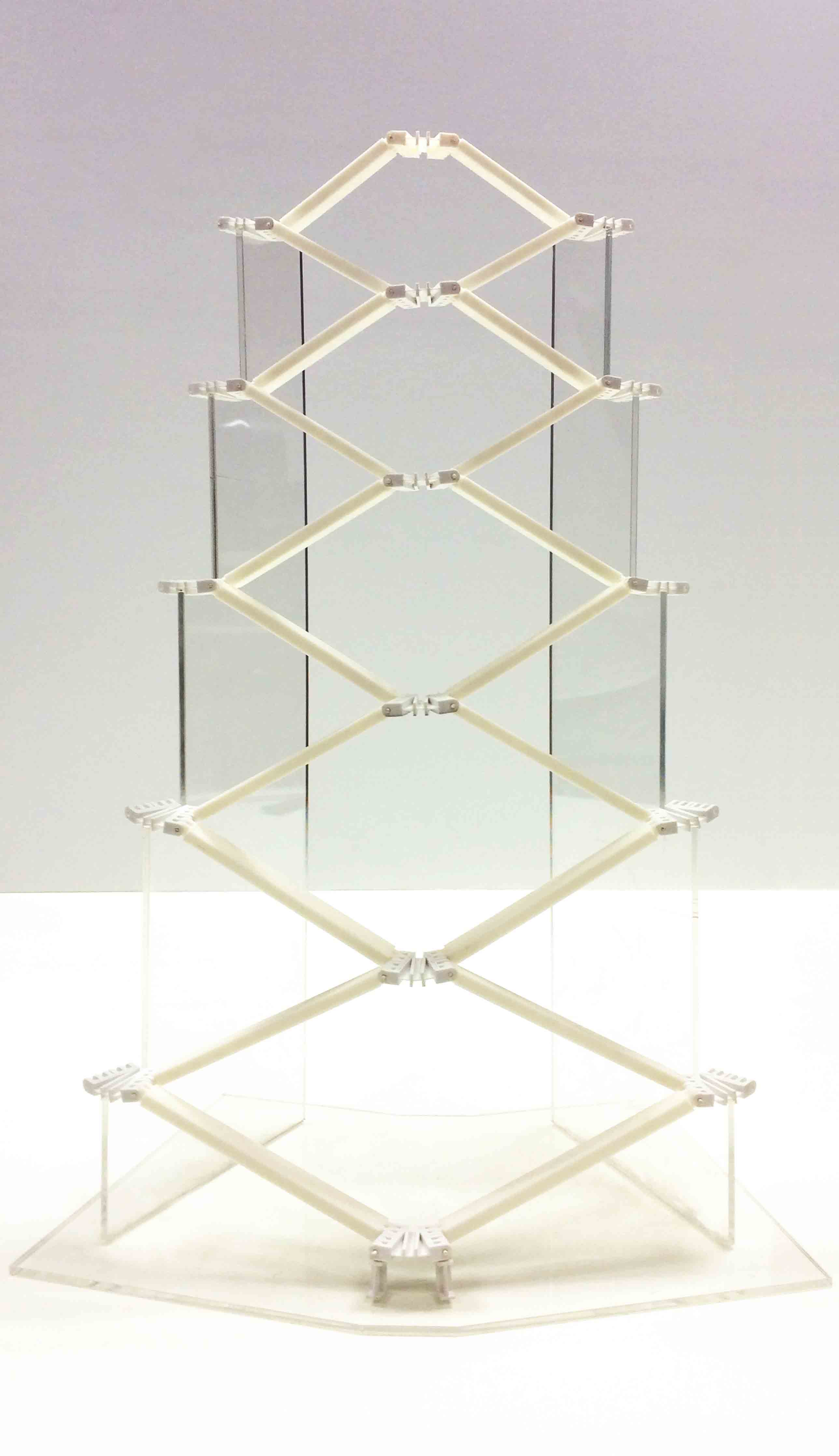 |
One sector of the déployé dome, flattened and lifted. |
|
I decided to abandone the idea of using Nitinol because of the scale of the project and I decided to work with small plastic pieces. So I started building a sector in order to see how does it work.
|
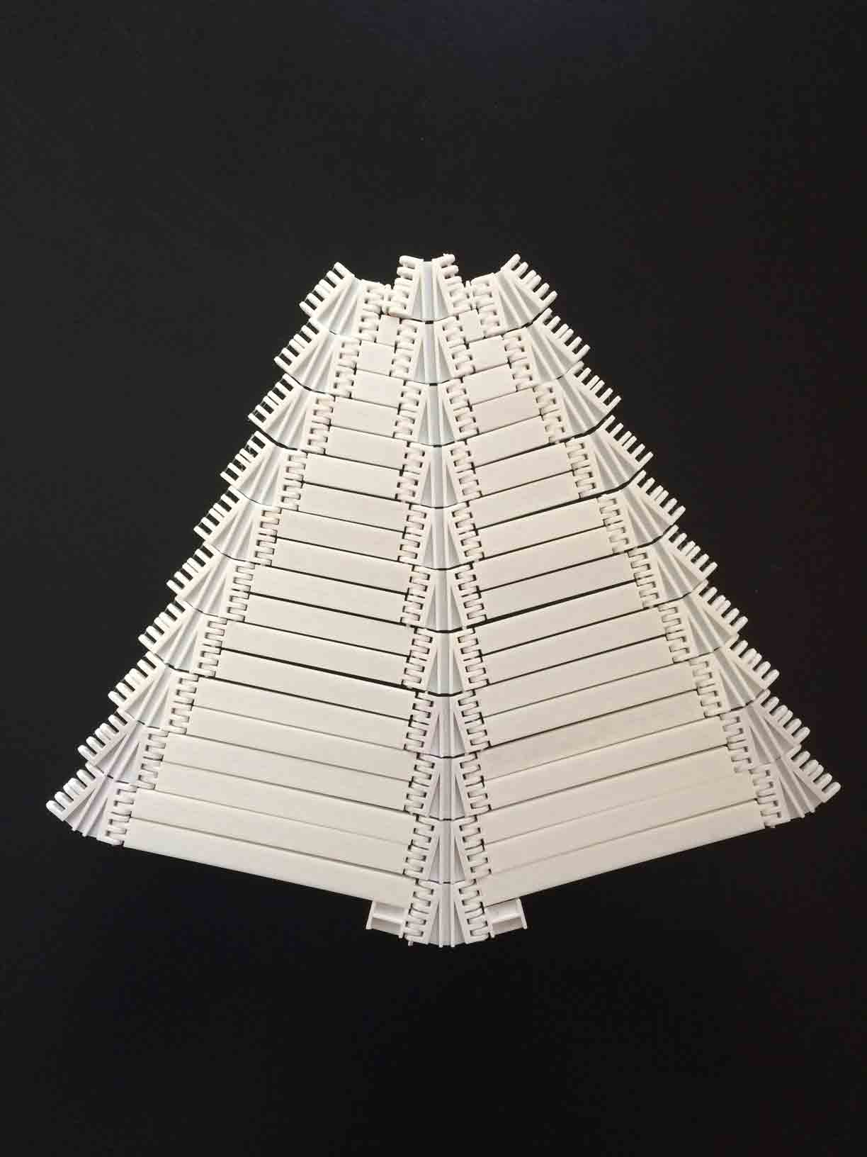
3D printing dome bars |
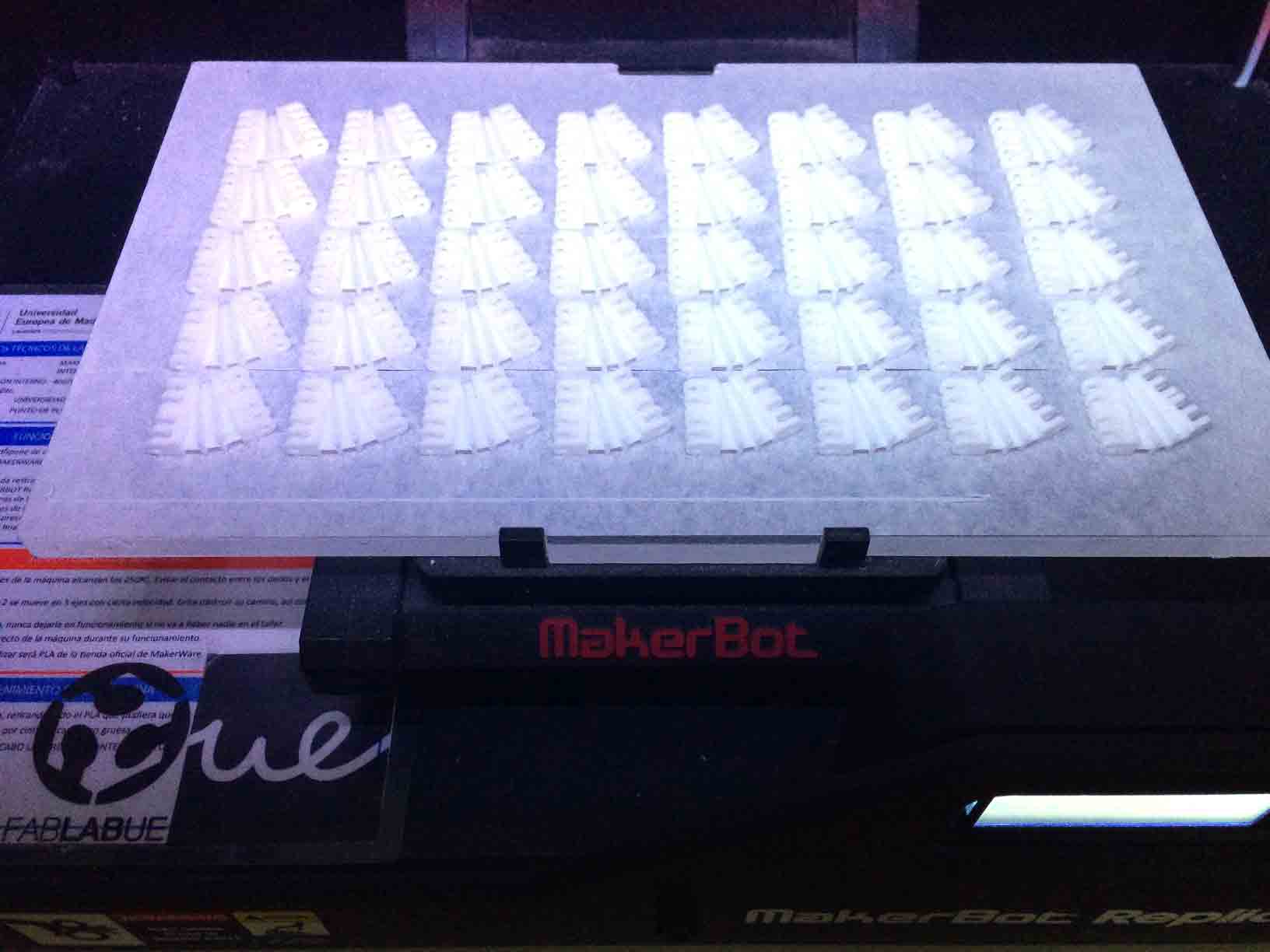
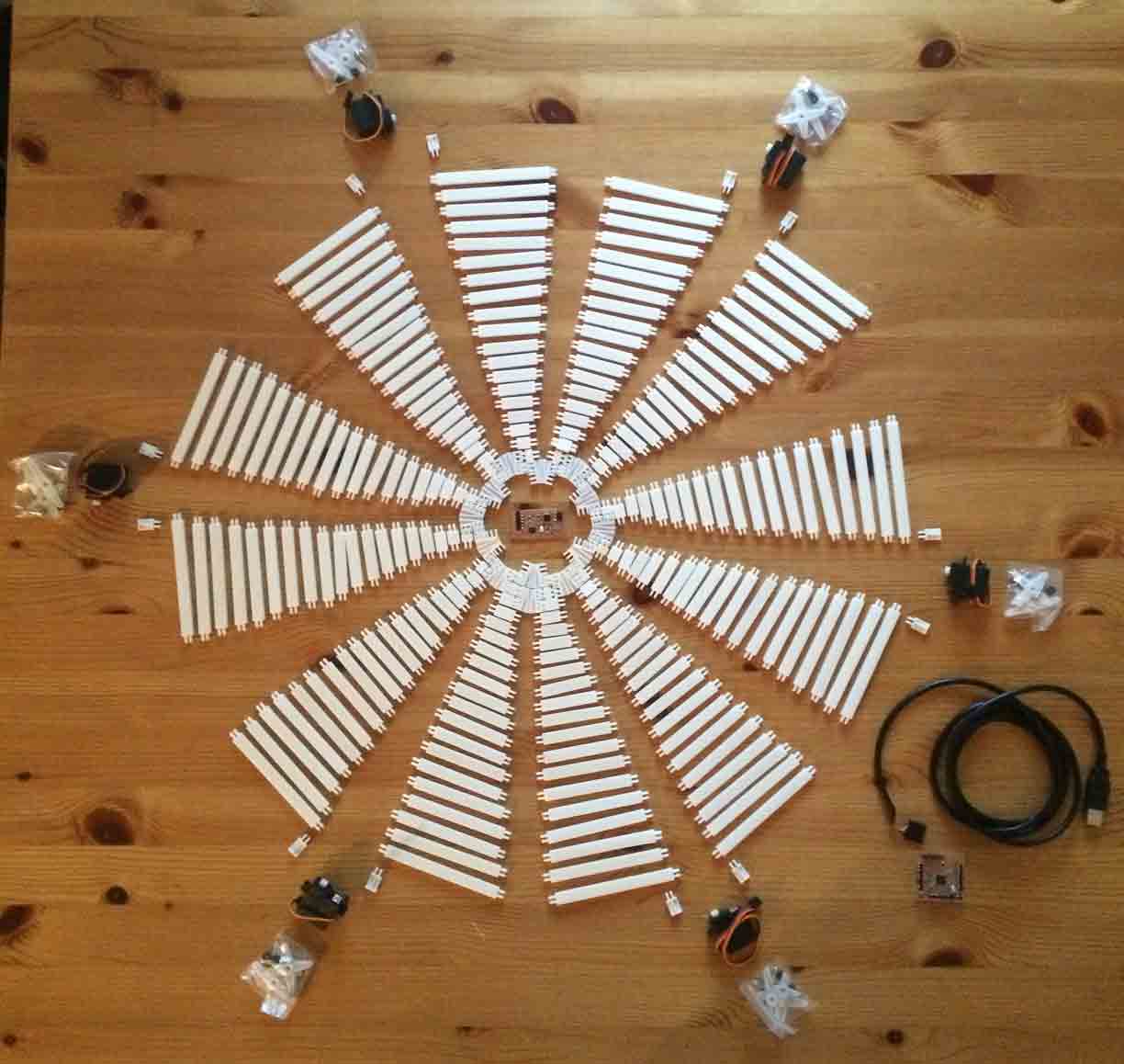
Then I 3D printing 240 bars and 120 hinges that will compose the skin of the déployé dome made by PLA plastic pieces.
|
3D printing dome bars |
The dome is fixed by 240 plastic bolts passing throgh their holes.
|
 |
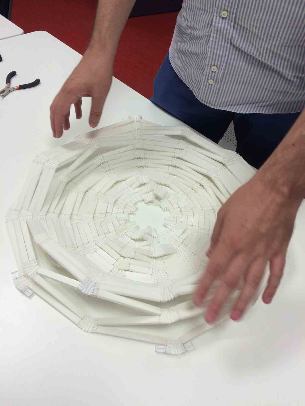
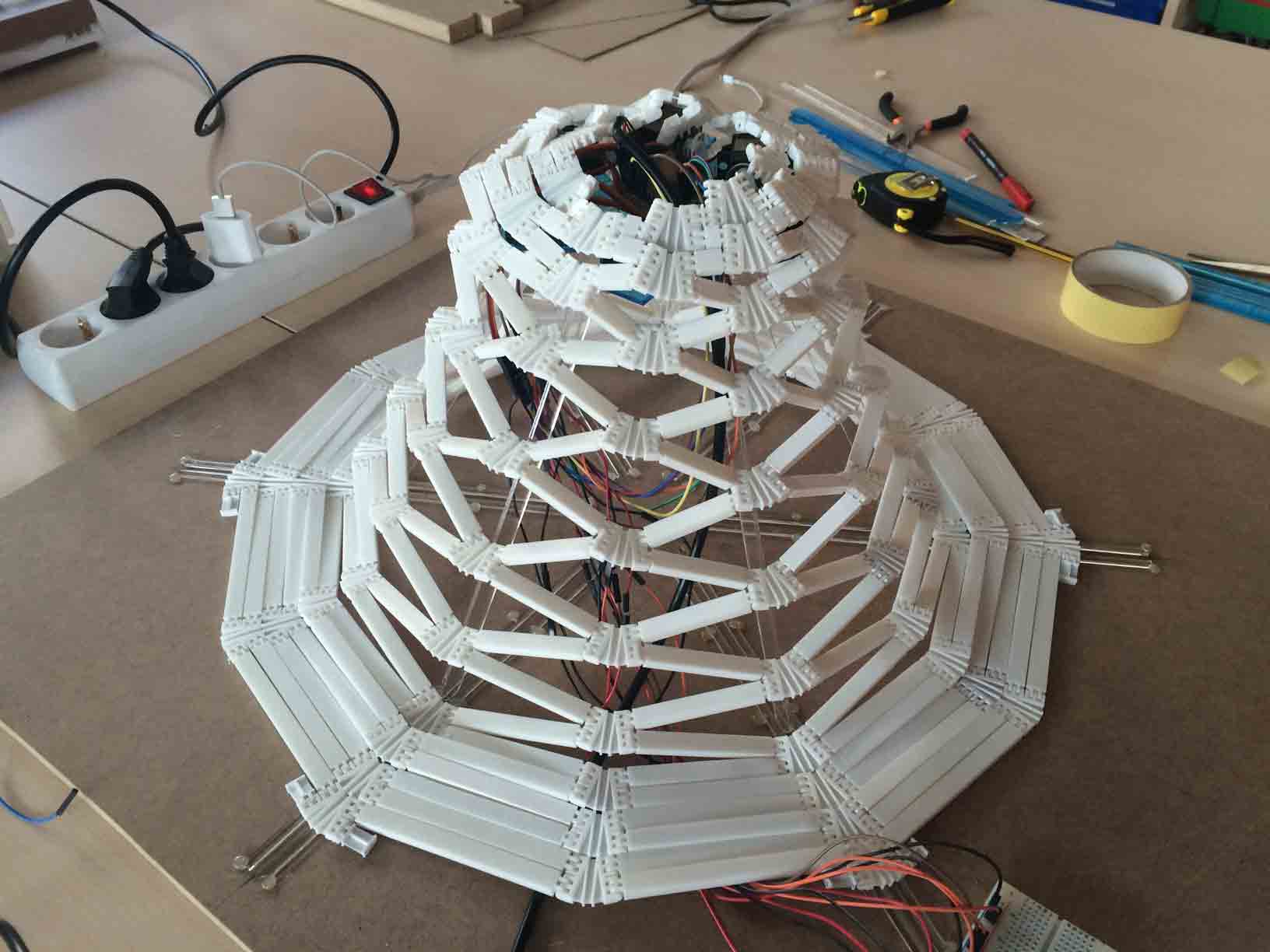
Building the déployé dome. |
Polishing the edges of the bolts so that the dome properly fits. |
|
 |
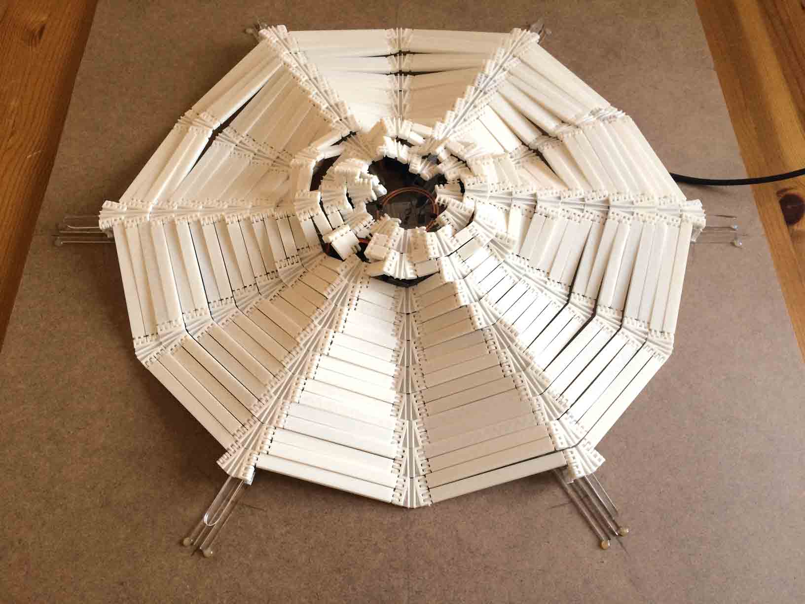
Flattened déployé dome. |
Lifted déployé dome. |
Designing the structure that actuates the dome
|
Lasser cutting file for the structure. |
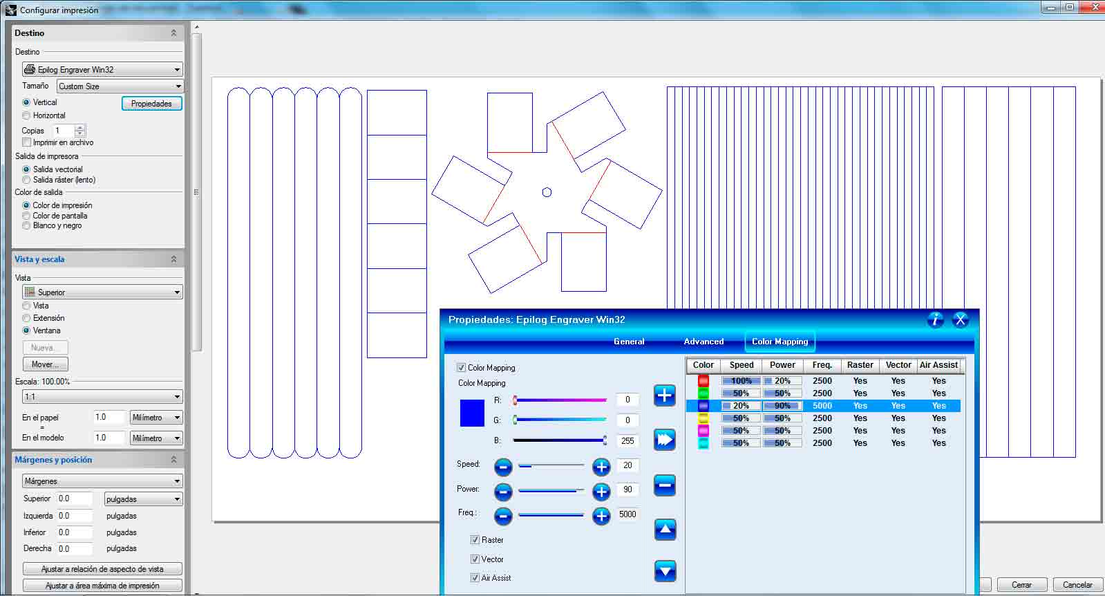
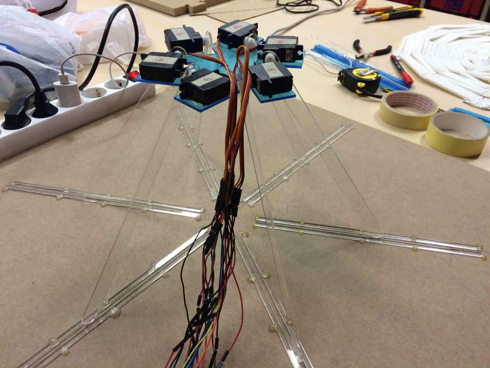
For the structure that actuates the dome I decided to build a kind of compass componed by six arms mounted on a swastika shaped base that allows rotation of the blades by designing a slot at the key of the dome. I made it in laser cutting transparent acrylic of 2 mm thickness.
|
 |
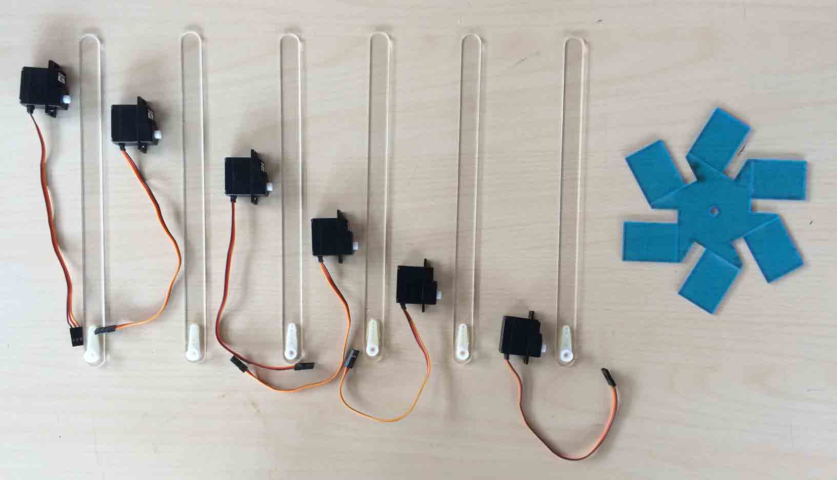
Decomposed acrylic structure for the servos, blades and swastika crown. |
Blades mounted on the swastica crown. |
|
 |
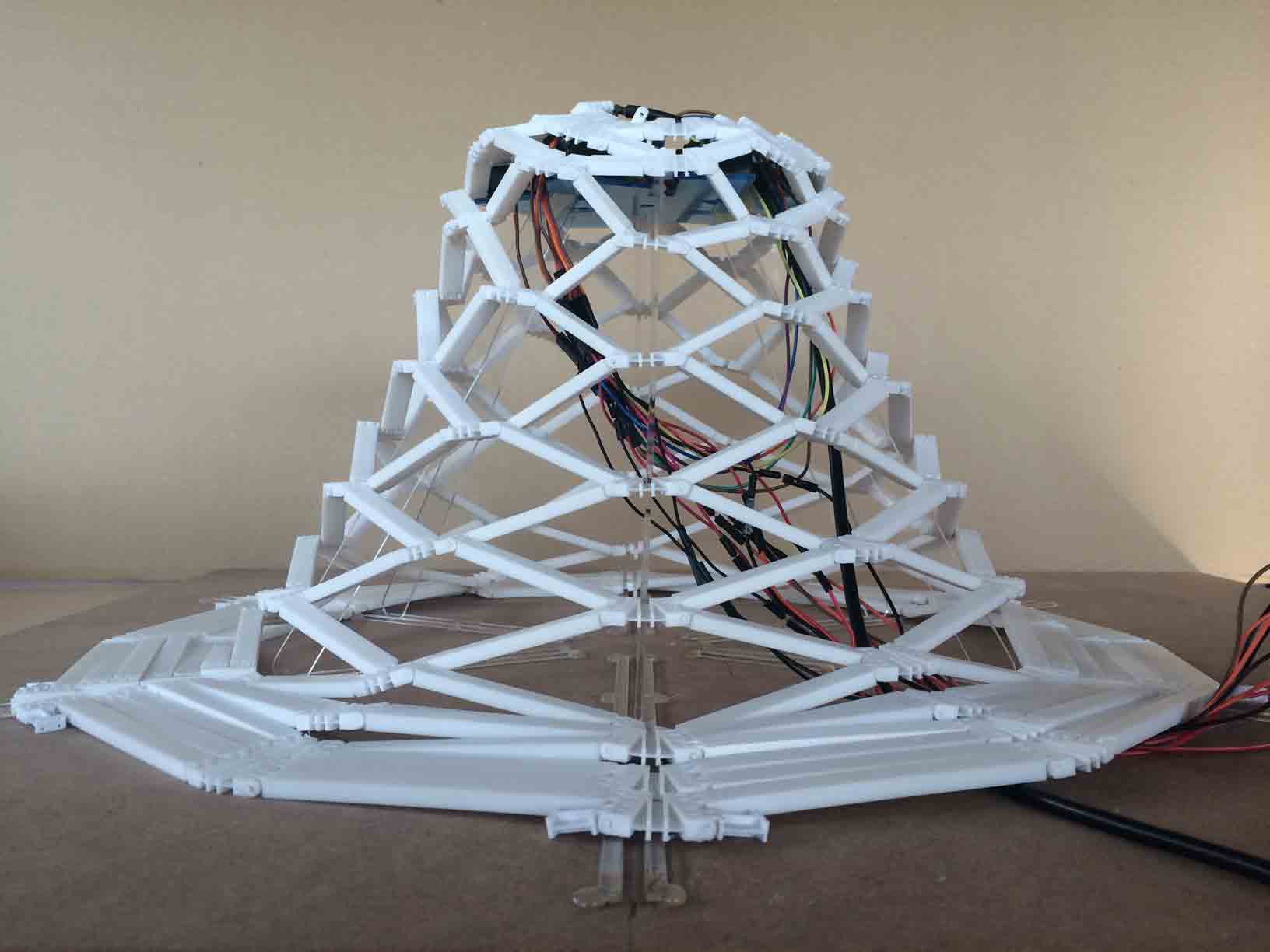
Lifted compass structure. |
Lifted déployé dome with structure below. |
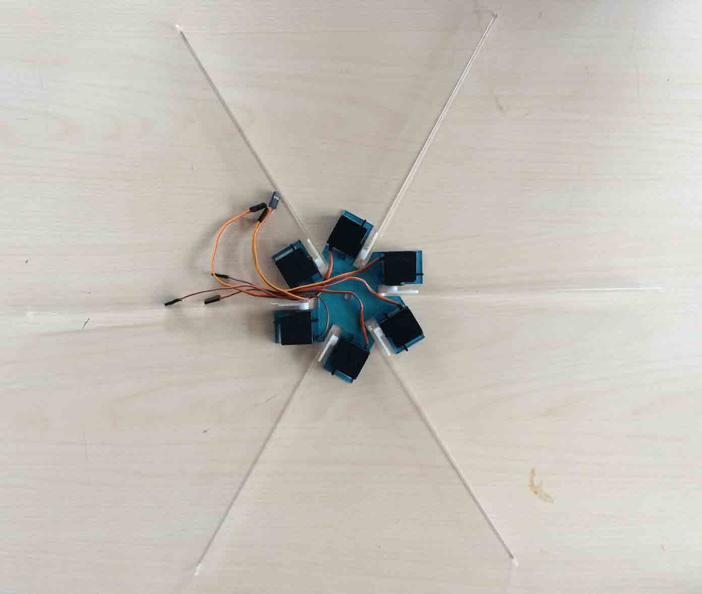
The déployé knots geometry was designed so that the blades slide down them leaning on the guides of the base while the bars were rotating on the opposite direction. And that is what allows the entire déployé dome to stretch and shrink.
The crown of the blades has a hole in the center that allows the phototransistor to pass throgh and read the intensity of the light on the domes key.
|
 |
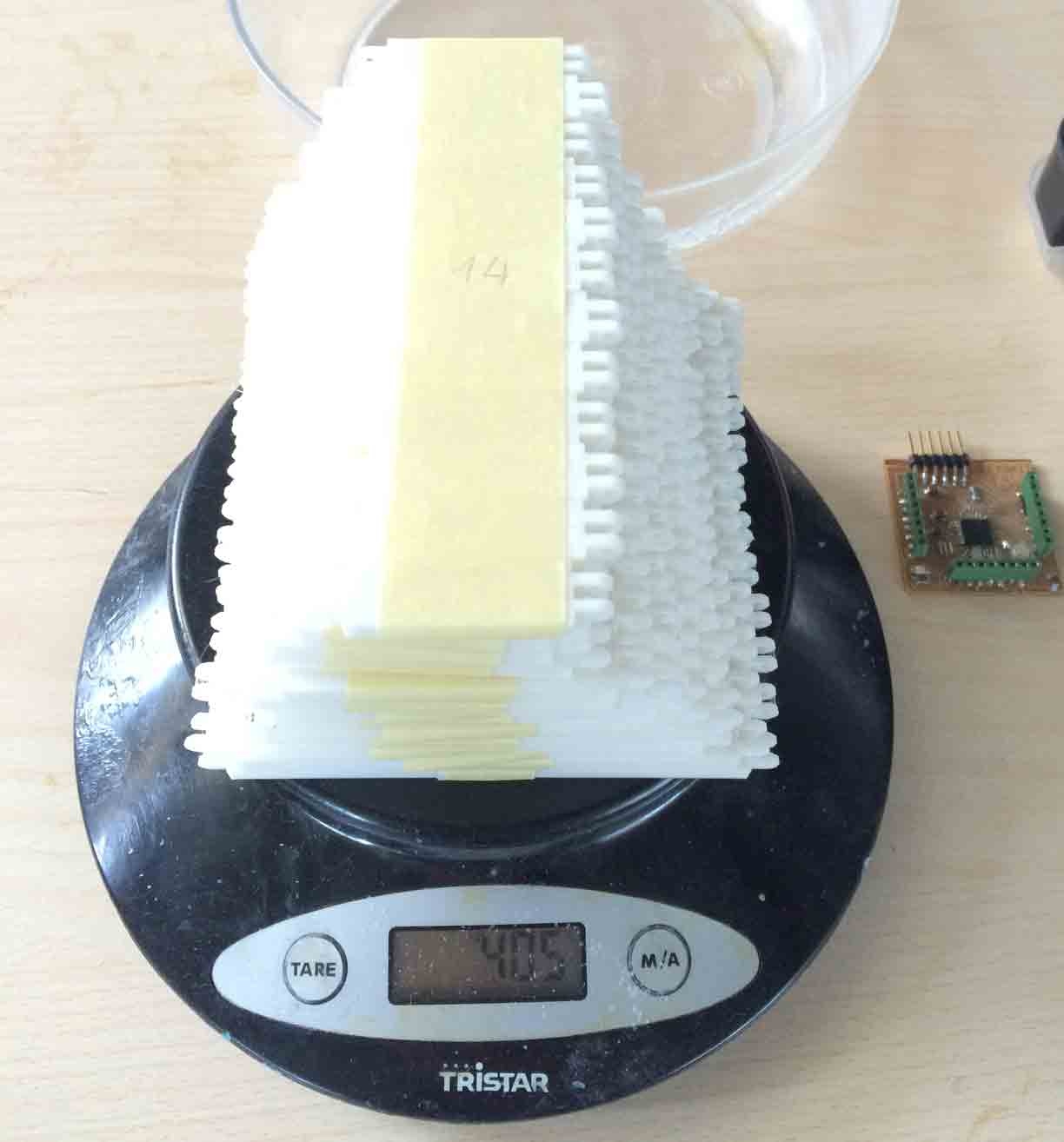
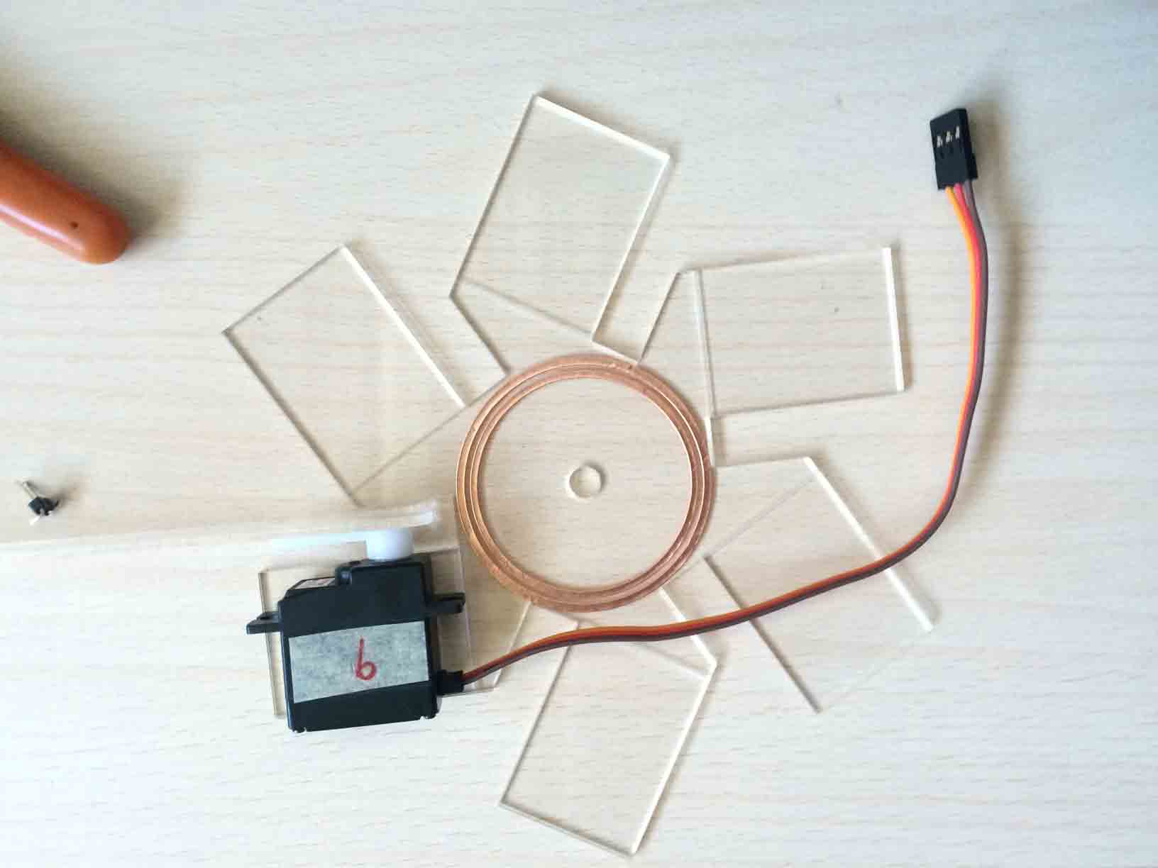
Weighing a sector of the dome. |
Deployment of the dome pieces and its servos. |
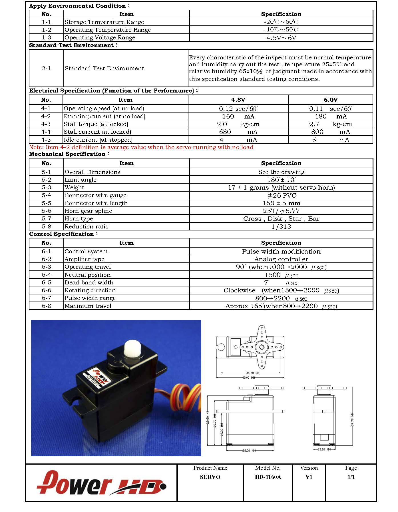
The kind of servos I chose (HD-1160A) transmit 2.7 Kg/cm of power to each blade of the structure.
|
HD-1160A servo data sheet. |
Programming the servo code
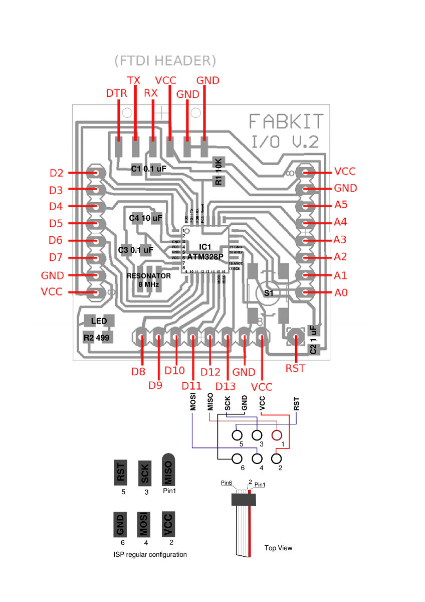
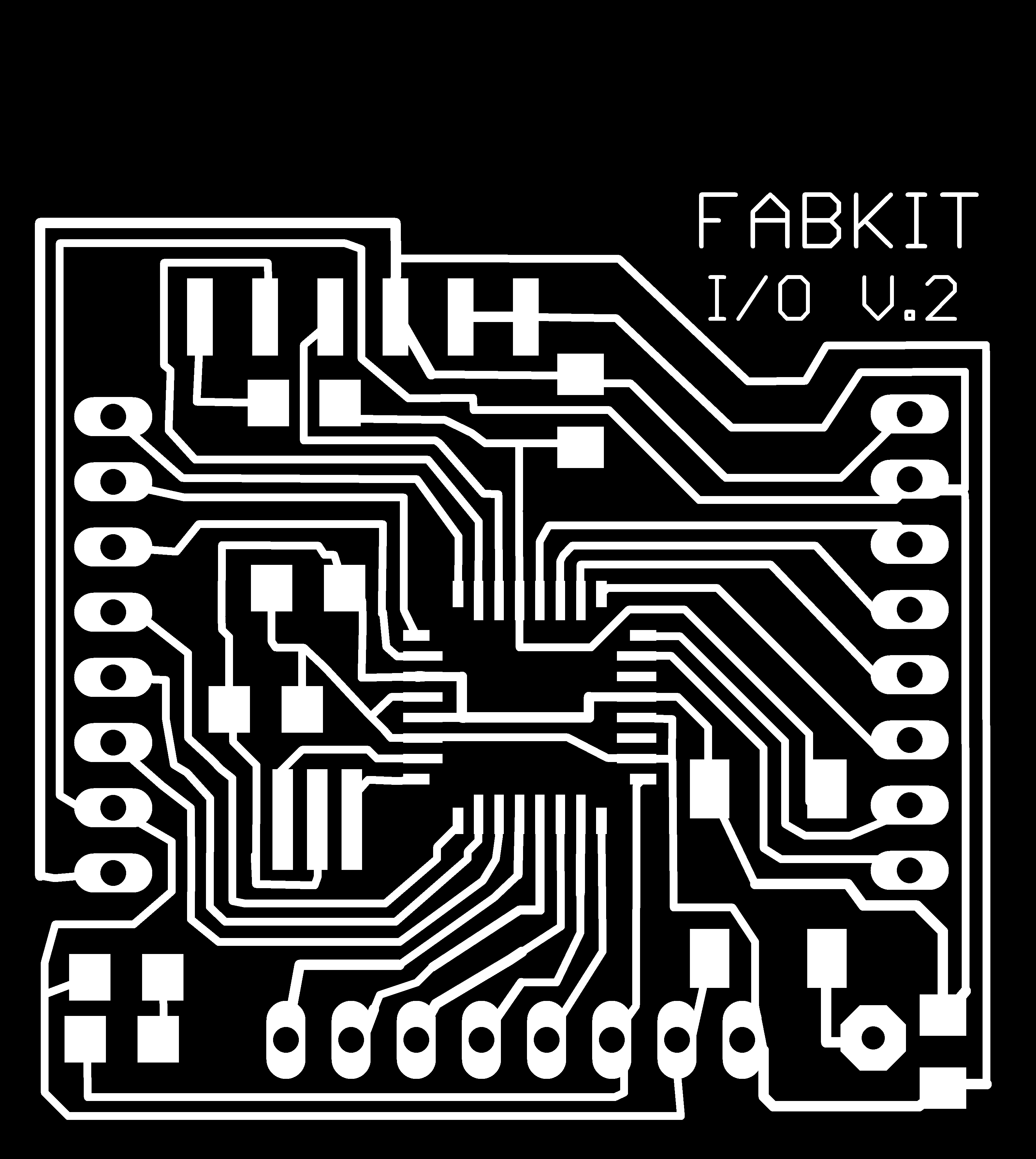
I want to move up and down the dome with a phototransistor that transforms the input of the intensity of the light in an output signal trough six servo motors, so I need to fabricate my own Fabduino board in order to control the signals.
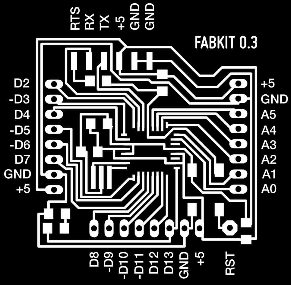
First of all in order to better undertand the FabKit board I made a modification introducing the initials of each pin to know where I can attach the PMW signal of the servos so I marked it with a dash close to the initials (D3,D5,D6,D9,D10,D11).
|
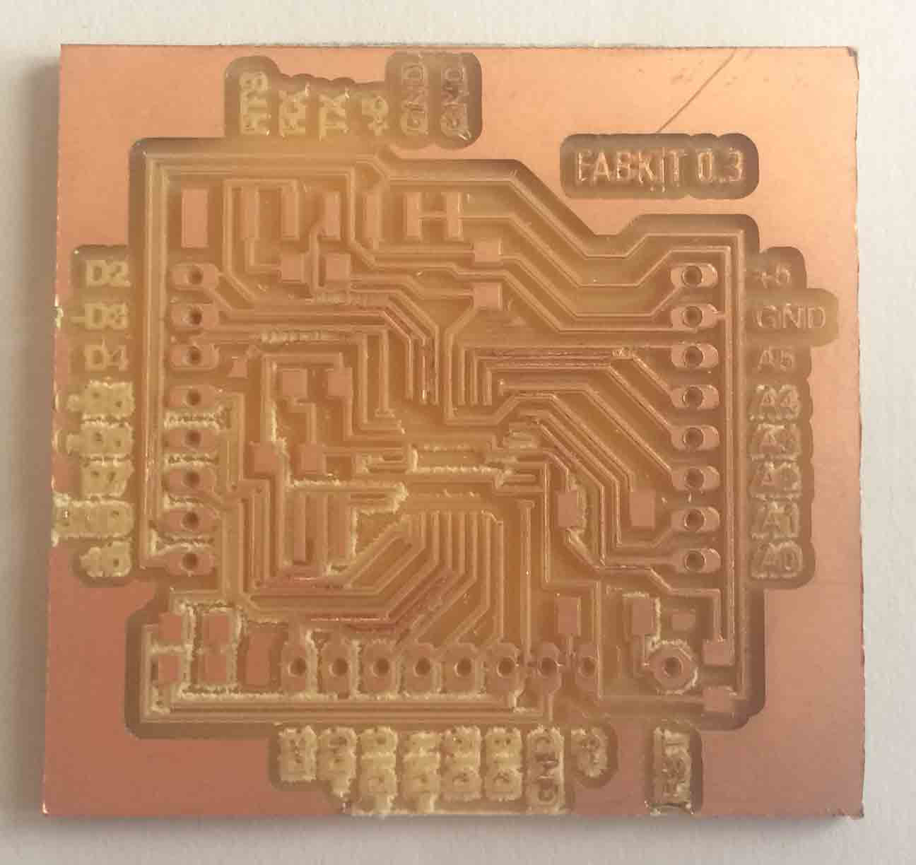 |
Modification introducing the initials in the FabKit 0.3. |
Failure while milling with a 0.1 mm diameter tool. |
But the FabKit 0.3 I chose needs to be milled with the smallest tool I know and I broke it milling with the Modela. So then I had to simply reproduce a FabKit i/o v2 board that could be milled by a 0.4 mm diameter tool.
|
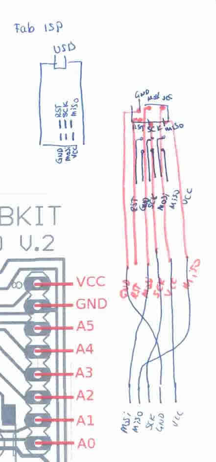 |
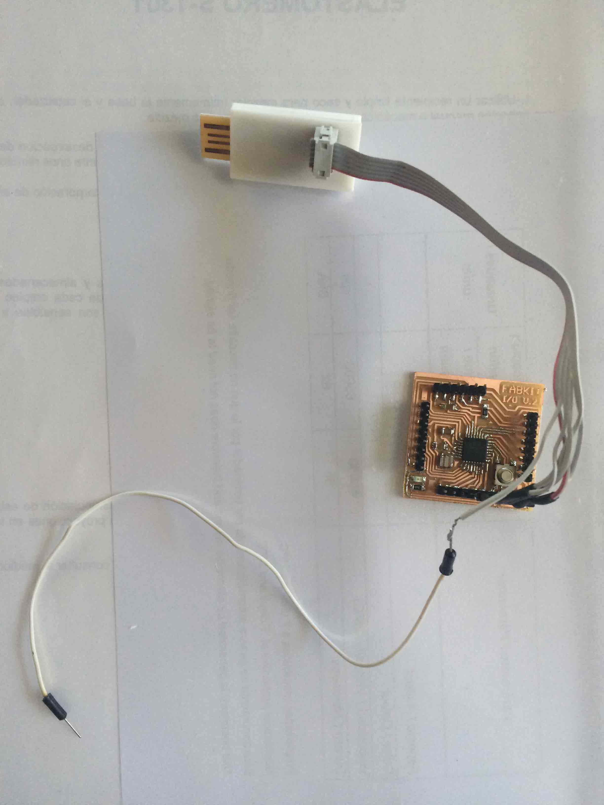
Programing Fabduino Fabkit v2 with an special cable throgh my FabISP. |
|
But first of all this Fabduino board works with an Atmega 328 and Arduino IDE is supposed to support Atmega 328p so I had to follow a tutorial where it was explained how to change the code in the boards.txt file to let Arduino IDE work with our Fabduino. To find this file you should go trough Equipo/C/Archivos de programa (x86)/Arduino/hardware/ and edit board.txt file with Notepad++ or similar to change the signature (line 9038) from 0x0F to 0x14.
|
 |
Changing the signature of the Atmega 328 in boards.txt |
After programming my FabKit through my FabISP. |
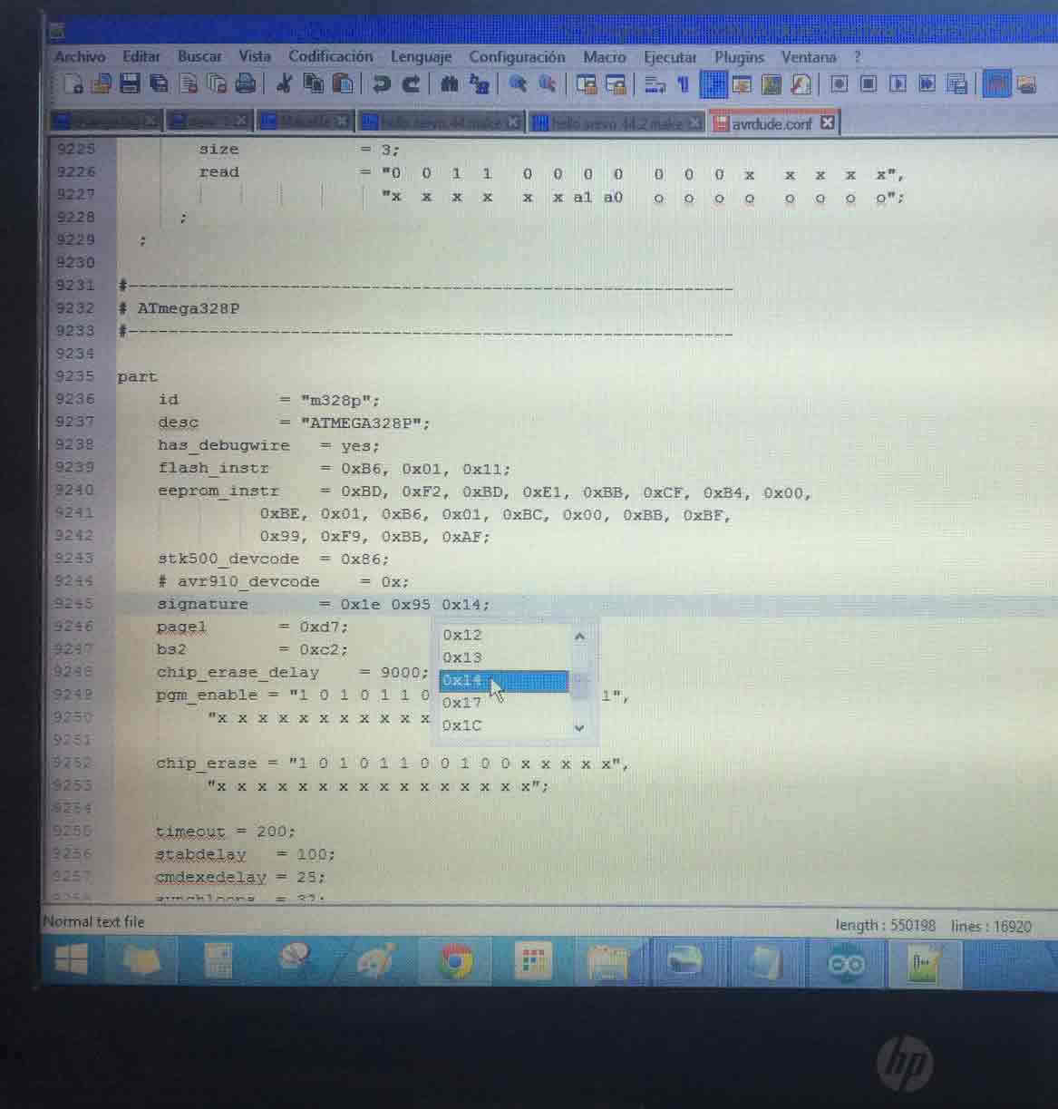
Then save the conf file and go to burn bootloader using the appropriate 328p board. Once bootloader has been burnt, go back to the conf file and undo the changes back to read 0x0F. You can now program your board through Arduino IDE.
|
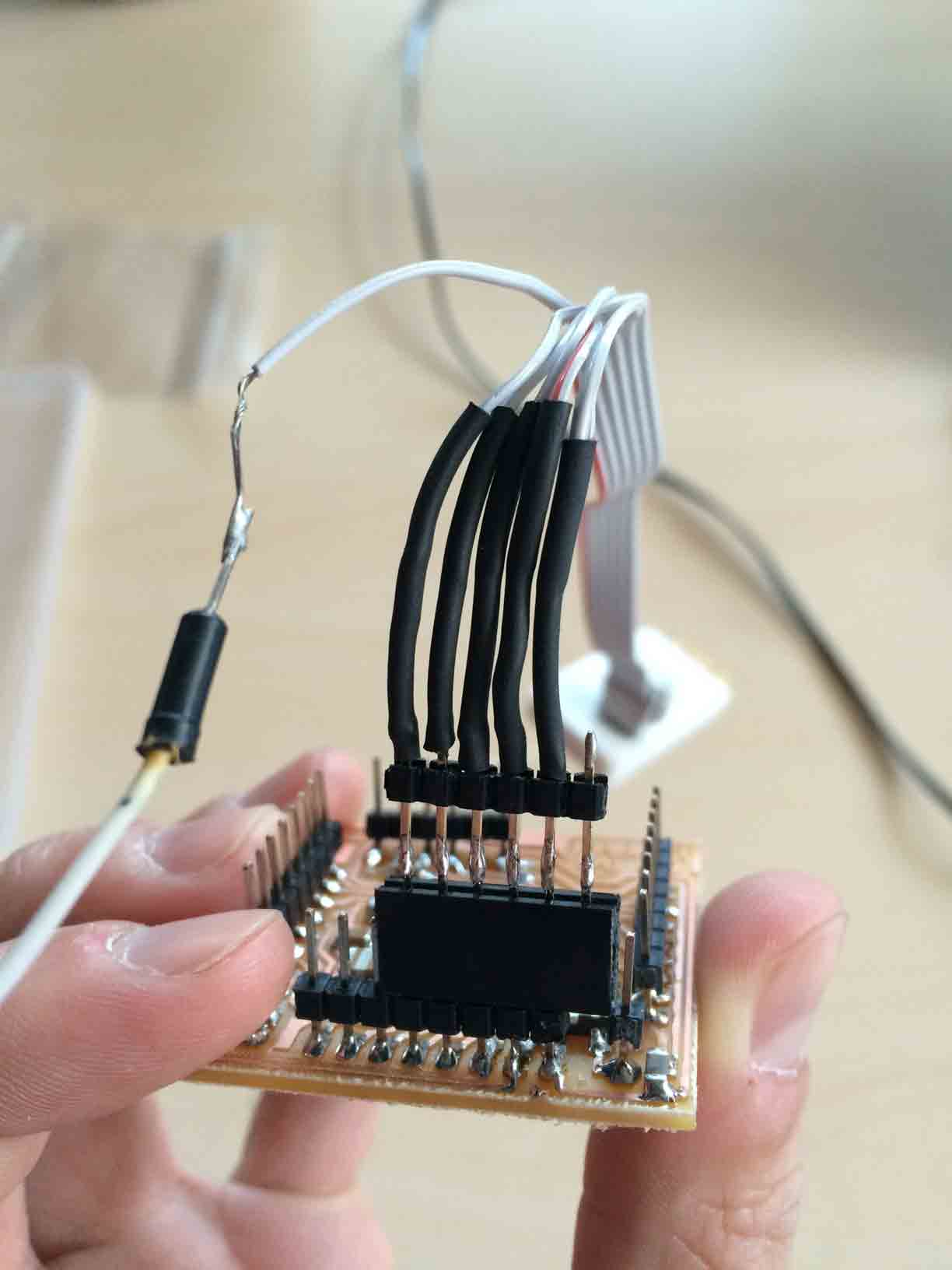 |
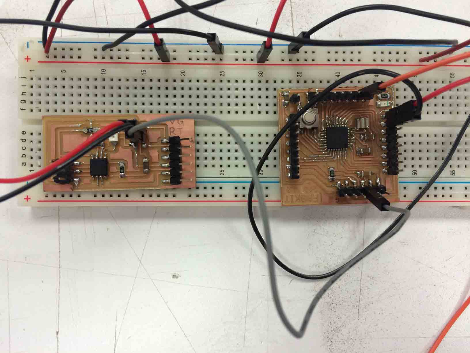
Connections between Fabduino Fabkit v2 and FabISP. |
|
To program the Atmega 328 board with my FabISP trhough Arduino you should go to Tools and select USBtinyISP as programmer and choose Arduino Pro (5V, 16MHz) Atmega 328 as your card and then go to Tools and play Burn bootloader.
Debugging the electronic circuit design: programming and connections
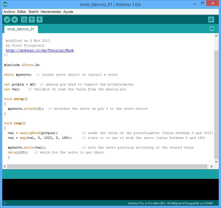
I used the Arduino IDE to program my FabKit starting from an exemple code for servo called Knob by Michal Rinott that controls a servo position using a potentiometer (variable resistor).
So the modifications I have made in this code were change the number of attached pins for the servos and the range of values of the degrees of rotation I want the servos to move:
/*
Controlling a servo position using a potentiometer (variable resistor)
by Michal Rinott <http://people.interaction-ivrea.it/m.rinott>
modified on 8 Nov 2013
by Scott Fitzgerald
http://arduino.cc/en/Tutorial/Knob
*/
#include <Servo.h>
Servo myservo3; // create servo object to control a servo
Servo myservo5;
Servo myservo6;
Servo myservo9;
Servo myservo10;
Servo myservo11;
int potpin = A0; // analog pin used to connect the potentiometer
int val; // variable to read the value from the analog pin
void setup()
{
myservo3.attach(3); // attaches the servo on pin 3 to the servo object
myservo5.attach(5);
myservo6.attach(6);
myservo9.attach(9);
myservo10.attach(10);
myservo11.attach(11);
}
void loop()
{
val = analogRead(potpin); // reads the value of the potentiometer (value between 0 and 1023)
val = map(val, 1, 1023, 60, 10); // scale it to use it with the servo (value between 0 and 180)
myservo3.write(val); // sets the servo position according to the scaled value
myservo5.write(val);
myservo6.write(val);
myservo9.write(val);
myservo10.write(val);
myservo11.write(val);
delay(15); // waits for the servo to get there
}
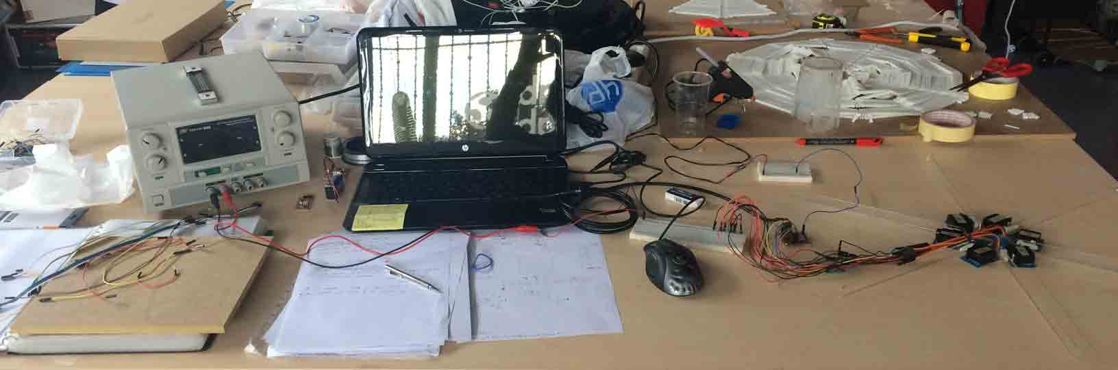
At the same time I started a debugging process that allows me to better understand the progress and reduce or increasing system complexity as I need:
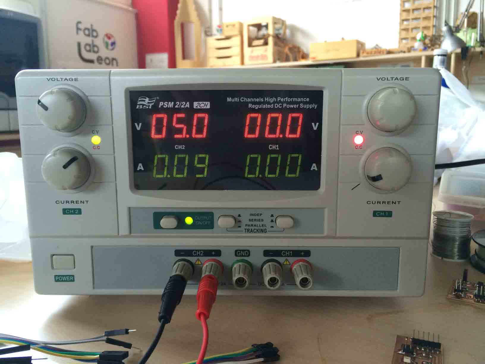
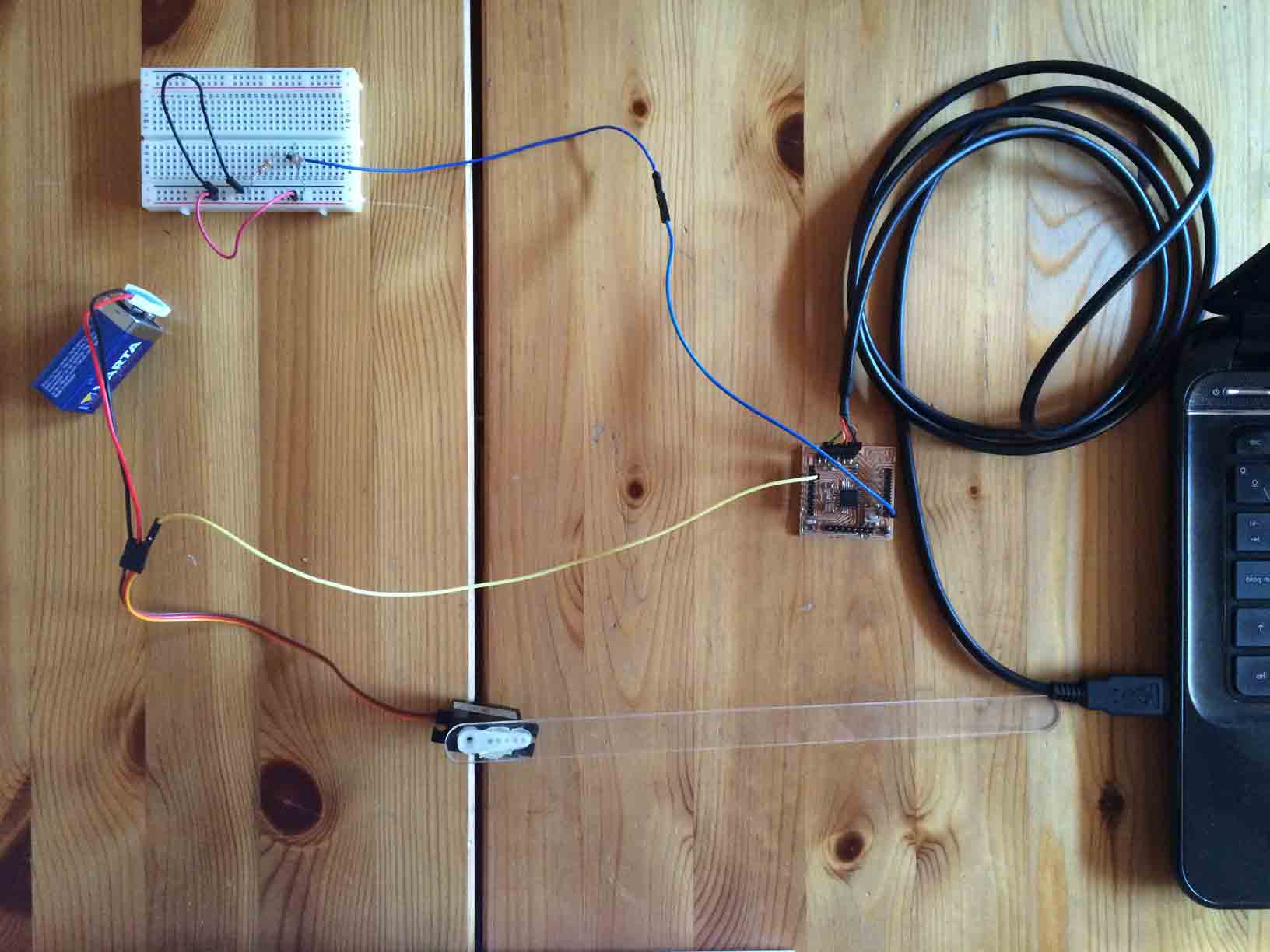
1 I started connecting 6 servos electricaly support by a power supply to the Fabkit >> that makes the servos crazy and I was not able to control the power.
|
 |
Power supply. |
Servo circuit powered by a power supply, Fabkit powered by FTDI and sensor powered by a mobile power transformer |
2 I disconnected everithing and start one by one powering one servo with a battery >> the servo turns until the end and emits a scream noise.
|
 |
Battery electric supply for the servo. |
FTDI cable electric supply for the servo. |
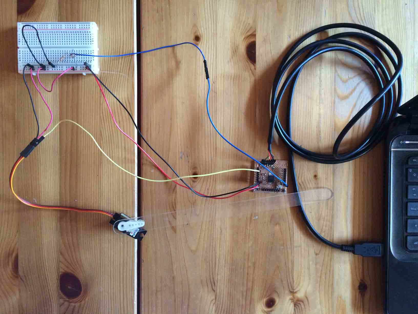
3 I connected only 1 servo and every VCC and GND to the FabKit powering everithing by the FTDI cable >> the servo moves cleaner and did not sound.
Déployé Dome (1 servo) by Fabricio Santos from Fabricio Santos on Vimeo.
4 I connected 2 servos powered by the FTDI cable >> the servos move at the same time and did not sound.
Déployé Dome (2 servo) by Fabricio Santos from Fabricio Santos on Vimeo.
5 I connected 6 servos powered by the FTDI cable >> the servos move at the same time but with some spasms.
Déployé Dome (6 servo) by Fabricio Santos from Fabricio Santos on Vimeo.
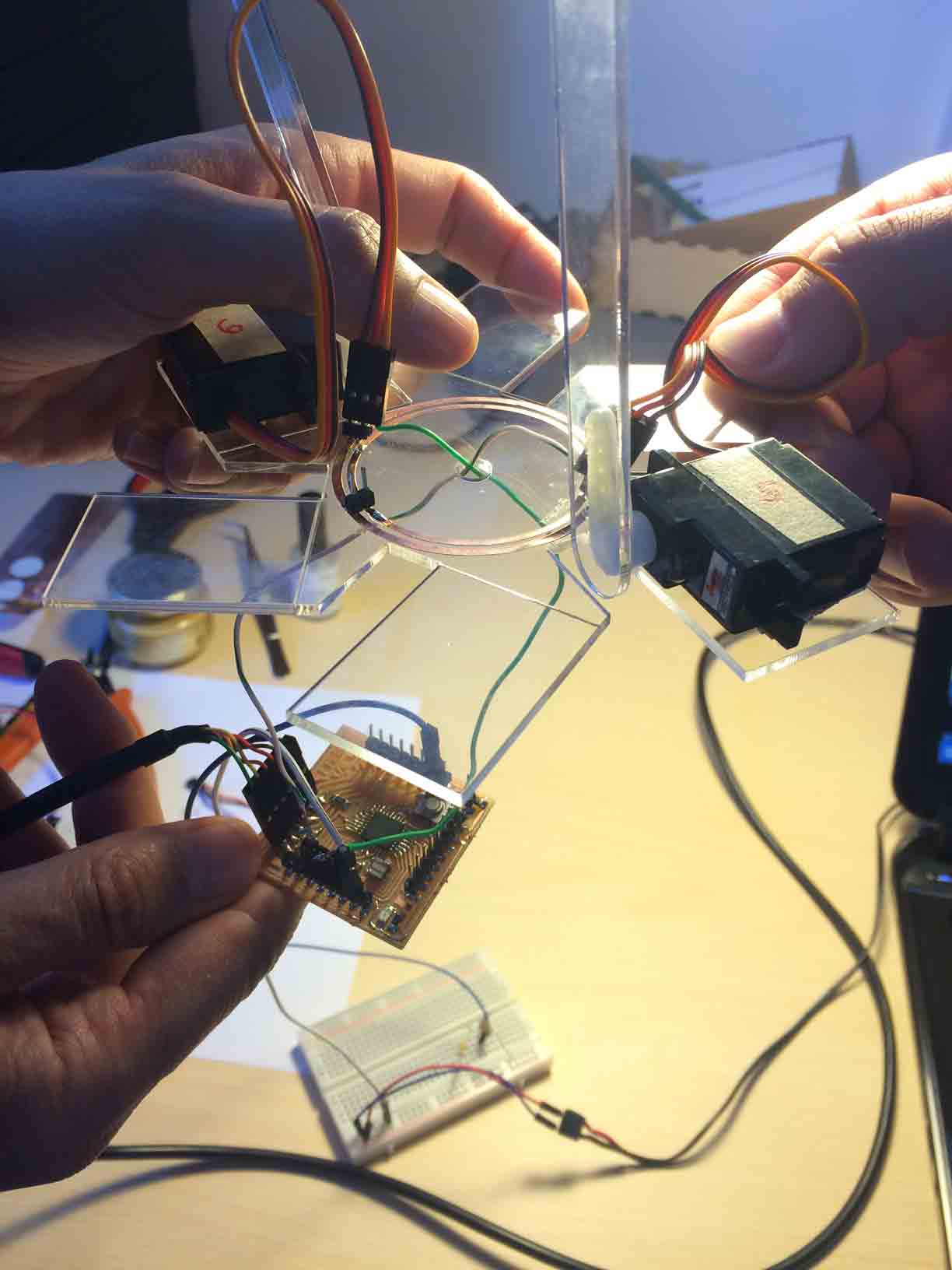
6 I connected 6 servos powered by the FTDI cable mounted on the structure >> the servos move at the same time but with some spasms.
Déployé Dome (6 servo structure) by Fabricio Santos from Fabricio Santos on Vimeo.
In conclusion when I attached only 1 or 2 servos to the Fabkit the result is a clean motion, but when there are 6 it makes noise in their motion.
Déployé Dome by Fabricio Santos from Fabricio Santos on Vimeo.
Things I need to continue testing:
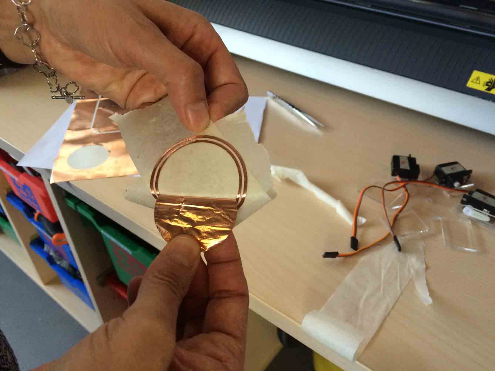
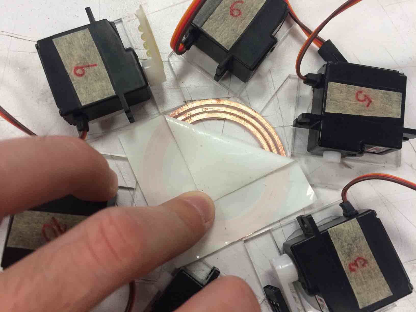
- Join each VCC, GND and PMW of every servos to one of each, it is to attach only 3 cables in the Fabkit hoping for the spasms of the servos to stop and have a clean motion. And I want to do it by joining the cables in a triple concentrical circuit made of adhesive cupper made in the vinyl cutter machine. Besides solving the problem, aesthetically it will look better because I would remove 15 cables.
|
 |
 |
Cutting the cupper with the vinyl cutter. |
Transferring the cupper to the structure´s crown. |
Connecting soldering pins. |
|
 |
 |
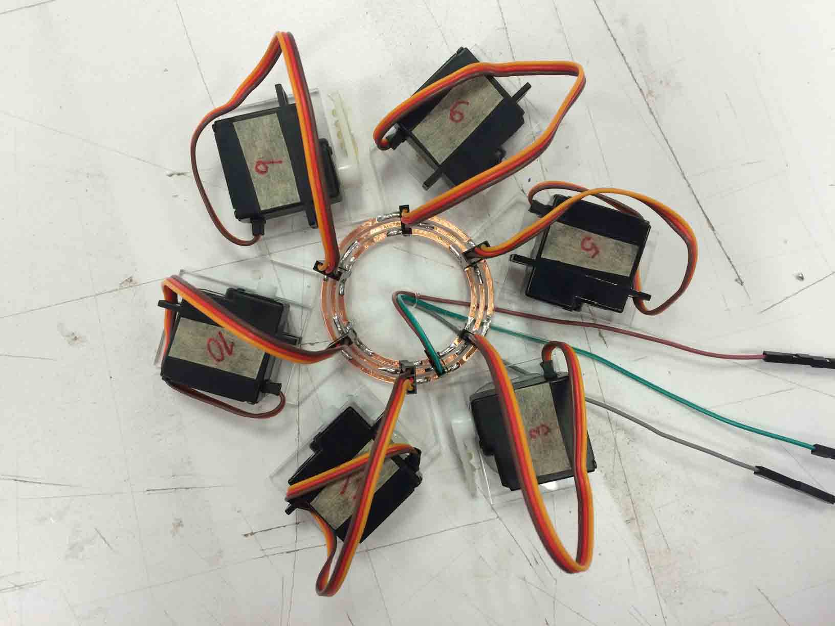 |
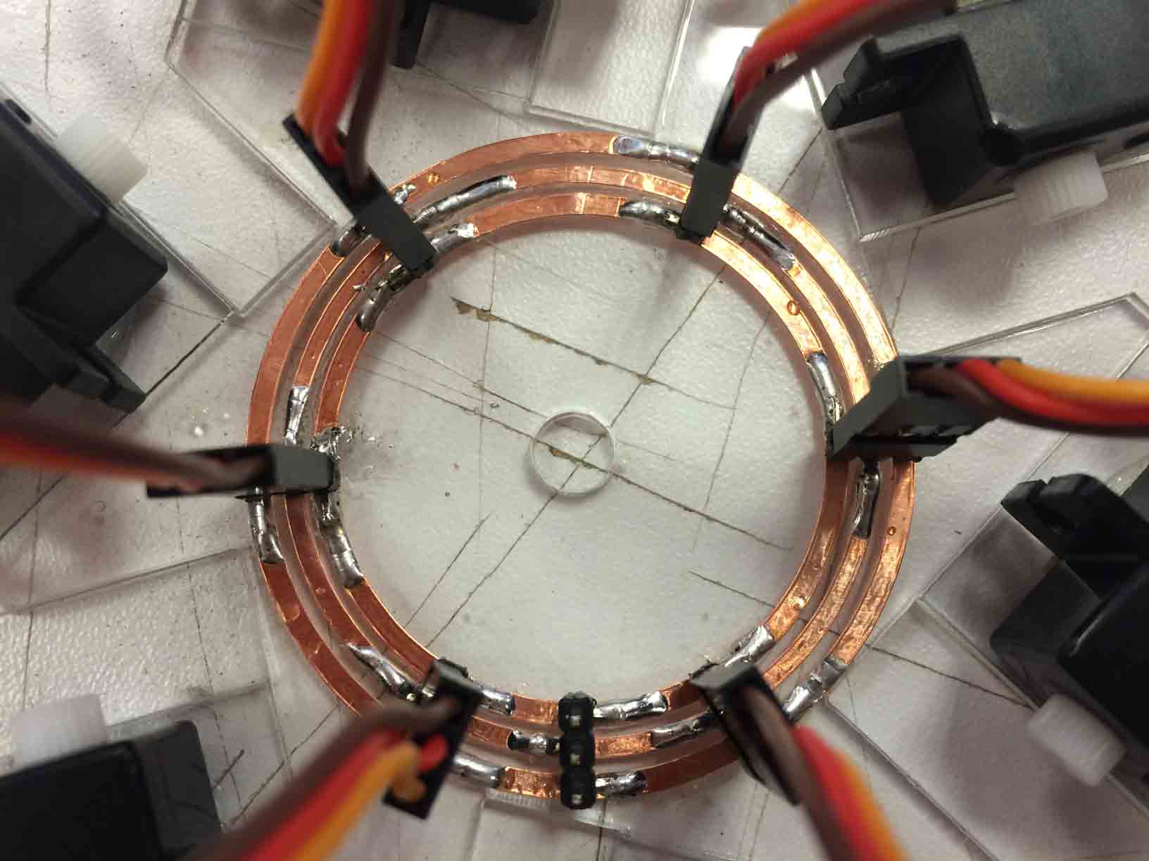
Replacing servo connections. |
Transferring the cupper. |
Connecting soldering pins. |
Only three cables to the board. |
- Replace the sensor installed on the breadboard for me Hello Light board designed in the input assignment:
|
 |
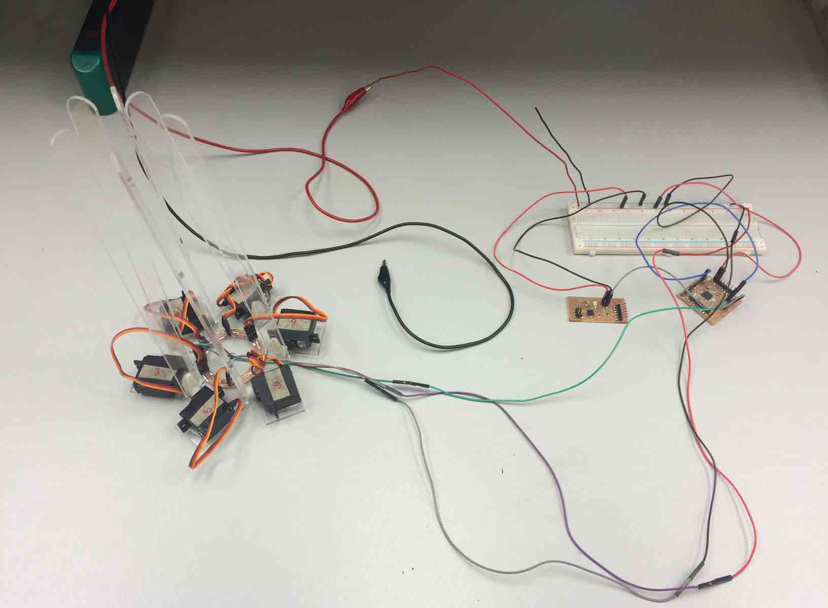
Entire electric circuit being tested. |
FabKit reading information from the Hello Light to the servos. |
- Improve the code taking the example of programs used in other assignments (like python in the Interface one) I modified some lines according to my circuit needs:
#include <Servo.h>
int sensorValue = 0; // variable to store the value coming from the sensor
int centinela = 0;
char byte1, byte2, byte3, byte4, bajo, alto;
int value, posServo;
Servo myservo;
void setup() {
pinMode(12, OUTPUT);
pinMode(13, OUTPUT);
Serial.begin(9600);
myservo.attach(9);
}
void loop() {
if(Serial.available() > 0){
byte1 = byte2;
byte2 = byte3;
byte3 = byte4;
byte4 = Serial.read(); //Leer La secuencia de inicio
if ((byte1 == 1) & (byte2 == 2) & (byte3 == 3) & (byte4 == 4)){
if(centinela == 1 ){
digitalWrite(13, HIGH);
centinela = 0;
}
else{
digitalWrite(13, LOW);
centinela = 1;
}
while(Serial.available()==0);
bajo = Serial.read();
while(Serial.available()==0);
alto = Serial.read();
value = 256*alto + bajo;
posServo = map(value, 0, 1024, 0, 180);
myservo.write(posServo);
}
}
}
|
Déployé Dome lifted >> low light intensity |
|
Déployé Dome flattened >> high light intensity |
In conclusion it does not work as I were imagine, but for my it is a breakthrough that a prototype made by my hands were able to move. And I think the project is at a very interesting point of debugging, so I will continue with it!
- - -
Files:
· Déployé 3D printed pieces (Rhinoceros)
· Laser cutting structure (Rhinoceros)
· Servo programming code (Arduino)
|
Déployé Dome by Fabricio Santos is licensed under a Creative Commons Reconocimiento-NoComercial-CompartirIgual 4.0 Internacional License. |

