Exercise 14
06.05.2015
Interface and Application Programming
Assignment
Scarabocchio
During this week I had to make a project for CASA JASMINA and in particular a toy for the children room.I like machine that draw and inspired from my past I decided to make a digital spyrograph and I call it SCARABOCCHIO
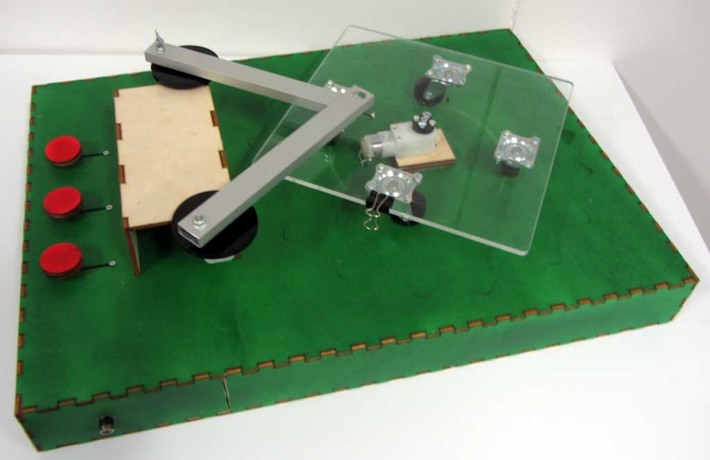
It consist in 3 DC motors and 3 linear potentiometer, every potentiometer control one motor and changing the speed of every motor is possible to make different draw.
For this project I haven't time to make a custom board so I decided to make one on a proto shield, the circuit is really easy to made following this schematic
In the protoshield I've just triplicate this scheme and put the motor on pin 3 - 6 -11
For the event is better to use this toy with a mechanical feedback so I leaved it with potentiometer to control the speed, but I tried also to make some digital!
Searching on internet I see that is very easy to control input and output from Processing
There are two library that are perfect for the scope:
Arduino Processing Library
ControlP5
these library with Firmata work very well
In Processing I followed a tutorial to write this simple sketch
controlP5.addSliderdraw a slider
arduino.analogWrite(3, Motor1);write signal in the selected pin
	import processing.serial.*;
import cc.arduino.*;
import controlP5.*;
ControlP5 controlP5;
Arduino arduino;
Textarea myTextarea;

int Motor1 = 5; // 0-255

int Motor2 = 5; // 0-255

int Motor3 = 5; // 0-255

void setup() {

 size(400,400);

 println(Arduino.list());
 arduino = new Arduino(this, Arduino.list()[0], 57600);

 for (int i = 0; i <= 13; i++)
 arduino.pinMode(i, Arduino.OUTPUT);

 controlP5 = new ControlP5(this);

 myTextarea = controlP5.addTextarea("txt1")
                  .setPosition(20,10)
                  .setSize(255,30)
                  .setFont(createFont("verdana",14))
                  .setLineHeight(14)
                  .setColor(color(0))
                  .setColorBackground(color(204))
                  .setColorForeground(color(204));
                  ;
  myTextarea.setText("Scarabocchio controller"
                   );

 controlP5.addSlider("Motor1",0,255,Motor1,40,60,255,40);

 controlP5.addSlider("Motor2",0,255,Motor2,40,160,255,40);

 controlP5.addSlider("Motor3",0,255,Motor3,40,260,255,40);

}
void draw() {
 arduino.analogWrite(3, Motor1);

 arduino.analogWrite(6, Motor2);

 arduino.analogWrite(11, Motor3);

}
This is the PC side controller 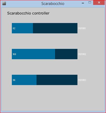
The arduino side is more simple, I had just to upload the SimpleAnalogFirmata sketch
/*
 * Firmata is a generic protocol for communicating with microcontrollers
 * from software on a host computer. It is intended to work with
 * any host computer software package.
 *
 * To download a host software package, please clink on the following link
 * to open the download page in your default browser.
 *
 * http://firmata.org/wiki/Download
 */

/* Supports as many analog inputs and analog PWM outputs as possible.
 *
 * This example code is in the public domain.
 */
#include <Firmata.h>

byte analogPin = 0;

void analogWriteCallback(byte pin, int value)
{
  if (IS_PIN_PWM(pin)) {
    pinMode(PIN_TO_DIGITAL(pin), OUTPUT);
    analogWrite(PIN_TO_PWM(pin), value);
  }
}

void setup()
{
  Firmata.setFirmwareVersion(0, 1);
  Firmata.attach(ANALOG_MESSAGE, analogWriteCallback);
  Firmata.begin(57600);
}

void loop()
{
  while (Firmata.available()) {
    Firmata.processInput();
  }
  // do one analogRead per loop, so if PC is sending a lot of
  // analog write messages, we will only delay 1 analogRead
  Firmata.sendAnalog(analogPin, analogRead(analogPin));
  analogPin = analogPin + 1;
  if (analogPin >= TOTAL_ANALOG_PINS) analogPin = 0;
}
Below a sample video of Scarabocchio controlled by
Processing