Week #11 || Input Devices
Software used:
Machine used:
Setbacks:
1. Running too fast
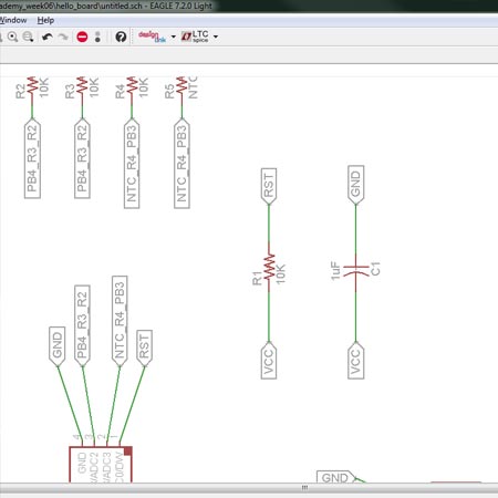
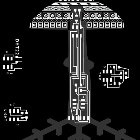
Last week I had a very cool idea. I want the PCB for my final project to have the shape of my mushroom logo. So this week we had to make input sensor devices, and I decided to take Neil's designs, pile them together, move things around, and make it fit in my mushroom. I also wanted to make the atTiny45 board seperate from the sensors, so you can connect and disconnect different sensors to a single board. So on I went!
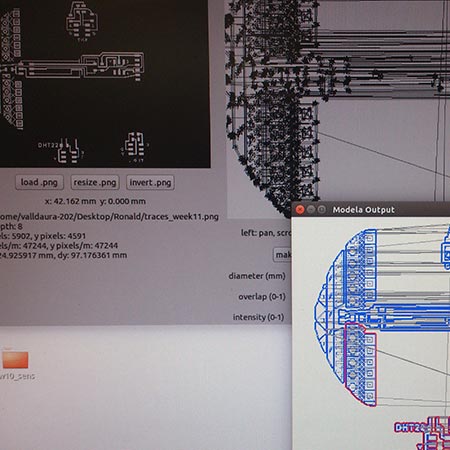
The process in Eagle went very smooth, I feel comfortable in the program, and designing the board went quite smooth. One thing I did not do well, was to choose ISP header for the connecter to the remote sensors, in lack of a better way to connect them. I forgot to mirror the inputs and outputs on the sending and receiving headers, so I could not align the sensors with the atTiny45 board with the cable. After one and a half day of designing and making, I had to conclude this setup was not made to work once I started attempting to use it. But as you can see in the pictures, it looks awesome!!
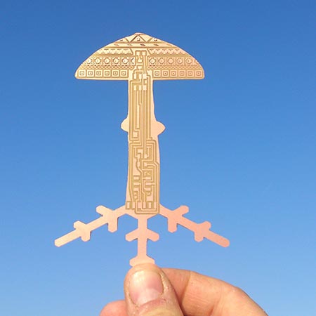
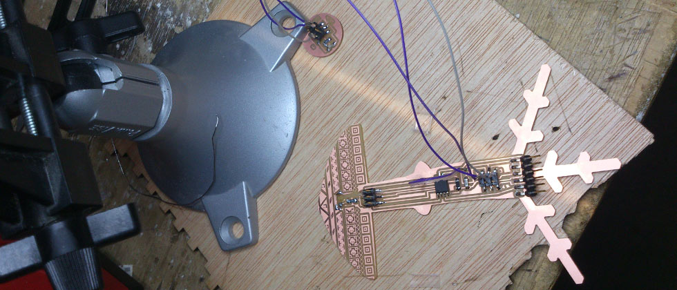
So, even though I did not get this to work yet, this has greatly inspired me in terms of electronics design. I will keep developping this!
2. Hello Light
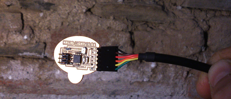
As time was getting tight after the first failure, I decided to just make one of the boards as it is. I chose the light sensor with the darlington phototransistor. I copied Neil's design to make sure I wouldn not make design/making errors. Once done, I followed AS220's tutorial to program it. I failed twice: The first I realized I had only soldered one foot of the atTiny45. The second time I failed to program it, I forgot to plug the USB into the computer. I was tired after a long couple of days. But then, it worked! The video below shows the light sensor in action!
Files
Click here to download the cutout and traces file PHOTOSHOP.