 Francesca Mereu
Project development
Goal
Goal of this final week is to document and build our final project, and track and document our progress
Project results
what tasks have been completed, and what tasks remain?
Completed:
- building the pressure sensor
- designing and stuffing the board
- programming the board
- developing the interface
- designing the shoe and the module case
- license
Remained:
- fabricate the shoe prototype by different materials
- connecting the bluetooth module and programming it
what has worked?
- pressure textile sensor
- custom board
- web interface with websocket
what hasn’t?
- web interface first version
- joint of the printed model
what questions need to be resolved?
- how using the insole to interact with another device?
- how dissemination of project results to relevant stakeholders?
- Which "exploitation" plan, as business model definition?
what will happen when?
I hope to wear this shoe on Fab11
what have you learned?
- manage a project in all parts of fabrication process;
- working all together
- solving the problem in many cases
- working with electronic components
- share results and ideas
Specifications
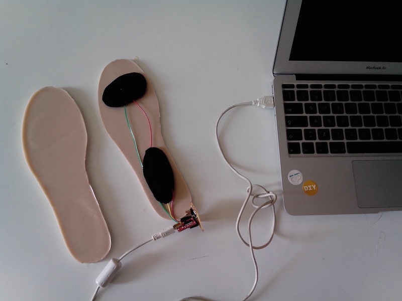
For the final project presentation I managed to build a basic version of “Esole” with the following specifications:
- silicon insole
- custom pressure textile sensor
- pressure board
- sole case(shoes) with module for the board
- serial connections
- web interface
- Basic Python API for controlling the above
The second version will have next addeds:
- bluetooth module hc 05
- battery holder
- flexible sole case
Architecture
The current prototype has the following architecture
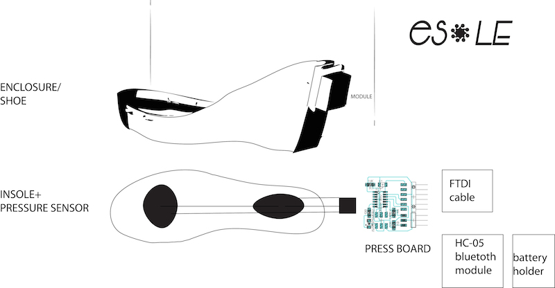
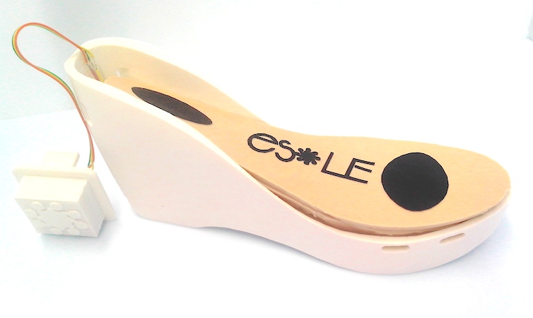
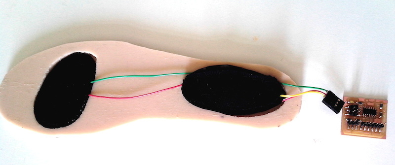
Parts, Case and the DIY sensor
The project is composed of a lot of parts: the insole with sensor, the board and the shoe-case with the module. The module is a case of the electronic components: as the board with the bluetooth module and the battery. When the sole is working the module is lighting.
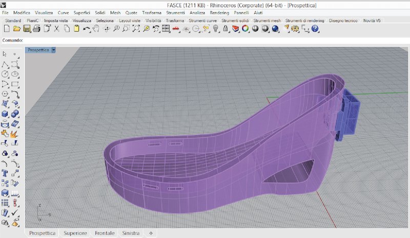
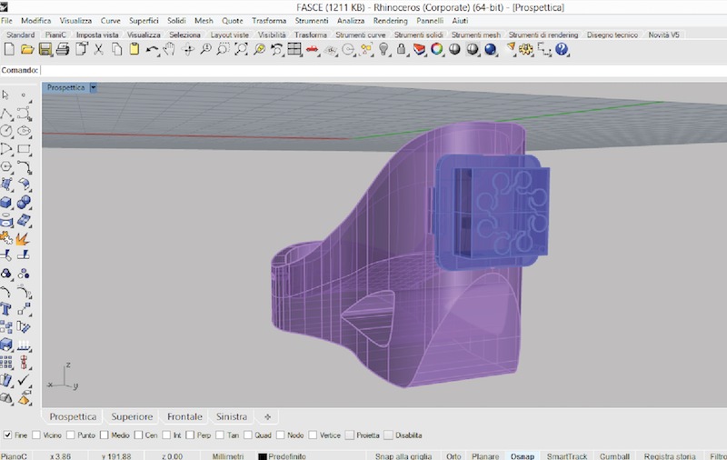
computer aided design: the shoe and the module
As I ‘m designer is important for me to make a good design for the shoe and the electronic module. I started from the concept of the heel but in a second step I studied the insole and from it I build my shoes. I was modelling this part by Rhinoceros and Sketchup, 3d computer graphics and computer aided design (CAD)applications software. Rhinoceros geometry is based on NURBS mathematical model, which focuses on producing mathematically precise rapresentation of curves and freeform surface in computer graphics. I prefered to use it for modelling the shoe, because I thinked to use Grasshopper, a Rhino plug-in, to project parametrically the shoe case.
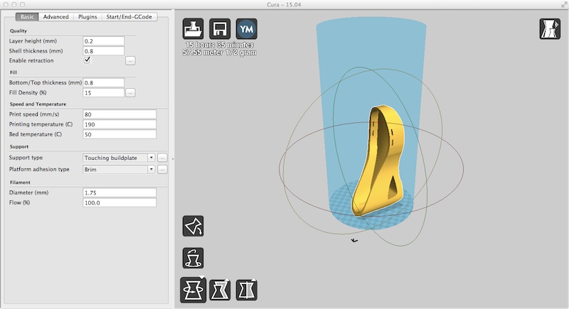
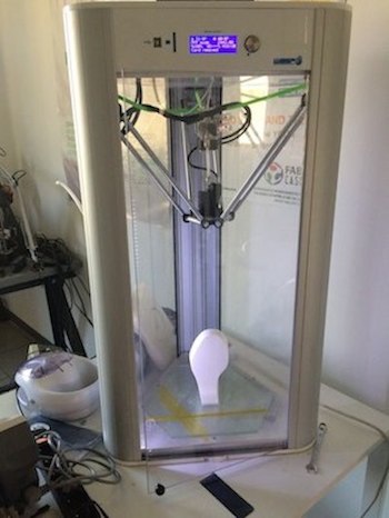
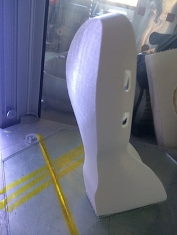
3d printing
The part of the packaging of the project is built with 3D printing and split in two parts: shoe and module,a little enclosure for the board and battery. Other parts don’t have any special requirements to be printed. Expect about 15 hours of printing to build the whole set at reasonable speed settings (i.e. 80mm/s). I used the WASP Delta 20x40. I made the insole in silicon rubber with a molding and casting technique, and the sensor with the velostat. The components to be printed are:
- enclosure-shoe
- case-module for electronics
Setting the printing
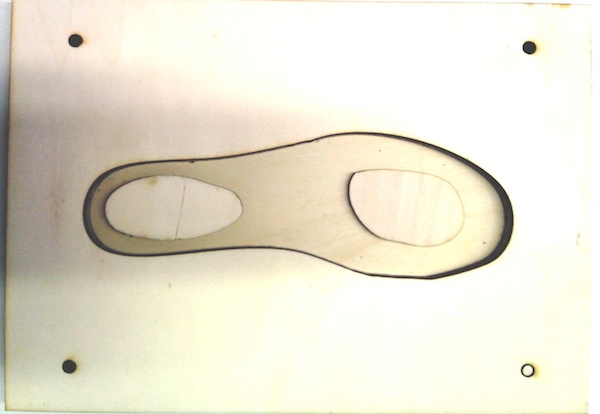
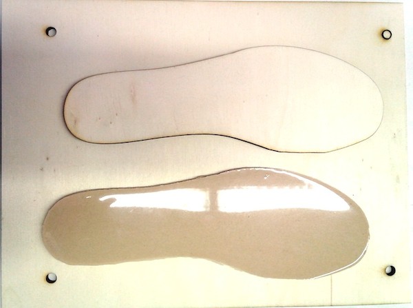
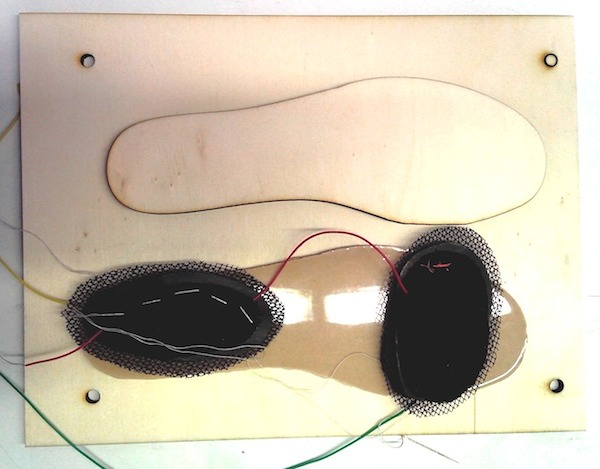
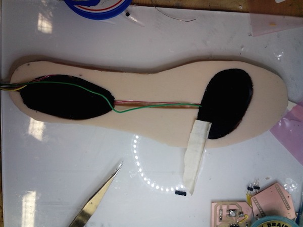
molding and casting: the insole
The first step of the making process is to prepare the base of the smart insole by the molding and casting tecnique. Then I prepared a mold cutting a wood panel (4x200x300 mm) by the lasercutter . I used 50mm thick birch plywood, and design must be adjusted for different materials. The cutting power I used on the FullSpectrum 90W laser cutter is 40% power 100% speed.
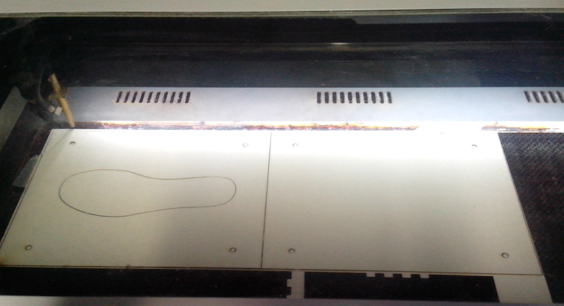
I used the silicone-rubber of “Smooth on”, in part of 150 g of part A and 5% of part B
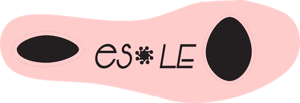
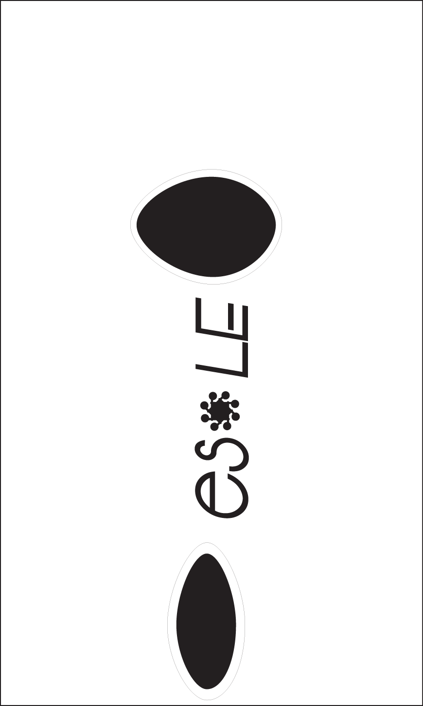
computer controlled cutting: sticker logo
To signalize the sole with the sensor I thinked to also prepared some stickers with logo, allowing to customize the products case and have a good design look.
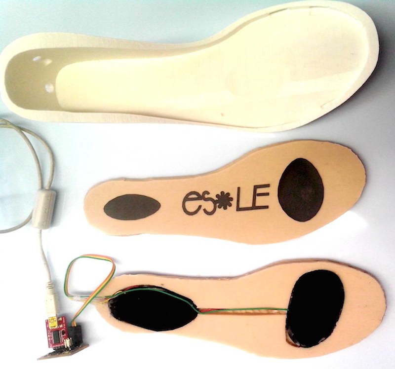
Input device: analog textile pressure sensor
I used Velostat/Linqstat (Carbon impregnated Polyethylene film ) and a conductive fabric to make an analog pressure sensor. Velostat is a piezoresistive material, meaning it’s electrical resistance decreases when pressure. It’s pressure-sensitive: squeezing it will reduce the resistance, so it’s handy for making flexible sensors. When sandwiched between two conductive layers, it has a wonderful range for making pressure and bend sensors. It can also be used for position sensing.
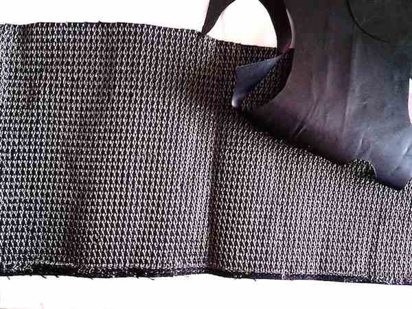
This analog press button works with resistive principle. It has a very high resistivity when not pressed, but its resistance goes down as soon as you press it. It works as a bend sensor as well. By connecting more sensors together it is possible to make a matrix analog switch.
The Analog textile pressbutton is a analog textile sensor that change his resistivity if you make pressure on it. It is useful for creating variable voltage divider that can be easily read by an Arduino.
Testing the sensor (part1)
So, first I tested the sensor with lilypad arduino, afterwards I tested it with my board. There’s the code that I used:
Int SensorPin = a5;    // Select the Input pin for the Sensor
Int LedPin = 13;      // Select the pin for the LED
Int SensorValue = 0;  // Variable to Store the Value Coming from the Sensor

Void Setup() {
  // Declare the LedPin as an OUTPUT:
  PinMode(LedPin, OUTPUT);
}

Void Loop() {
  // Read the Value from the Sensor:
  SensorValue = AnalogRead(SensorPin);
  // Turn the LedPin On
  DigitalWrite(LedPin, HIGH);
  // Stop the Program for <SensorValue> Milliseconds:
  Delay(SensorValue);
  // Turn the LedPin Off:
  DigitalWrite(LedPin, LOW);
  // Stop the Program for for <SensorValue> Milliseconds:
  Delay(SensorValue);
}
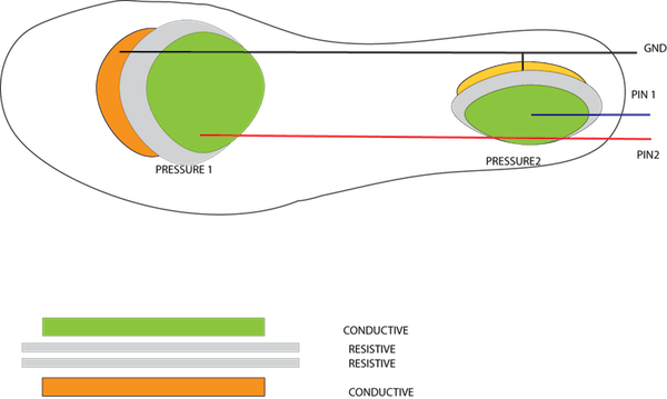
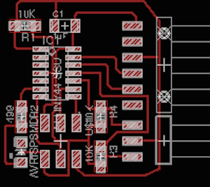
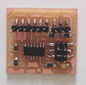
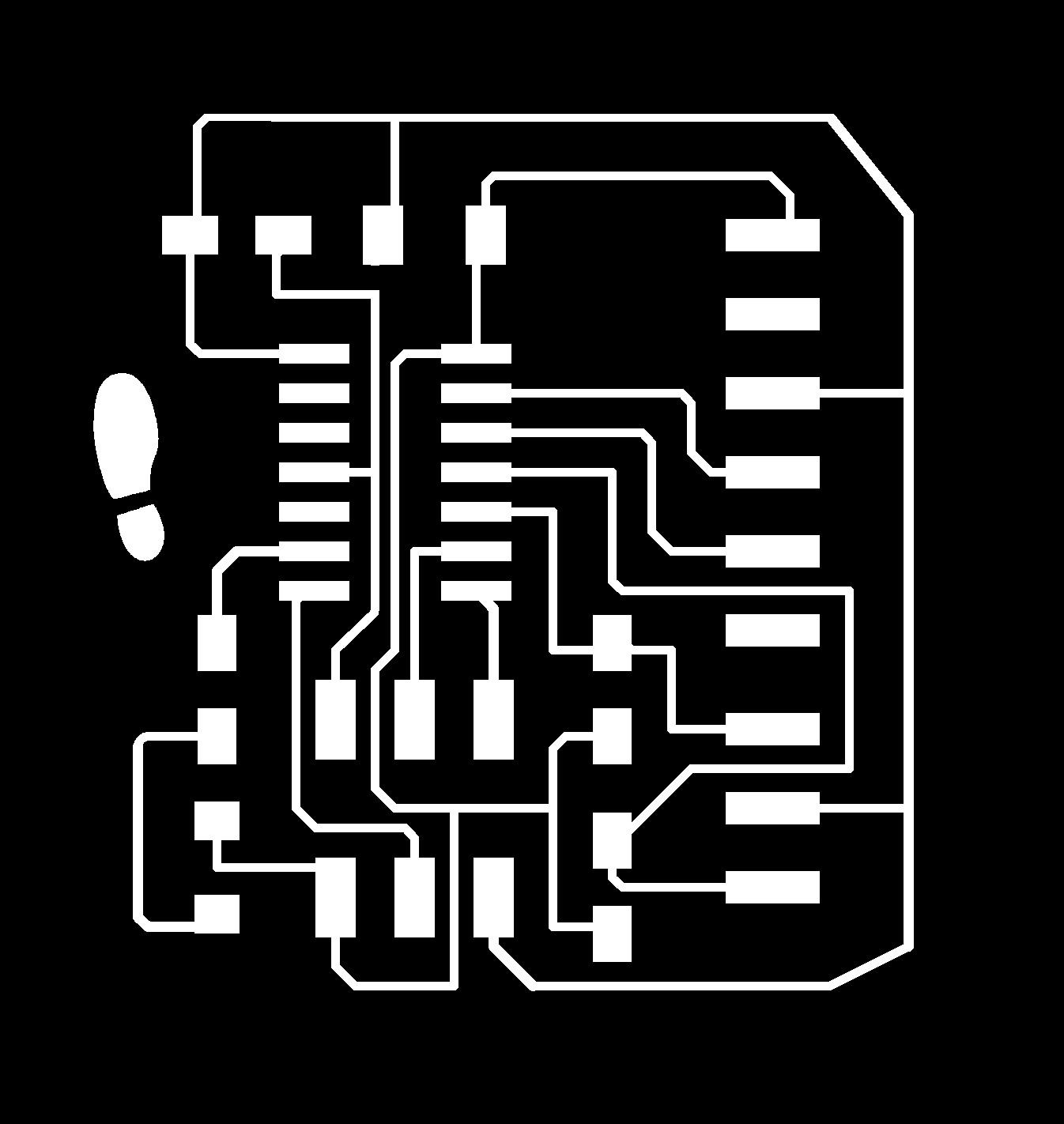
electronic design: “press-board”
This analog press button works with resistive principle. I designed the pressboard considerating three pins: two for the sensor (press1 and press2) and another for the VCC. These are the images of the schematic board from Eagle cad and the soldered board.
Testing the sensor (part2)
Finally I have programed the board in C. This is the code:
In the first part I defined the macro
 #include <avr/io.h>
 #include <util/delay.h>

 #define output(directions,pin) (directions |= pin) // set port direction for output
 #define set(port,pin) (port |= pin) // set port pin
 #define clear(port,pin) (port &= (~pin)) // clear port pin
 #define pin_test(pins,pin) (pins & pin) // test for port pin
 #define bit_test(byte,bit) (byte & (1 << bit)) // test for bit set
 #define bit_delay_time 100 // bit delay for 9600 with overhead
 #define bit_delay() _delay_us(bit_delay_time) // RS232 bit delay
 #define half_bit_delay() _delay_us(bit_delay_time/2) // RS232 half bit delay
 #define char_delay() _delay_ms(10) // char delay

 #define serial_port PORTA
 #define serial_direction DDRA
 #define serial_pin_out (1 << PA1) // pin Tx serial
 // write a char into a serial port
In this part it send character in txchar on port pin
void put_char(volatile unsigned char *port, unsigned char pin, char txchar) {
<	//
	// send character in txchar on port pin
	//	 assumes line driver (inverts bits)
	//
	// start bit
	//
	clear(*port,pin);
	bit_delay();
	//
	// unrolled loop to write data bits
	//
	if bit_test(txchar,0)
		set(*port,pin);
	else
		clear(*port,pin);
	bit_delay();
	if bit_test(txchar,1)
		set(*port,pin);
	else
		clear(*port,pin);
	bit_delay();
	if bit_test(txchar,2)
		set(*port,pin);
	else
		clear(*port,pin);
	bit_delay();
	if bit_test(txchar,3)
		set(*port,pin);
	else
		clear(*port,pin);
	bit_delay();
	if bit_test(txchar,4)
		set(*port,pin);
	else
		clear(*port,pin);
	bit_delay();
	if bit_test(txchar,5)
		set(*port,pin);
	else
		clear(*port,pin);
	bit_delay();
	if bit_test(txchar,6)
		set(*port,pin);
	else
		clear(*port,pin);
	bit_delay();
	if bit_test(txchar,7)
		set(*port,pin);
	else
		clear(*port,pin);
	bit_delay();
	//
	// stop bit
	//
	set(*port,pin);
	bit_delay();
	//
	// char delay
	//
	bit_delay();
}>
In this part we read the sensor value on pin 1
// read sensor value
	void readsensor1(){
	   	static char chr;
		   //initialize ADC
		   // init A/D
		   //
		   ADMUX =  (0 << REFS1) | (0 << REFS0) // Vcc ref
		      | (0 << ADLAR) // right adjust
		      | (0 << MUX5) | (0 << MUX4) | (0 << MUX3) | (0 << MUX2) | (1 << MUX1) | (1 << MUX0); // ADC3 -configure pin
		   ADCSRA = (1 << ADEN) // enable
		      | (1 << ADPS2) | (1 << ADPS1) | (1 << ADPS0); // prescaler /128
		   //
	       //
	       // initiate conversion
	       //
	       ADCSRA |= (1 << ADSC);
	       //
	       // wait for completion
	       //
	       while (ADCSRA & (1 << ADSC)){ // while adsc not 0
			   // nothing

   }
   //
   // send result
   //
   chr = ADCL;
   put_char(&serial_port, serial_pin_out, chr);
   char_delay();
   chr = ADCH;
   put_char(&serial_port, serial_pin_out, chr);
   char_delay();
   }
In this part we read the sensor value on pin2
void readsensor2(){
   	static char chr;
	   //
	   // init A/D
	   //
	   ADMUX =  (0 << REFS1) | (0 << REFS0) // Vcc ref
	      | (0 << ADLAR) // right adjust
	      | (0 << MUX5) | (0 << MUX4) | (0 << MUX3) | (0 << MUX2) | (1 << MUX1) | (0 << MUX0); //  ADC2
	   ADCSRA = (1 << ADEN) // enable
	      | (1 << ADPS2) | (1 << ADPS1) | (1 << ADPS0); // prescaler /128
	   //
       //
       // initiate conversion
       //
       ADCSRA |= (1 << ADSC);
       //
       // wait for completion
       //
       while (ADCSRA & (1 << ADSC))
          ;
       //
       // send result
       //
       chr = ADCL;
       put_char(&serial_port, serial_pin_out, chr);
       char_delay();
       chr = ADCH;
       put_char(&serial_port, serial_pin_out, chr);
       char_delay();

   }


int main(void) {
   //
   // main
   //
   //
   // set clock divider to /1
   //
   CLKPR = (1 << CLKPCE);
   CLKPR = (0 << CLKPS3) | (0 << CLKPS2) | (0 << CLKPS1) | (0 << CLKPS0);
   //
   // initialize output pins
   //
  set(serial_port, serial_pin_out);
  output(serial_direction, serial_pin_out);
   // main loop
   //
   while (1) {
      //
  // send framing
  //
  put_char(&serial_port, serial_pin_out, 1);
  char_delay();
  put_char(&serial_port, serial_pin_out, 2);
  char_delay();
  put_char(&serial_port, serial_pin_out, 3);
  char_delay();
  put_char(&serial_port, serial_pin_out, 4);
  char_delay();
  readsensor1();
  readsensor2();
  //put_char(&serial_port, serial_pin_out,'\n');   } }
The software setup on the ATtiny44 can be easily done using the fabisp to program the Pressboard:
make press.out
make press.hex
make program-usbtiny
Interface and application: websocket on Pyton- web
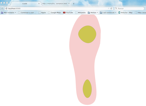
For Esole I write an interface using Javascript, a programming language of HTML and the Web, integrating with Raphael vector library to insert the svg and websocket, using the tutorial in the FabAcademy Archive (http://fabacademy.org/archives/2015/doc/WebSocketConsole.html) to communicate with the local server. I describe all parts of the working progress on my class page Github
The complete demo looks like the following:
Downloads
- eagle
- mill
- mill
- Press
- Press
- shoe+case model
- shoe+case printed
- sticker