 Francesca Mereu
mechanical design,machine design
This week we have to make a machine, including the end effector, build the passive parts and operate it manually. We have to document the group project and our individual contribution.
So It was finally Machine week! It is a group project and it should span two weeks The groups got assigned a prefabricated packages with motors, paper cut recipies, motor controlling boards and the Gestalt software package. Now it was time to make a machine. We had a good lecture and introduction into what lay ahead. But afterwards I found myself terribly lost, more than usual. So, the team is composed by four components: Giacomo Falaschi, David Montenegro, Troy Natchgall and me.
The idea is to make a machine that make wax rings. Giacomo has created a repository for the files in github: m2m ring
What we did: M2M, a machine that make wax rings
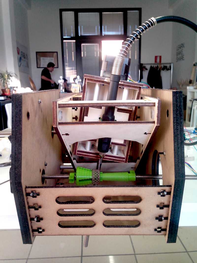
The project is to build a 4-axis milling machine for jewlery. CNC Milling machines can be divided into three categories, determined by the number of axes they have (i.e. the number of directions the spindle can move). A basic 3d mill has 3 axes: X, Y, and Z, or in more simple terms: it can move the spindle side to side, back to front, and up and down. Such a machine is suitable for engravings or bas-reliefs – pieces that are cut only from one side.
Intermediate mill has 4 axes: X, Y, Z and rotary A axis. This 4th axis can be used as a lathe (i.e. the spindle can move while the axis is rotating), as an automatic flipper (i.e. cut one side of an object, instruct 4th axis to move 180 degrees, cut the second side), or as an indexed cutter (i.e. cut one segment, rotate by a specified number of degrees, cut second segment, etc.).
For example, is possible to produce a ring with a pronged head by cutting from top and bottom and then repositioning the ring vertically to be finished off in a rotary fashion. Majority of traditional jewelry can be created this way.
CNC mill could produce wax models that cast easily and require little to no post-production work because of the high quality of the surface.
What I did:
My contribution is divided in two parts:
- design a mechanical piece: a spindle ring
- setting up electronics;
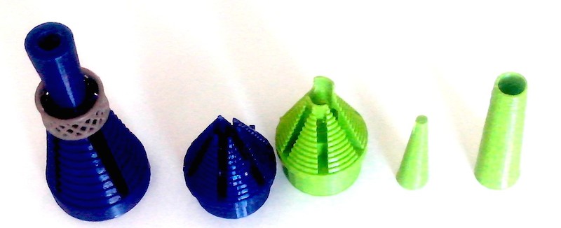
design a splindle wax rings
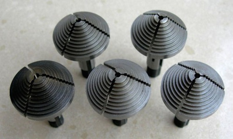
My work consists to design a spindle for the wax rings. I used Sketchup software for the first version and Rhinoceros for the second version. My reference for this design is a chuck for watch, like this:
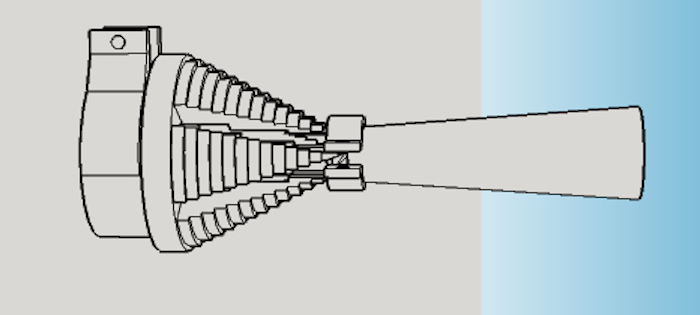
The spindle is composed by two parts:
-
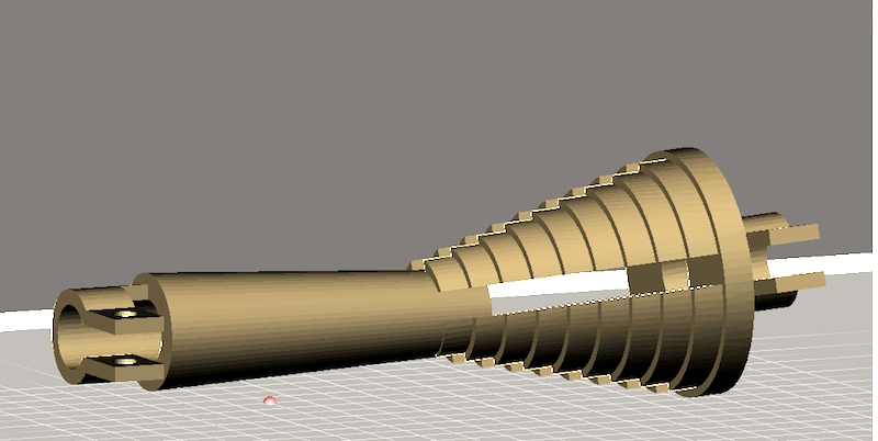
“spindle”-principal part. This piece is a conical structure
-
“plug slightly conical”.
It serves to insert it in the spindle so as to create a radial expansion thereof to ensure the locking of the ring on the step in which will be placed.
troubleshooting
The spindle has been corrected to the extent of 9.75 mm at the base of attack, also to make the clutch integral with the shaft of the machine. It has a clamp in which to insert the bolt.
In the other piece, the plug slightly conical, the diameter intended for coupling with the crankshaft has been reduced by 1,05 mm compared to the previous design, it has gone from 9.75 [mm] 8.55 [mm].
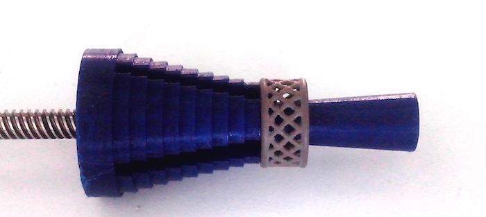
tips for improvement
I was prepared a clamp that will be mounted on the ends of the spindle, it will prevent that the plug can not slide with the vibrations.
In correspondence of the clamp base, I have introduced a gap perpendicular to the axis of revolution of the solid, this will allow greater flexibility in closure of the clamp itself.
The stop pin has a through hole of the diameter of the bar.
That’s a second version of the splindle, with a different conical plug too.
setting up Electronics:
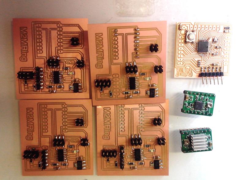
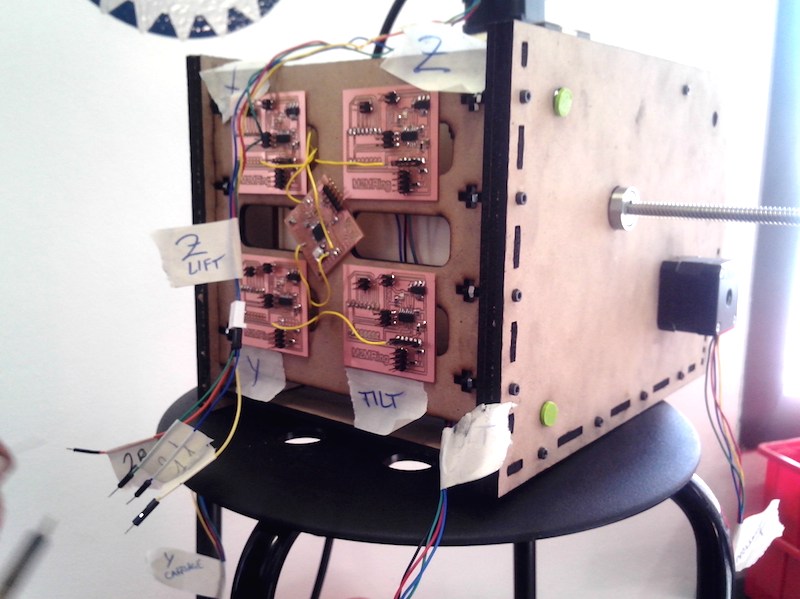
Also I’m setting up the electronics,for this, Troy designed some boards to control the stepper motors . I have fabricated with the milling machine Roland MDX 15 all boards. So, these are the boards:
board created/device used to do
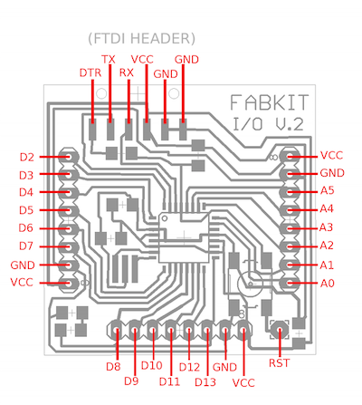
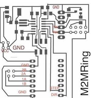
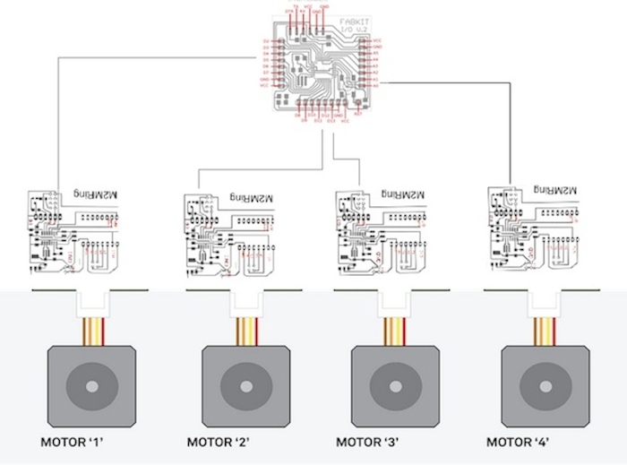
It does FabKit controller as the main gateway for communicating with the computer and four extension boards using ATTiny44 that control Pololu breakout drivers. All communication would happen via RS232 serial protocol. The standard defines the electrical characteristics and timing of signals, the meaning of signals, and the physical size and pinout of connectors.
We to want to stabilish a serial comunication with Fabkit and (4) M2M board
That are some pictures about this set up:
What I learned
I think that what I learnes is not only set up the electronics for the machine and I also designed some mechanical piece, solving some cinemtique problems. The most important thing that I learned in this assignment is not related to the machine, but related to group management. We were working together until the final day to the machine presentation. I think that is important that each member of the group have a role and a specific work: “One is part of all” as say Aristotle .
Sources
-splindle skp
-splindle stl
-conical plug skp
-conical plug stl
-clamp.stl
-conical plug2v.stl
-spindle 2 v.rds