 Francesca Mereu
Networking and communications
Goal
This week goal is to design and build a wired &/or wireless network connecting at least two processors
each board created/device used to do
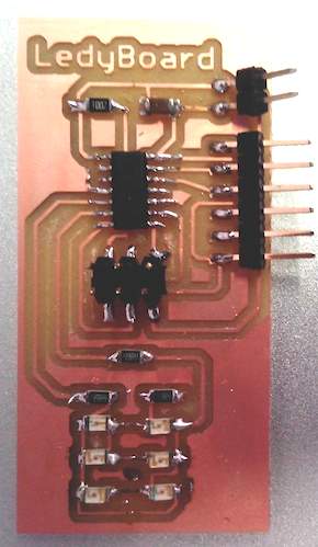
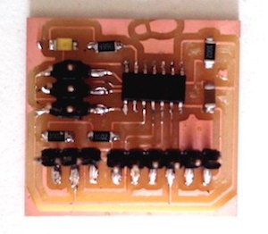
I was thinking to use two boards created by me: ledy board and press board. It could be a good experiment to make some advances to my final project. So it probably I could make a interaction about the insole and the led pendant.
These are the boards:
what protocol it uses and how it works to do
All communication would happen via RS232 serial protocol.
RS-232 is a standard for serial communication transmission of data. It formally defines the signals connecting between a DTE (data terminal equipment) such as a computer terminal, and a DCE (data circuit-terminating equipment, originally defined as data communication equipment), such as a modem. The RS-232 standard is commonly used in computer serial ports. The standard defines the electrical characteristics and timing of signals, the meaning of signals, and the physical size and pinout of connectors.
wired network
The network is a real time virtual control, so my computer (virtual control) is connected to the nodes and sends characters over the serial bus in real time. Every node of the network is listening to the serial line. If the correct character is received, the board executes an instruction.
The bridge board is connected to a computer via a FTDI cable. The two node boards are connected to the bridge board.
how the system works
The network is a real time virtual control, so my computer (virtual control) is connected to the nodes and sends characters over the serial bus in real time. Every node of the network is listening to the serial line. If the correct character is received, the board executes an instruction.
node 0. the bridge
The first node of the network is the bridge board. The bridge interfaces the computer with the rest of the nodes. You can add the FTDI connector to any of the nodes- I used the hello.bus.45.c code. I did a little modification to the software of these boards, in base to the Attiny44 datsheet.
That’s the modified code:
#define led_port PORTA
#define led_direction DDRA
#define led_pin (1 << PA7)

#define serial_port PORTB
#define serial_direction DDRB
#define serial_pins PINB
#define serial_pin_in (1 << PB0)
#define serial_pin_out (1 << PB1)

#define node_id '0'
node1
This board is listening and waiting to receive any of 2 specific characters. That’s the modified code:
#define led_port PORTA
#define led_direction DDRA
#define led_pin (1 << PA7)

#define serial_port PORTB
#define serial_direction DDRB
#define serial_pins PINB
#define serial_pin_in (1 << PB0)
#define serial_pin_out (1 << PB1)

#define node_id '1'
I need my bridge board to power my node boards and connect them to TX and RX. I plug my boards in as shown in the picture above.

Then I flashed the node board as node 1.
sudo make -f hello.bus.44.make program-usbtiny
the computer side
In the computer side the serial commands (characters) can be sent sent using the Arduino IDE serial monitor or a terminal emulator.
what I learned
Networking is like working in a team for the same results. A multiprocessing system is better than having a single powerful processor. I know this very well because I have coordinated teams at least six persons, and no matter when we were joint we always think that with our brains working together in parallel processing could make the double that only one brain. And it happens the same with Fablabs, it is not the machines, or the processes, the most powerful feature of a Fablab is the network of Fablabs.