 Francesca Mereu
output devices
Goal
The assignment for this week was to add a output device to a microcontroller board I have already designed, and program it to do something.
As my interests are about wearable electronics, I wanted to investigate something with it and to advance some of my project design.
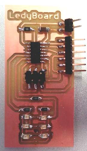
Ledy board: a wearable light board
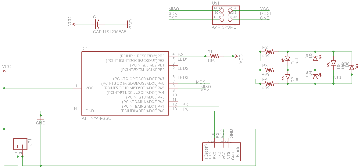
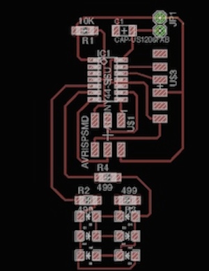
My goal was to create a small wearable board with the connection for the battery, using the ATtiny44 and exposing as many leds as possible. I started from the eagle schematic of the helloboard and this time, I decided to have a more traditional square board, but to add six leds.
Led array-Charlieplexing
Sketching the schematic I quickly found out that the avaiable pins, after adding the headers and button were only three. In order to support more LEDS I knew I could use a technique called CharliePlexing.
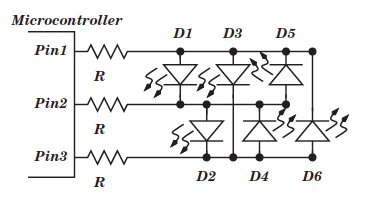
I used the technique of CharliePlexing to make a led array using few pins. This technique in few words allows to control up to n*(n-1) leds with n pins. When using more than 2 pins it does so by switching one of the pins as input rather than output, thus disconnecting the pin from the circuit. Thanks to this technique is possible to reduce duty cycle of the current that flows through the LEDs; thus, to maintain a given brightness, the peak current through the LEDs must be increased proportionately, which can quickly reach the maximum peak current limit of the LED. Nonetheless, Charlieplexing is a feasible technique for up to ten I/O lines, allowing up to 90 LEDs to be controlled. Controlling an equivalent number of LEDs using the standard multiplexing technique would require 19 I/O lines.
This image shows a microcontroller with just three I/O pins and six LEDs connected as shown.
Programming the board
I started by uploading the program that Neil made using FabIsp,hello.array.44.c. To upload the program to the microcontroller type this in the terminal:
sudo make program-usbtiny
That’s the Code:
#include <avr/io.h>
#include <util/delay.h>

#define output(directions,pin) (directions |= pin) // set port direction for output
#define input(directions,pin) (directions &= (~pin)) // set port direction for input
#define set(port,pin) (port |= pin) // set port pin
#define clear(port,pin) (port &= (~pin)) // clear port pin
#define pin_test(pins,pin) (pins & pin) // test for port pin
#define bit_test(byte,bit) (byte & (1 << bit)) // test for bit set

#define led_delay() _delay_ms(1) // LED delay

#define led_port PORTA
#define led_direction DDRA

#define led_port PORTB
#define led_direction DDRB

#define A (1 << PB2) // row 1
#define B (1 << PB0) // row 2
#define C (1 << PA7) // row 3

void flash(uint8_t from, uint8_t to, uint8_t delay) {
   //
   // source from, sink to, flash
   //
   static uint8_t i;
   set(led_port,from);
   clear(led_port,to);
   output(led_direction,from);
   output(led_direction,to);
   for (i = 0; i < delay; ++i)
       led_delay();
   input(led_direction,from);
   input(led_direction,to);
   }

void led_cycle(uint8_t number, uint8_t delay) {
   //
   // cycle through LEDs
   //
   uint8_t i;
   for (i = 0; i < number; ++i) {
      flash(B,A,delay);
      flash(C,A,delay);
	  flash(A,B,delay);
      flash(C,B,delay);
      flash(A,C,delay);
      flash(B,C,delay);
      }


   }


int main(void) {
   //
   // set clock divider to /1
   //
   CLKPR = (1 << CLKPCE);
   CLKPR = (0 << CLKPS3) | (0 << CLKPS2) | (0 << CLKPS1) | (0 << CLKPS0);
   //
   // main loop
   //
   while (1) {
      led_cycle(1,100);
      led_cycle(3,20);
      led_cycle(100,1);
      }
   }
What I learned
I am starting to feel that I can now achieve things that I could not do in the past. But I don’t know if this is because I learned something or I making something…However I’m learning every day something!