 Francesca Mereu
input devices
This week challenge is to create and program a board that measures something. I was intrigued by the step response sensors, as they are really general purpose and allow to measure a lot of different things.
For my final project I will also need to measure the flex of the foot, and this can be done using the step-response mechanism.
Flex sensor
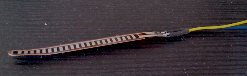
A simple flex sensor 2.2” in length. As the sensor is flexed, the resistance across the sensor increases. The resistance of the flex sensor changes when the metal pads are on the outside of the bend (text on inside of bend).
How it works
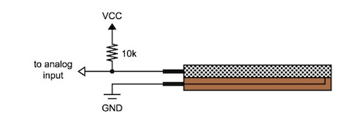
One side of the sensor is printed with a polymer ink that has conductive particles embedded in it. When the sensor is straight, the particles give the ink a resistance of about 30k Ohms. When the sensor is bent away from the ink, the conductive particles move further apart, increasing this resistance (to about 50k Ohms when the sensor is bent to 90º, as in the diagram below). When the sensor straightens out again, the resistance returns to the original value. By measuring the resistance, you can determine how much the sensor is being bent.

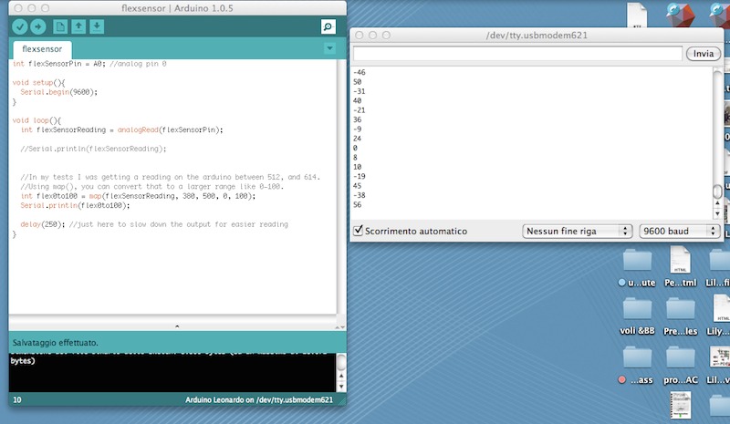
Testing the sensor with Arduino
I decided that I will just take the data from the flex sensor and bring it into the processing monitor, where I will visualize the data.
I used a sketch from [bildr blog ] (http://bildr.org/2012/11/flex-sensor-arduino/)
The Arduino code to be written was look very easy. There is a void setup where the port of the Serial Monitor is opened and a Void loop where the data is taken and resent as an analog data into Processing.
Here’s a basic Arduino sketch to show the output from your sensor:
void setup()
{
  // initialize serial communications
  Serial.begin(9600);
}

void loop()
{
  int sensor, degrees;

  // read the voltage from the voltage divider (sensor plus resistor)
  sensor = analogRead(0);

  // convert the voltage reading to inches
  // the first two numbers are the sensor values for straight (768) and bent (853)
  // the second two numbers are the degree readings we'll map that to (0 to 90 degrees)
  degrees = map(sensor, 768, 853, 0, 90);
  // note that the above numbers are ideal, your sensor's values will vary
  // to improve the accuracy, run the program, note your sensor's analog values
  // when it's straight and bent, and insert those values into the above function.

  // print out the result
  Serial.print("analog input: ");
  Serial.print(sensor,DEC);
  Serial.print("   degrees: ");
  Serial.println(degrees,DEC);

  // pause before taking the next reading
  delay(100);
}
Programming with Processing
As the program of the Processing was a little bit more difficult and it was the first time opening this software, it took me longer not just to write the code but to understand the process that Processing is doing through Arduino code.
-
In the first part, Processing tooks the data from Arduino opening the port:
import processing.serial.*; Serial myPort; // The serial port is opened -
In the second part, we set our CANVAS where the data is going to be visualized. All the code contained in a VOID SETUP is going to be fixed and will not vary all along the code:
void setup () { size(800, 800); // window size // List all the available serial ports println(Serial.list()); String portName = Serial.list()[0]; myPort = new Serial(this, portName, 9600); background(10,4,64); } -
In the thir part, we set the settings and parameters to visualize the data. In my case it will be a circle that varies its diameter in relation of the intensity of flex from the flexsensor. I remapped the data collected from Arduino into a maximum and minimum in order to fit always the circle in the size of my canvas. All the code contained in VOID DRAW and in VOID SERIALEVENT will be changing constantly:
 void draw () {
 }

 void serialEvent (Serial myPort) {
 int inByte = myPort.read();
 println(inByte);

 float yPos = height - inByte;

 float map = map(inByte,37,200,10,width-200);

 noFill();
 stroke(255);
 strokeWeight(5);
 ellipse(width/2,width/2,map,map);

 background(10,4,64);

 }
Board design: Flexino
The first step of the assignment was to decide what parts of the board would be necessary and how many of them were not. As i will need to save as much space as possible. I redesigned the whole board in order not not have an additional microcontroller neither its own programming pins, so the board reduces considerably its size and its price aswell.
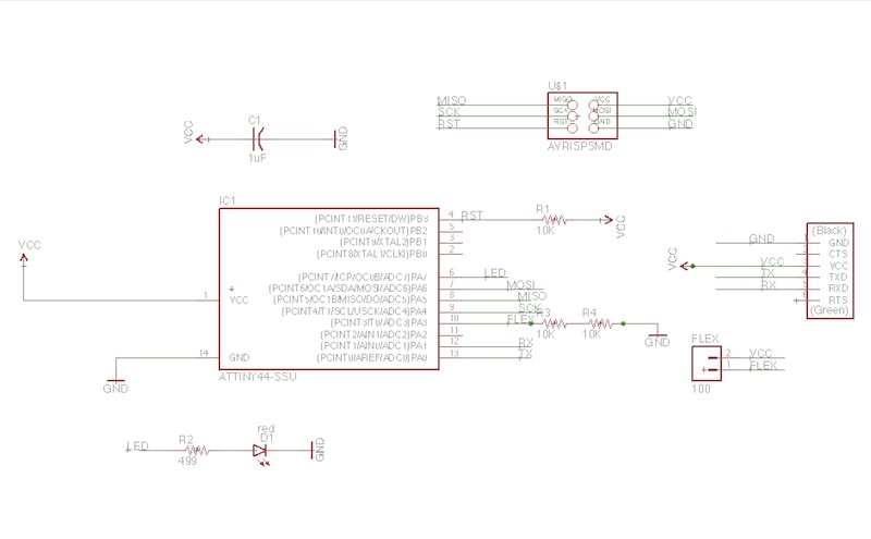
The board is redesigned with Eagle, incorporating just the necessary components:
- Attiny 44
- 3 resistors 10K
- 1 resistor 499
- 1 capacitor
- head pins conector (2)
- ftdi header
- head pin conector (6)


Programming the board
I programmed the board in C. This is the code.
#include <avr/io.h>
#include <util/delay.h>

#define output(directions,pin) (directions |= pin) // set port direction for output
#define set(port,pin) (port |= pin) // set port pin
#define clear(port,pin) (port &= (~pin)) // clear port pin
#define pin_test(pins,pin) (pins & pin) // test for port pin
#define bit_test(byte,bit) (byte & (1 << bit)) // test for bit set
#define bit_delay_time 102 // bit delay for 9600 with overhead
#define bit_delay() _delay_us(bit_delay_time) // RS232 bit delay
#define half_bit_delay() _delay_us(bit_delay_time/2) // RS232 half bit delay
#define char_delay() _delay_ms(10) // char delay

#define serial_port PORTA
#define serial_direction DDRA
#define serial_pin_out (1 << PA3)

void put_char(volatile unsigned char *port, unsigned char pin, char txchar) {

send character in txchar on port pin
   //    assumes line driver (inverts bits)


   clear(*port,pin);
   bit_delay();
   //
   // unrolled loop to write data bits
   //
   if bit_test(txchar,0)
      set(*port,pin);
   else
      clear(*port,pin);
   bit_delay();
   if bit_test(txchar,1)
      set(*port,pin);
   else
      clear(*port,pin);
   bit_delay();
   if bit_test(txchar,2)
      set(*port,pin);
   else
      clear(*port,pin);
   bit_delay();
   if bit_test(txchar,3)
      set(*port,pin);
   else
      clear(*port,pin);
   bit_delay();
   if bit_test(txchar,4)
      set(*port,pin);
   else
      clear(*port,pin);
   bit_delay();
   if bit_test(txchar,5)
      set(*port,pin);
   else
      clear(*port,pin);
   bit_delay();
   if bit_test(txchar,6)
      set(*port,pin);
   else
      clear(*port,pin);
   bit_delay();
   if bit_test(txchar,7)
      set(*port,pin);
   else
      clear(*port,pin);
   bit_delay();
   //
   // stop bit
   //
   set(*port,pin);
   bit_delay();
   //
   // char delay
   //
   bit_delay();
   }

 int main(void) {
//
// main
//
static char chr;
//
// set clock divider to /1
//
CLKPR = (1 << CLKPCE);
CLKPR = (0 << CLKPS3) | (0 << CLKPS2) | (0 << CLKPS1) | (0 << CLKPS0);
//
// initialize output pins
//
set(serial_port, serial_pin_out);
output(serial_direction, serial_pin_out);
//
// init A/D
//
ADMUX = (0 << REFS1) | (0 << REFS0) // Vcc ref
   | (0 << ADLAR) // right adjust
   |(0 << MUX5) | (0 << MUX4) | (0 << MUX3) | (0 << MUX2) | (1 << MUX1) | (1 << MUX0); // ADC3
ADCSRA = (1 << ADEN) // enable
   | (1 << ADPS2) | (1 << ADPS1) | (1 << ADPS0); // prescaler /128

   while (1) {
  //
  // send framing
  //
  put_char(&serial_port, serial_pin_out, 1);
  char_delay();
  put_char(&serial_port, serial_pin_out, 2);
  char_delay();
  put_char(&serial_port, serial_pin_out, 3);
  char_delay();
  put_char(&serial_port, serial_pin_out, 4);
  char_delay();
  //
  // initiate conversion
  //
  ADCSRA |= (1 << ADSC);
  //
  // wait for completion
  //
  while (ADCSRA & (1 << ADSC))
     ;
  //
  // send result
  //
  chr = ADCL;
  put_char(&serial_port, serial_pin_out, chr);
  char_delay();
  chr = ADCH;
  put_char(&serial_port, serial_pin_out, chr);
  char_delay();
  }
   }
Source Files
-eagle-brd
-eagle-sch
-flexino Board
-flexino Board
-flex code Arduino
-flex code Processing
-flex code
-flex code