 Francesca Mereu
electronics production
This week assigment is related to producing printed circuit boards. In particular we were asked to mill, stuff and program the Fab ISP board, which allows to program brand new AVR microcontrollers with the desired firmware.
FAB ISP
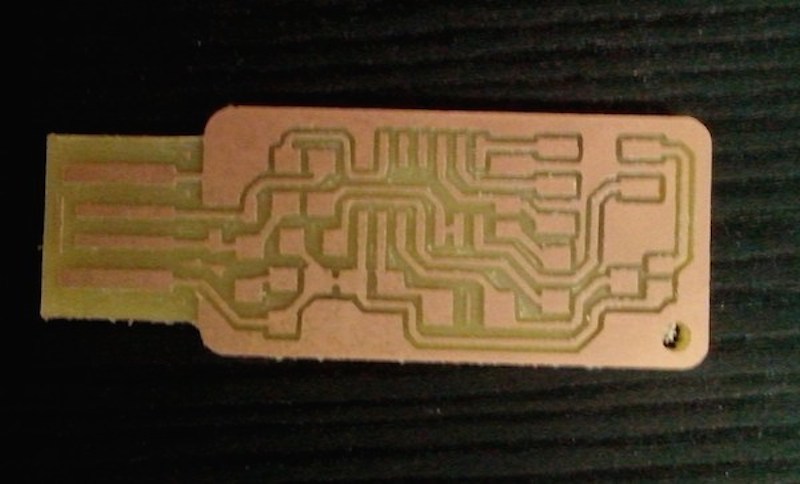
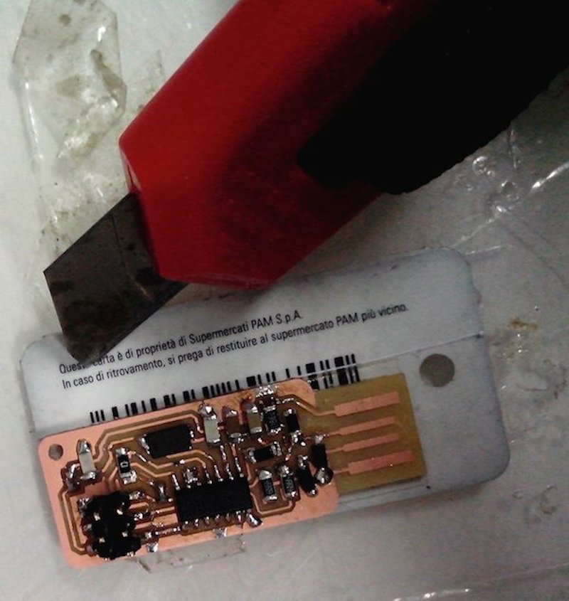
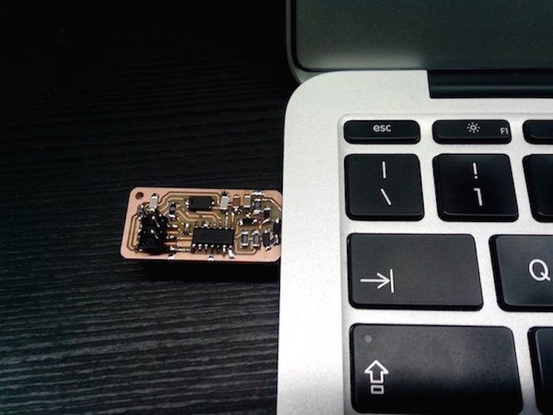
The FAB ISP design we decided to build in the lab is the Andy’s version. This board’s design is particularly interesting because it replaces the standard USB connector with traces milled on the board. The only required addition is some spacer added on the bottom of the board in order to have the required tickness for it to properly fit into a normal PC USB slot.
Milling the board
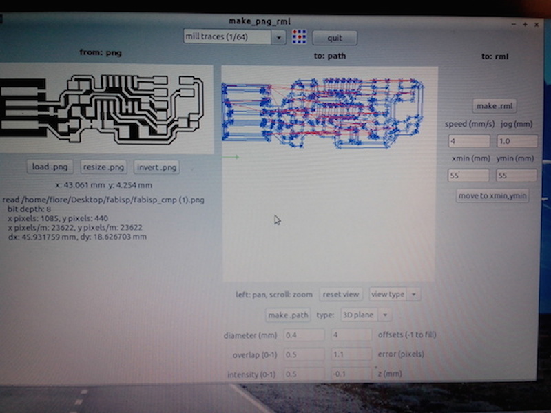
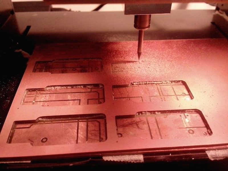
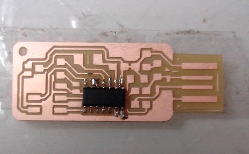
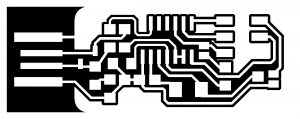
I milled the board starting from the PNG design available on the class webpage, using the Fab Modules on the lab’s Roland MDX-15 Modela mill present in the lab.
For milling the traces I used the 1/64’’ inch bit, while for cutting out the board from the FR-1 sheet I used the 1/32’’ inch bits. The first milling experiments where not very successful as traces on the upper right corner of the board were not milled properly.
Stuffing the FabISP
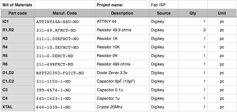
Before starting the actual stuffing I used a bill of materials of my instructor advice, matching codes in the schematic with a description and quantity required for each part. This helped me a lot in collecting components from the lab inventory, and will also be useful to track which components are needed to make another similar board in the future.

I also managed to salvage the ISP connector from an old board, so I had all material ready.
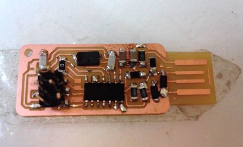
I had never soldered SMD components before, so found it quite intimidating handling such small parts. The process took me a couple of hours to complete, mostly because I couldn’t get some of the components to sit cleanly. Another lesson is I should use less solder possible before adding the components to get an easier alignment.
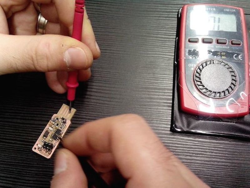
By testing all the connections to the ATTiny pins I could be more confident while progressing, but later I realized that some of the could be redone in a much cleaner way.
Programming the FabISP
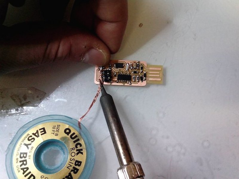
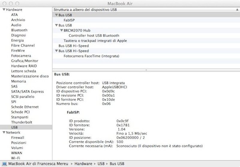
Being my first board I wasn’t really sure it would work at first. I downloaded the firmware plus all dependencies and followed the make clean, make program cycle using my instructor FabISP plugged on a second USB port. No error message, so I unsoldered the jumper but my board wouldn’t be recognized.
After several tries,restoring the jumper, the process this time was successful, my ISP was recognized by OSX, and it also worked for programming one of my collegues board.