Final Project (Interactive Goose Game)
PROJECT PRESENTATION - 24th of June 2015 (final presentation)

PROJECT UPDATE - 19th of June 2015 (programming)
Electronics, one of the stages of the development I'm most scared of. Since my electronic "background" is less than zero, if I'll encounter any unexpected error I won't be able to finish my project. Is that simple. All this pressure and "only" for a couple of well written code... would I be able to pull it off? I'll go step by step and let's see how I'm going to manage.
Firstly, I have sketched a logic tree and divided the expected program in to individual parts / stages. A big system divided into smaller, individual problems would be much easier to solve and to debug. The resulting logic tree can be seen in next image.

As we can see, using this logic tree, I can program everything individually and focusing only on the matter in hand. Easy to say, but let's go and apply this logic and we'll see what will come out.
The RANDOM stage only generates a random value between 0 and 1, 0 being the red player and 1 being the green player.
The INIT stage lights up the players LED, positions the carriage by searching the home position and finally positions the carriage beneath the first green square. At this point, the player should position the tokens on their places, the red token with the first red square and the green token with the first green square.
The WAIT_RED stage is taking turn when the red player should throw the dice. The program will wait a number from the PC (for checking/storing reason) and give instructions to the user.
The WAIT_PUSH stage will wait a push action from the player after he/she moved his token according with the random number it came up.
The WAIT_GREEN stage will take turn when the green player's turn and will wait a number from PC. This number will be checked for validity and stored for further use.
The MOVE stage will move the green players token according with the previously stored number.
The FINISH stage will give a visual feedback for the winner and ask if ready for a new game.
PROJECT UPDATE - 10th of June 2015 (implementation)
Since our presentation (FabLab León) got scheduled on to 24th of June I had more time to finish the final project and set everything up to a working stage. This week I got focused on 3D printing and wanned to implement everything together. I had designed and 3D printed every missing part (bushing, carriage, belt clamps, tokens, etc.). When I had everything ready and had all the kit prepared I have started the final mechanical stage of the project: implement everything together (mechanics with electronics) to a working stage. I needed smooth and easy movements on every direction and to make sure that the expected tolerance is the actual got tolerance (carriage and top acryl aren´t touching each other, nor generating any friction).
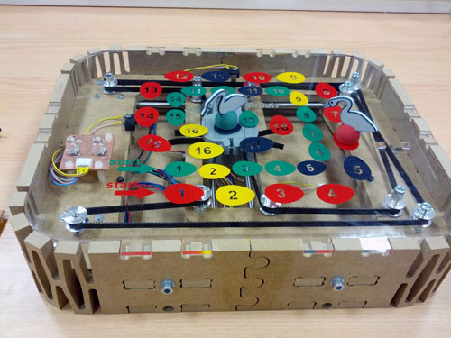
After this implementation everything turn out to be quite as expected and the result was / is really awesome (see image). From this point forward I only need to program the board and present it during the presentation class on the 24th.
None the less, I have noticed couple of small problems with the project. Since, the used magnets for moving the token weren't strong enough I have used three of them, but even so that wasn't generating enough magnetic field for not to lose the token during the movement. Sad, but for this first version I'll use light stepper movements and hope for the best.
The second problem I had was the tension of the timing belt. When the carriage was on the center of the game, the tension of the timing belt was normal and the steppers where generating nice movements. But when the carriage was reaching one of the sides, the belt was tensioning a lot and steps where skipped, kind of jamming the x/y movements. This variation of the tension can be the result of my error: 4 of the timing pulleys have 1 mm bigger holes than needed and the resulting tolerance is way too big. When I was drilling the holes in the DM support, I haven't checked the drill diameter and was resulting to be bigger than expected. Entirely my fault!
Another improvement can be the resistance of the shaft supporting acryl. I have used 4 mm thick acryl and made 6 of them (just in case) but while I was implementing everything they where keep broking. Finally, I broke every acryl support and had to improvise. I made it from DM and used screws to fix it. It had worked well.
PROJECT UPDATE - 29th of May 2015 (electronics)
This week I have started with the electronic schematics, which cost me quite some time, and building the PCB board afterwards. After the schematics design the board layup was quite straight forward, but unfortunately I haven’t managed to make the board without one bridge and a couple of patches. The milling process was quite smooth with some small incidents, but in the end the boards came out awesome! The small incident I had was because of some really close tracks and the 1/64 end mill didn’t milled between these tracks. I have overcome this issue by changing the end mill to a 0.01” and update the design to mill only the skipped tracks. In the end I had finished milling out both of the boards (main board and control board) and had to start soldering the boards.
The stuffing part was quite easy since I had all the components on hand, but it really took me some time to finish it, especially the microcontroller. The Atmega328 is a quite small component and had to pay special attention to solder all the pins correctly without short circuiting anything. When I finished soldering I really didn’t knew if the board was working or not, but it really looked amazing and I was/am really proud of the result.

Before starting programming the board I wanned to be sure that everything is working properly and started testing out every motor, LED, bumper and switch. Have written a small program for this testing to move motors, light up LED’s and give feedback of the pressed switches or bumpers. The LED’s where working properly from the start, but the bumpers and switches where giving me some errors. Sometimes they were working and sometimes they were not. Weird! Some research over the internet and I already knew where my problem was: when setting up the pins I was using the INPUT command instead of the INPUT_PULLUP command. Updating the code and the bumpers and switches started to work properly. I had another issue with the motors: they where stubborn and nothing seemed to move them. In the code I had everything set up correctly, but without any result. Went back to the board and with a tester and started to eliminate possible connection problems. And there it was: I had couple of pins poorly soldered. Reflow the solder on the motor drivers and the motors have started to move smoothly. At this point I had everything working separately and I only needed a nice program to finish my final project. And of course, I was still missing a couple of 3D printed parts.
#include "Stepper.h"
//#include "Hardware.h"
#define BUMPER1 4
#define BUMPER2 3
#define SWITCH1 6
#define SWITCH2 7
#define LED1 5
#define LED2 8
Stepper myStepper;
Stepper myStepper2;
void setup() {
pinMode(BUMPER1, INPUT_PULLUP);
pinMode(BUMPER2, INPUT_PULLUP);
pinMode(SWITCH1, INPUT_PULLUP);
pinMode(SWITCH2, INPUT_PULLUP);
pinMode(LED1, OUTPUT);
pinMode(LED2, OUTPUT);
myStepper.begin(A2, A3);
myStepper2.begin(A0, A1);
}
void loop() {
myStepper.move(HIGH, 10);
myStepper2.move(HIGH, 10);
delay(10);
if (digitalRead(BUMPER1) == LOW || digitalRead(SWITCH1) == LOW) {
//digitalWrite(LED2, LOW);
digitalWrite(LED2, HIGH);
} if (digitalRead(BUMPER2) == LOW || digitalRead(SWITCH2) == LOW) {
digitalWrite(LED1, HIGH);
//digitalWrite(LED1, LOW);
} else {
digitalWrite(LED2, LOW);
digitalWrite(LED1, LOW);
}
}
LED error
I have encountered one small error and I don't really know how to deal with it: both my feedback LEDs are lighting up nicely, but when I start moving the motors at the same time one of the LEDs fails to light up. Have checked for continuity, short circuits and voltage flows, but haven't find what can cause this issue. Can't have short circuit problems since the tracks (LEDs and motors) are in two separate parts of the board and I have this fail only when I'm moving the motors, otherwise both of my LEDs are working nicely. And in the end it came to me: delay. The delay was causing this fail and if I change the order of the LEDs the failure it changes to the other LED. Since this code is for checking errors I will let this as it is and will have to take in consideration using millis instead of delay's.
PROJECT UPDATE - 25th of May 2015 (digital fabrication)
I had finished updating my final design with the improved kinematics and started to materialize my project. Firstly I had used the CNC machine to cut out 10mm MDF for the actual box of the game.

I have cut out 2 pieces for the side of the game, in this design I had integrated flexures and joints, one piece for the bottom of the box and another middle piece to hold the electronics in place. Joining, mounting and fitting everything together was fairly easy and have used screws of different sizes to hold together the construction. The screws weren’t really necessary but I had fit them just in case.
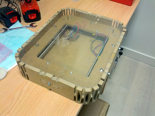
For the top piece of the box I have chosen acryl as the material which I had laser cut and engraved it. I have chosen this material because of his transparency and the view that can confer over the electronics and motor movements. Never less I have applied also a vinyl as for the game’s tracks, which came out quite nicely and the game is starting to look like a real children’s game.

PROJECT UPDATE - 18th of May 2015 (first presentation)

PROJECT UPDATE - 3d of April 2015 (re-design)
Taking in consideration Luciano's suggestion during one of the Regional Revisions I sat down and rethought my project's kinematics. Luciano was suggesting Ilan Moyer's solution for a lighter and more precise movements. I really liked the solution and I have tried to personalized it for my project. I took in consideration my bill of components and draw everything in 3D. I think everything will work quite nicely, but it will have to pass many trials and errors. I'm thinking to use a 10 mm MDF for the holding plate and will have to set up the desired tolerance correctly, I'm referring to the length of the plate and the actual movement of the carriage. In this 3D model, for a 30 cm long plate I only have 12 cm movement. Inacceptable! I will have to improve the movement length. Trial and error...


PROJECT UPDATE - 17th of March 2015 (components)
Have been busy lately, but I managed to detail all the important components needed for my project. Starting from stepper motors, belts, pulleys, bumpers, roods, acrylic and wood. I have already placed the orders in different places: sparkfun, BricoGeek and Farnell. Hopefully all the components will arrive shortly and I can spend much more time developing the essential steps.
PROJECT UPDATE - 10th of February 2015 (fisrt idea)
Firstly, I have tried to sketch out in 2D the essential mechanical parts of the project with all the details I could. I haven't took in consideration dimensions, I just waned to have an overlook on the mechanics. Basically, I have sketched out the axis movements with all the necessary details for a better understanding.
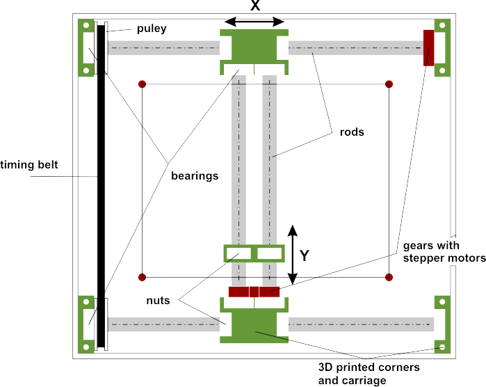
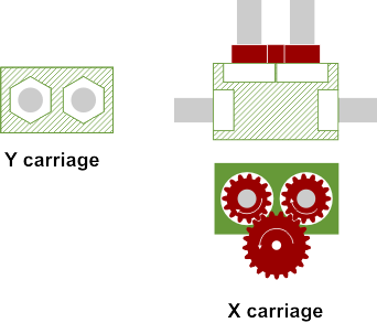
After the initial drawing I still had many mechanical details to define and therefore I have tried to draw separate drawings for each carriage, X and Y. In the next picture we can see the intended movements by each carriage. The Y carriage has two nuts embedded and by moving the rods the nuts will move in concordance. The details of the X carriage shows the actual movements of the Y carriage. One stepper motor starts spinning the bigger gear and the movement will translate to the two roods of the Y axis.
After I have figured it out the basic details necessary to model the project in 3D, I have started working in AutoCAD. At this point, it was necessary only to follow the steps, the details and to build the mechanics from bottom to top. I haven't paid much attention on dimensions, as I was mentioning earlier, but I really wouldn't like to oversize this interactive game.


PROJECT UPDATE - 3rd of February 2015 (project sketch)
Since I'm interested in the implementation of the new technologies in everyday objects, I started to play with different ideas of implementing the new technologies in something traditional. From these wild ideas it occurred to me one really special: Interactive Goose Game. Not the traditional Goose Game where two children are playing each other face-to-face, but the interactive one! The one you can play over the Internet! A traditional game which connects to the Internet, synchronizes with another game and the users can play each other over the Internet.
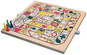
The project itself can be a really ambitious project, but in the end I think it will worth it. In the next steps I'll try to describe the technical characteristics it may require the mentioned interactive game.
From mechanical point of view we would have only X and Y movement, which can be controlled by two stepper motors. These motors will move the token, which is synchronized with the other game over the internet. The actual movement (since the token is not fixed to the board) it can be made with magnets. The principal magnet moves along the X and Y, and drags along with him the token from the board. It can be made, but will have to check interference issues if they are any.
From electronics point of view a microcontroller will be needed for the game itself, and another one for the dice. Other electronic parts may include: bumpers, stepper motors, communication controllers, accelerometer, LEDs, etc.
From programming point of view a microcontroller can control all the movements, all the data income and outcome would happen with the communication controllers. If the dice will be connected we can control the token's movement even locally.
From 3D fabrication point of view I will have to design and build a slim box, which would contain all the electronics, making sure that everything fits together perfectly and works smoothly.


