Weekly_Assignments :
- design and build a wired &/or wireless network connecting at least two processors
Useful links:
What I have used:
-
Eletronics Design : Eagle Freeware
-
Roland MDX-20
-
Soldering Station
-
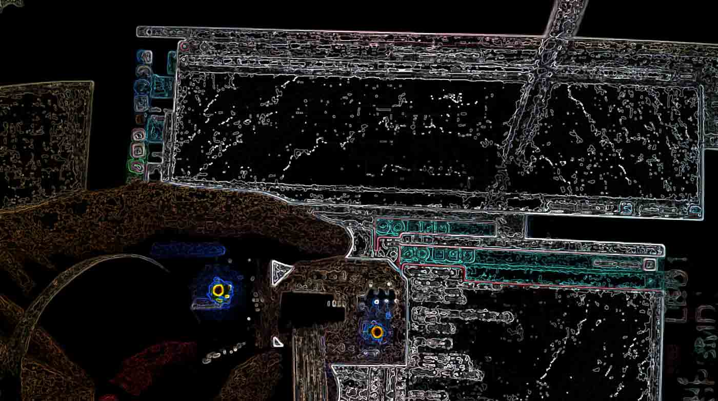
hello.bus.45.bridge.cad board traces interior
introduction
First of all, as suggested by many of the previous students of FabAcademy, I started by reading the tutorial from the guys from Providence: Networking - Hello Serial Bus - AS220 Then I downloaded the files needed to mill the bridge and node boards. It has been a lucky guess to check all the components I had before starting to mill the pcbs (all with attiny 45), since I only found one attiny 45 and many attiny 44. So I decided to create a node with attiny 44 e to reuse the original bridge with attiny 45 (whith any changes from the original).
NODE-44 (node creation with attiny44)
I brought the components on Eagle and I started to dedign the new board. The attiny 44 has much more available pins than the 45, so the idea is to build a board that can make the empty pins available, so that they can be connected to another board with sensors or other outputs through the available pins.
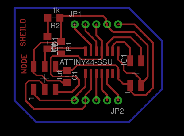
As you can see from the image, the green pins are used to connect the node 44 to anoother board, where they will host i.e. some sensors. It would be interesting to create a little protocol to read the value of the sensors, just directly calling the corresponding node.
For creating the files .png I used the usual workflow, by now working and proved.
eagle for circuit design —> export monocrome 1000 pixel - drill.png file, only the hole layer - trace.png file, circuit+hole layer - cut.png file, only the contour layer (bottom layer in this case)
photoshop to import aeverything in one single file, in the same position and export again the single file.
FabModules 1/64 for trace.png 1/32 for drill.png and cut.png

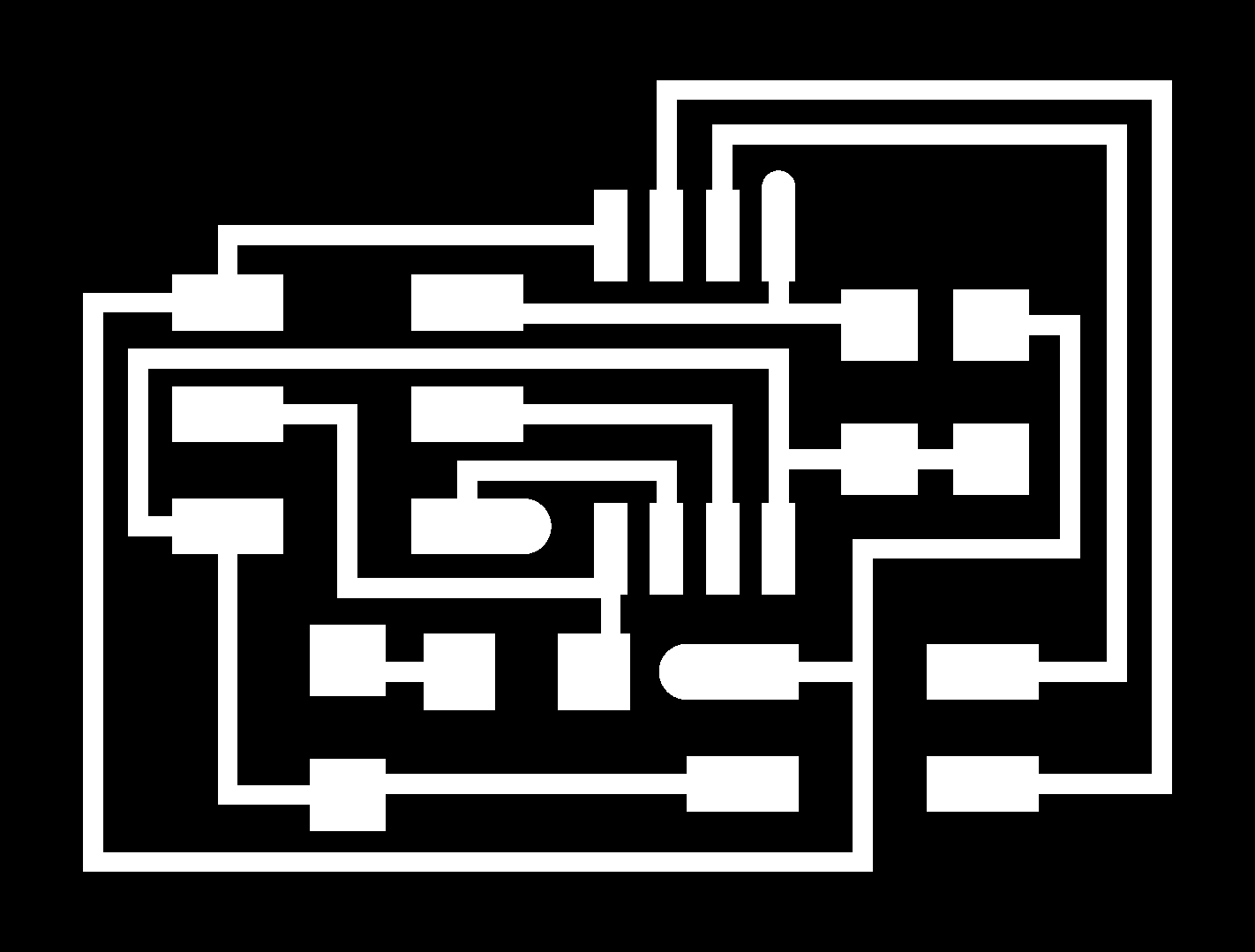
trace1.png

drill.png

cut.png
Programming!
Bridge attiny45
I only modified the code string regarding the name of the node on the hello.bus.45.c code:
#define node_id '0'
and I have than uploaded everything via fab isp and my Make (modified in order to upload on the attiny 45).
NODE-44
By changing the MCU I had to make more changes, but nothing too hard: I surprised myself indeed, by uploading everything at the first try, without making any mistakes with the code and the readdress of the pins.
I analyzed the code and modified the input, output and led pins. Of course, inserting node 1.
#define led_port PORTA
#define led_direction DDRA
#define led_pin (1 << PA6)

#define serial_port PORTB
#define serial_direction DDRB
#define serial_pins PINB
#define serial_pin_in (1 << PB0)
#define serial_pin_out (1 << PB1)

#define node_id '1'
Final output result
Conclusion
In this class I learnt the importance of the small microcontrollers such as the attiny 44 and attiny 45. I feel very lucky, since I got to see the network work right away, even though I had to create a board with another MCU! Actually, I am satisfied about this assignment, but not completely since I would have liked to create a shield too with some sensors for node 44, that could than be questioned (perhaps creating a specific protocol!) It is definetely something I will do, because creating a network like this has very small costs and make the whole project extremely scalable and modular. I already have in mind many projects that can feature a system like this…that’s great!
- in addition for my final project I have created a easy protocol for control servo motor and RGB led by using ESP8266