Weekly_Assignments :
- add an output device to a microcontroller board you've designed and program it to do something
Software
- Eletronics Design : Eagle Freeware
- FabModules
Useful links:
Materials - Machine
RGB 3.3v Servo 5v board
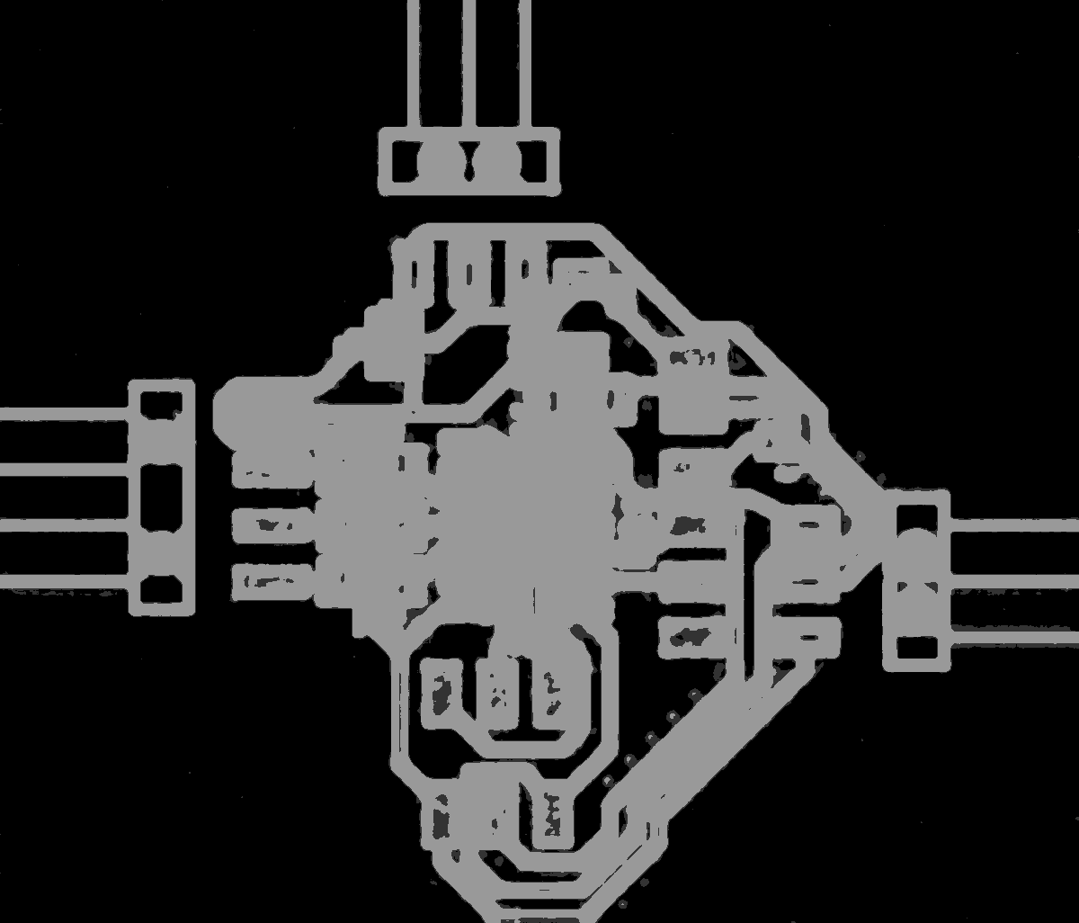
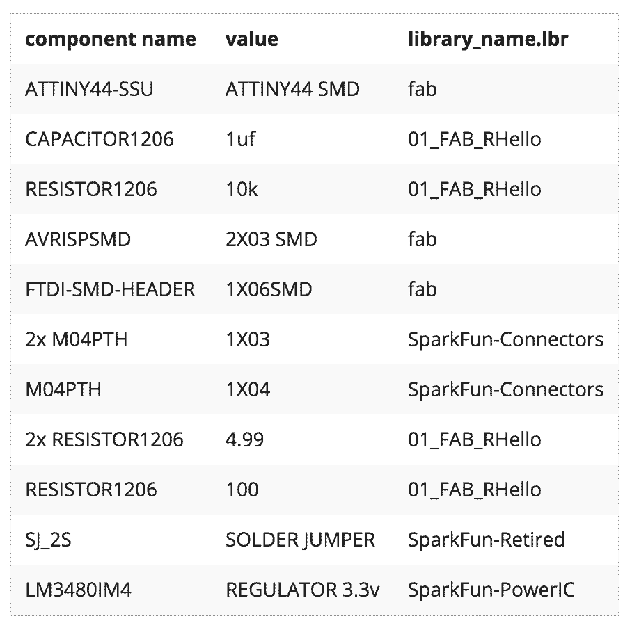
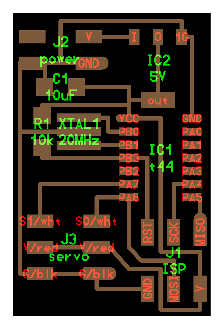
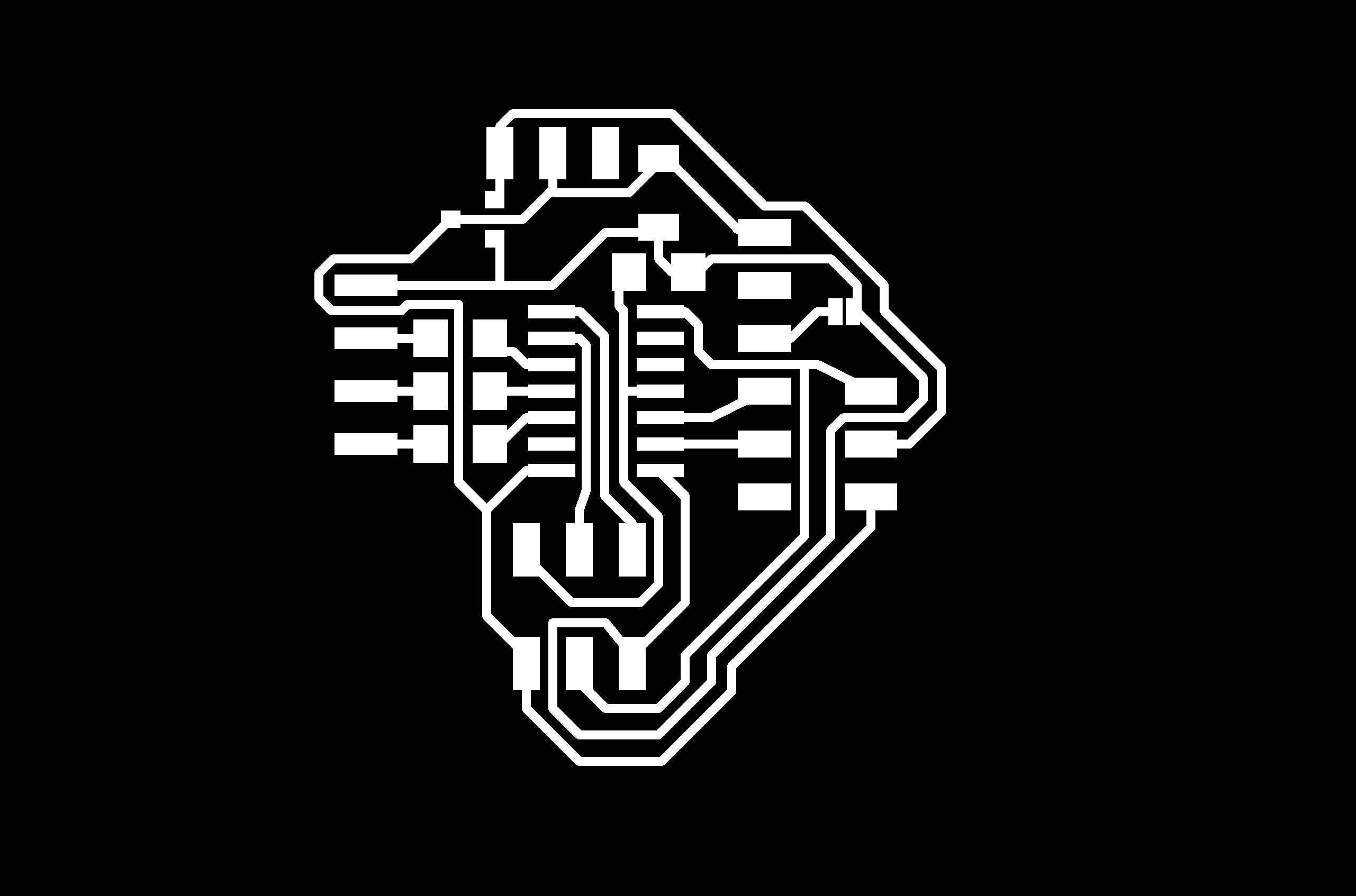
Eagle design
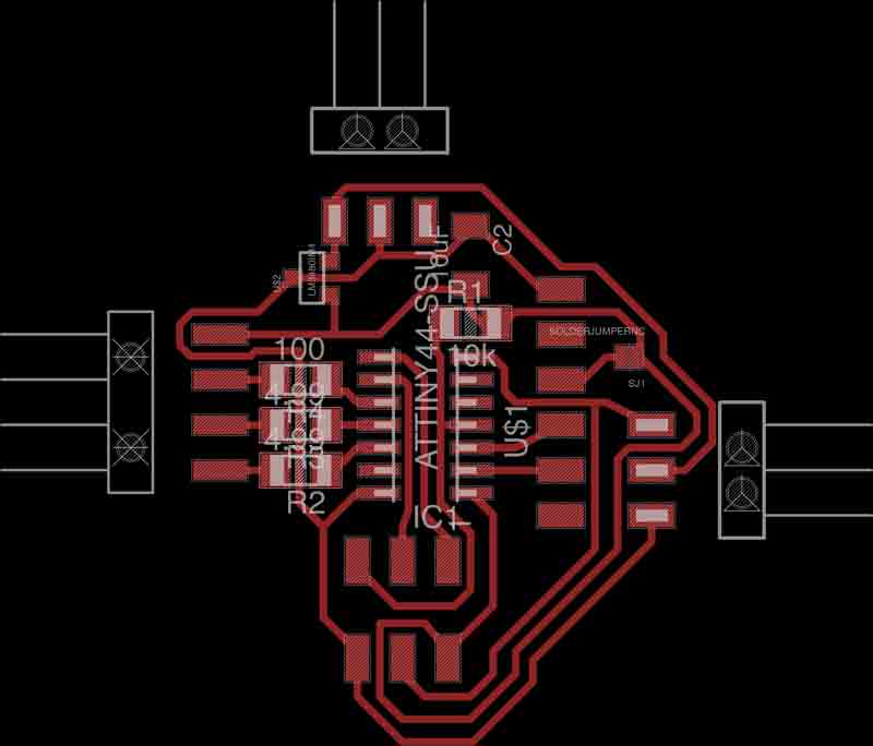
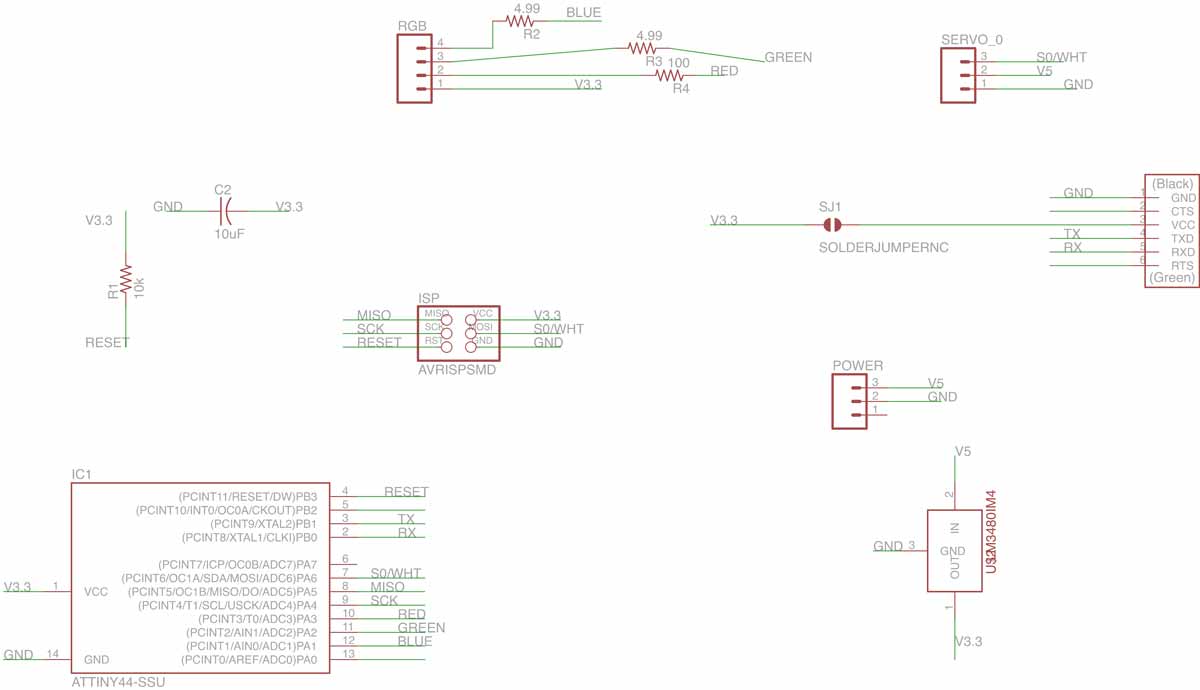
I started from servo neil’s board, I removed the resonator 20mhz and I added linear voltage regulator LM3480 for operate 2 different voltage:
- 5v for Servo (via hardware)
- 3.3v for rgb and future olimex MOD-WIFI-ESP8266-DEV
with this board and the olimex wifi maybe I will able to comand my twister cube, but for now I want test my output board directly by FTDI so Fiore suggest me to insert the FTDI predisposition.
I have also kept the external power pin, for use both board (olimex+SERVO5vRGB3.3v) with the same battery package.
UPDATE 03/16
**LM3480-3.3 after discuss with my local instructor is insufficent for transmit power at ESP8266. from datasheet
VIN =VNOM +1.5V 1mA≤IOUT ≤100mA
max Iout is 100mA !
in according to ESP8266 datasheet
in chapter 7 under “current consumption” the minimum consumption in Transmit 802.11n, MCS7, POUT=+14dBm is 135mA !!!!!!
After reading carefully the ESP8266 rev A olimex datasheet I discover that the Input high voltage is 3.6v so I decided to re-build my RGBservo board without regulator, for test with a 3.7v lipo battery.
Programming!
For test the RGB and servo CODE by neil and I modified for the attiny44 version instead attiny45(original) and I re-set the pin direction/number.
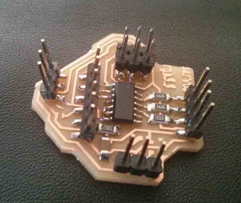
Final output result
Conclusion
Now I really want try to write the code that can control this board direct from the olimex esp8266! I tryed to find some tutorial to use esp8266, or write some similar code that listen the command direct from the FTDI for control servo and RGB in order to try to write something similar for use after the connection on esp8266… but for now the time is over.
For sure before the networking week, I must redisign the board with the hole in place of the pin connector, to improve the board and make it more compact!