****************************************************************************************************************
ASSIGNMENT: WRITE A DESKTOP APPLICATION THAT INTERFACES WITH AN INPUT AND OUTPUT DEVICE
PROJECT: DRAW WITH 2 POTENTIOMETERS
INPUT: POTENTIOMETER // PUSH BUTTON
SOFT: IDE ARDUINO 1.6.3 // PROCESSING
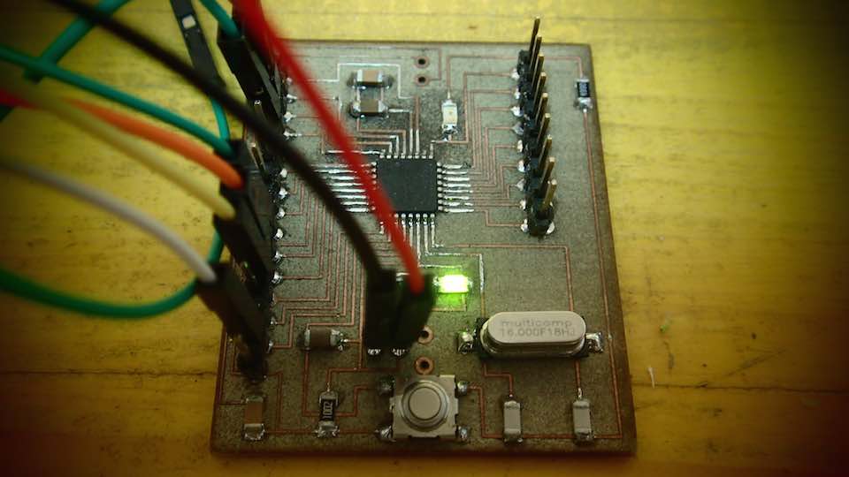
BOARD: SATSHAKIT BY --> DANIELE INGRASSIA // GIT HUB REPOSITORY OF THE PROJECT
LIBRARY: PROCESSING 2 - ARDUINO // ARDUINO FIRMATA
TUTORIAL: ARDUINO AND PROCESSING
DOWNLOAD:
****************************************************************************************************************
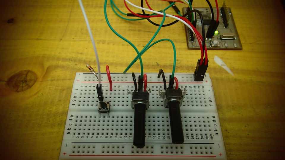
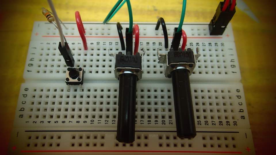
COMPONENT USED FOR THE EXERCISE : 2X POTENTIOMETERS - 1 PUSH BUTTON - 1 RESISTOR 10k
I followed the Arduino and Processing tutorial linked to the tutorial section on this page
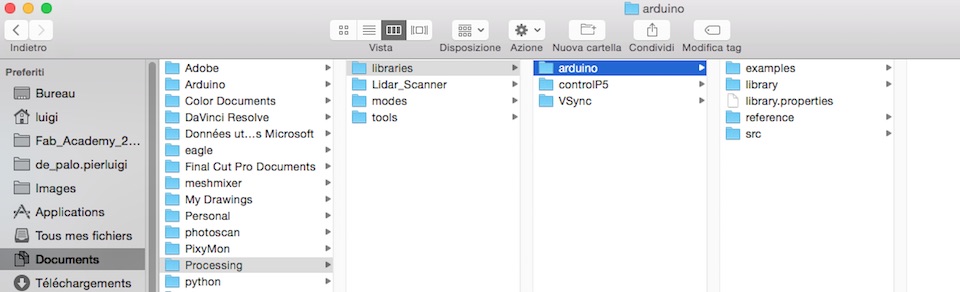
Download the PROCESSING 2 - ARDUINO library
Unzip the library and copy the "arduino" folder into the "libraries" sub-folder of my Processing Sketchbook.
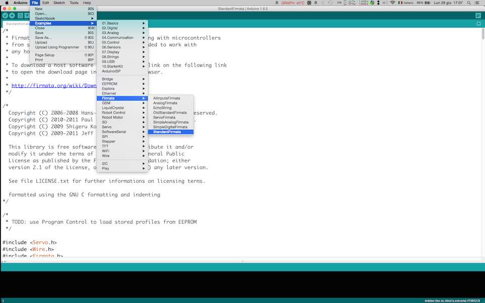
Run Arduino, open the Examples > Firmata > StandardFirmata sketch, and upload it to the Arduino board.
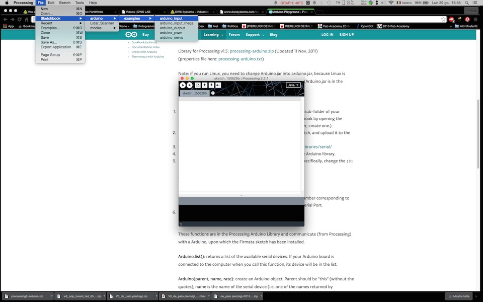
In Processing, open one of the examples that comes with the Arduino library.
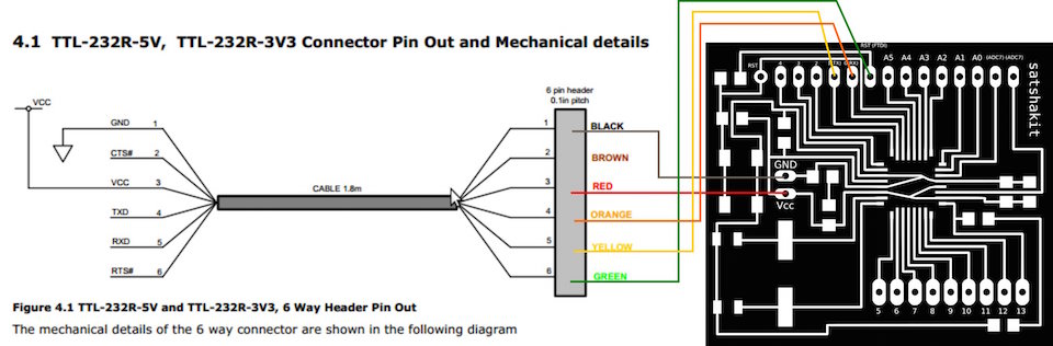
Connect the SATSHAKIT with a FTDI cable according to the image below
List of the changes made to the sketch :
Added a color variable called : color ballc
Change the size of the renderer
I added an "IF" statement that checks the status of the push button connected to pin number 4
Then delete the previous drawings and change the color of the ball.
I created an Ellipse function that moves according to the values collected from the microcontroller analog input
            /*

Modified Sketch By Pierluigi De Palo -Opendot Fab Lab Milano-
Fab Academy 2015 - INTERFACE AND APPLICATION PROGRAMMING -


arduino_input

Demonstrates the reading of digital and analog pins of an Arduino board
running the StandardFirmata firmware.

To use:
* Using the Arduino software, upload the StandardFirmata example (located
  in Examples > Firmata > StandardFirmata) to your Arduino board.
* Run this sketch and look at the list of serial ports printed in the
  message area below. Note the index of the port corresponding to your
  Arduino board (the numbering starts at 0).  (Unless your Arduino board
  happens to be at index 0 in the list, the sketch probably won't work.
  Stop it and proceed with the instructions.)
* Modify the "arduino = new Arduino(...)" line below, changing the number
  in Arduino.list()[0] to the number corresponding to the serial port of
  your Arduino board.  Alternatively, you can replace Arduino.list()[0]
  with the name of the serial port, in double quotes, e.g. "COM5" on Windows
  or "/dev/tty.usbmodem621" on Mac.
* Run this sketch. The squares show the values of the digital inputs (HIGH
  pins are filled, LOW pins are not). The circles show the values of the
  analog inputs (the bigger the circle, the higher the reading on the
  corresponding analog input pin). The pins are laid out as if the Arduino
  were held with the logo upright (i.e. pin 13 is at the upper left). Note
  that the readings from unconnected pins will fluctuate randomly.

For more information, see: http://playground.arduino.cc/Interfacing/Processing
*/

import processing.serial.*;

import cc.arduino.*;

Arduino arduino;

//color off = color(4, 79, 111);
//color on = color(84, 145, 158);
color ballc= color(255, 255, 255);  // set initial color of the ball to white

void setup() {
  size(600,400);

  // Prints out the available serial ports.
  println(Arduino.list());

  // Modify this line, by changing the "0" to the index of the serial
  // port corresponding to your Arduino board (as it appears in the list
  // printed by the line above).
  arduino = new Arduino(this, Arduino.list()[5], 57600);

  // Alternatively, use the name of the serial port corresponding to your
  // Arduino (in double-quotes), as in the following line.
  //arduino = new Arduino(this, "/dev/tty.usbmodem621", 57600);

  for (int i = 0; i <= 13; i++)
    arduino.pinMode(i, Arduino.INPUT);   // Set the Arduino digital pins as inputs.
}


void draw() {
  if (arduino.digitalRead(4) == arduino.HIGH) {  // read the value of the digital pin 4 and check if is HIGH
    background(205);  //create the background to erase the draw
    ballc = color(random(0, 255), random(0, 255), random(0, 255));  // create a new random color for the ball

  }
  //background(205);
    fill(ballc);  // set the color to the ball
    noStroke();  // delete the stroke
    // create a ball according to the value of the potentiometer
    ellipse(map(arduino.analogRead(0),0,1024,0, width), map(arduino.analogRead(1),0,1024,0, height), 10, 10);
}